EP0891235B1 - Feinschneidpresse mit ringzacken- und gegenhalterzylinder - Google Patents
Feinschneidpresse mit ringzacken- und gegenhalterzylinder Download PDFInfo
- Publication number
- EP0891235B1 EP0891235B1 EP97907241A EP97907241A EP0891235B1 EP 0891235 B1 EP0891235 B1 EP 0891235B1 EP 97907241 A EP97907241 A EP 97907241A EP 97907241 A EP97907241 A EP 97907241A EP 0891235 B1 EP0891235 B1 EP 0891235B1
- Authority
- EP
- European Patent Office
- Prior art keywords
- cylinder
- ram
- working
- piston
- cylinders
- Prior art date
- Legal status (The legal status is an assumption and is not a legal conclusion. Google has not performed a legal analysis and makes no representation as to the accuracy of the status listed.)
- Expired - Lifetime
Links
Images


Classifications
-
- B—PERFORMING OPERATIONS; TRANSPORTING
- B30—PRESSES
- B30B—PRESSES IN GENERAL
- B30B1/00—Presses, using a press ram, characterised by the features of the drive therefor, pressure being transmitted directly, or through simple thrust or tension members only, to the press ram or platen
- B30B1/32—Presses, using a press ram, characterised by the features of the drive therefor, pressure being transmitted directly, or through simple thrust or tension members only, to the press ram or platen by plungers under fluid pressure
- B30B1/34—Presses, using a press ram, characterised by the features of the drive therefor, pressure being transmitted directly, or through simple thrust or tension members only, to the press ram or platen by plungers under fluid pressure involving a plurality of plungers acting on the platen
-
- B—PERFORMING OPERATIONS; TRANSPORTING
- B21—MECHANICAL METAL-WORKING WITHOUT ESSENTIALLY REMOVING MATERIAL; PUNCHING METAL
- B21D—WORKING OR PROCESSING OF SHEET METAL OR METAL TUBES, RODS OR PROFILES WITHOUT ESSENTIALLY REMOVING MATERIAL; PUNCHING METAL
- B21D28/00—Shaping by press-cutting; Perforating
- B21D28/02—Punching blanks or articles with or without obtaining scrap; Notching
- B21D28/16—Shoulder or burr prevention, e.g. fine-blanking
-
- B—PERFORMING OPERATIONS; TRANSPORTING
- B30—PRESSES
- B30B—PRESSES IN GENERAL
- B30B1/00—Presses, using a press ram, characterised by the features of the drive therefor, pressure being transmitted directly, or through simple thrust or tension members only, to the press ram or platen
- B30B1/26—Presses, using a press ram, characterised by the features of the drive therefor, pressure being transmitted directly, or through simple thrust or tension members only, to the press ram or platen by cams, eccentrics, or cranks
-
- B—PERFORMING OPERATIONS; TRANSPORTING
- B30—PRESSES
- B30B—PRESSES IN GENERAL
- B30B1/00—Presses, using a press ram, characterised by the features of the drive therefor, pressure being transmitted directly, or through simple thrust or tension members only, to the press ram or platen
- B30B1/32—Presses, using a press ram, characterised by the features of the drive therefor, pressure being transmitted directly, or through simple thrust or tension members only, to the press ram or platen by plungers under fluid pressure
- B30B1/323—Presses, using a press ram, characterised by the features of the drive therefor, pressure being transmitted directly, or through simple thrust or tension members only, to the press ram or platen by plungers under fluid pressure using low pressure long stroke opening and closing means, and high pressure short stroke cylinder means
-
- B—PERFORMING OPERATIONS; TRANSPORTING
- B30—PRESSES
- B30B—PRESSES IN GENERAL
- B30B15/00—Details of, or accessories for, presses; Auxiliary measures in connection with pressing
- B30B15/0029—Details of, or accessories for, presses; Auxiliary measures in connection with pressing means for adjusting the space between the press slide and the press table, i.e. the shut height
- B30B15/0035—Details of, or accessories for, presses; Auxiliary measures in connection with pressing means for adjusting the space between the press slide and the press table, i.e. the shut height using an adjustable connection between the press drive means and the press slide
-
- B—PERFORMING OPERATIONS; TRANSPORTING
- B30—PRESSES
- B30B—PRESSES IN GENERAL
- B30B15/00—Details of, or accessories for, presses; Auxiliary measures in connection with pressing
- B30B15/04—Frames; Guides
- B30B15/045—Mountings of press columns
-
- Y—GENERAL TAGGING OF NEW TECHNOLOGICAL DEVELOPMENTS; GENERAL TAGGING OF CROSS-SECTIONAL TECHNOLOGIES SPANNING OVER SEVERAL SECTIONS OF THE IPC; TECHNICAL SUBJECTS COVERED BY FORMER USPC CROSS-REFERENCE ART COLLECTIONS [XRACs] AND DIGESTS
- Y10—TECHNICAL SUBJECTS COVERED BY FORMER USPC
- Y10T—TECHNICAL SUBJECTS COVERED BY FORMER US CLASSIFICATION
- Y10T83/00—Cutting
- Y10T83/202—With product handling means
- Y10T83/2092—Means to move, guide, or permit free fall or flight of product
- Y10T83/2096—Means to move product out of contact with tool
- Y10T83/2135—Moving stripper timed with tool stroke
- Y10T83/215—Carried by moving tool element or its support
- Y10T83/2153—Fluid pressure actuated stripper
-
- Y—GENERAL TAGGING OF NEW TECHNOLOGICAL DEVELOPMENTS; GENERAL TAGGING OF CROSS-SECTIONAL TECHNOLOGIES SPANNING OVER SEVERAL SECTIONS OF THE IPC; TECHNICAL SUBJECTS COVERED BY FORMER USPC CROSS-REFERENCE ART COLLECTIONS [XRACs] AND DIGESTS
- Y10—TECHNICAL SUBJECTS COVERED BY FORMER USPC
- Y10T—TECHNICAL SUBJECTS COVERED BY FORMER US CLASSIFICATION
- Y10T83/00—Cutting
- Y10T83/869—Means to drive or to guide tool
- Y10T83/8821—With simple rectilinear reciprocating motion only
- Y10T83/8858—Fluid pressure actuated
-
- Y—GENERAL TAGGING OF NEW TECHNOLOGICAL DEVELOPMENTS; GENERAL TAGGING OF CROSS-SECTIONAL TECHNOLOGIES SPANNING OVER SEVERAL SECTIONS OF THE IPC; TECHNICAL SUBJECTS COVERED BY FORMER USPC CROSS-REFERENCE ART COLLECTIONS [XRACs] AND DIGESTS
- Y10—TECHNICAL SUBJECTS COVERED BY FORMER USPC
- Y10T—TECHNICAL SUBJECTS COVERED BY FORMER US CLASSIFICATION
- Y10T83/00—Cutting
- Y10T83/929—Tool or tool with support
- Y10T83/9411—Cutting couple type
- Y10T83/9423—Punching tool
Definitions
- the invention relates to a hydraulically or mechanically driven Fineblanking press with ring serrated and counter holder cylinder according to the preamble of claim 1.
- An essential feature of fineblanking is the embossing of a ring spike parallel to the cutting line on the lead frame side, to ensure that the material continues to flow to avoid; the ring spike is impressed through the ring-toothed cylinder.
- the workpiece is in the fineblanking process through a special sheet metal counterholder - in called another "counterholder" - from below against the upper tool pressed.
- the force of the Ring-toothed cylinder in the upper crosshead of the machine stand is arranged against the cutting force.
- the Counterholder cylinder in the plunger or in the working piston is integrated, presses the workpiece against the upper part of the tool; the counterholder support force acts on the cutting force opposite.
- the counter force of the ring-toothed cylinder is up to 50% and that of the counterpart up to 25% of the Worker.
- the ring-toothed cylinder is above the upper crosshead integrated in a traverse and with the Tappet firmly connected so that it is in sync with the Ram moved up.
- the counter holder cylinder is between Tappet and lower crosshead of the stand arranged.
- the piston of the serrated cylinder is replaced by a pressure-actuated support cylinder in its lower position kept and thereby remains in constant contact with the push pin of the upper tool.
- the pressure-actuated support cylinder pushes working strokes the ring-toothed piston in its lower basic position and at the same time strips off the ring-tooth punched grid.
- the piston of the counter-holding cylinder is actuated by a pressure medium Support cylinder in its upper position kept, which keeps him in constant contact with the pressure bolts of the lower tool remains.
- a pressure medium Support cylinder in its upper position kept, which keeps him in constant contact with the pressure bolts of the lower tool remains.
- a fineblanking press is now available Available, whose energy losses are greatly reduced. This is particularly due to the arrangement of the ring spikes and Counterholder cylinder reached during the working stroke of the ram clamp the lead frame or the fine blank without executing a stroke. It arises during the Working strokes between ring-toothed cylinder and ram none Relative movement; the ring-toothed cylinder support forces are taken up by the pestle. The main drive operator is not reduced by the ring-toothed cylinder pressure. At the same time, between arises during the working stroke Counterholder cylinder and stand no relative movement; the Counterholder cylinder support forces are absorbed by the stand. The main drive is driven by the Counterholder cylinder contact pressure not reduced.
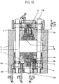
- a solution is shown in which the columns 3 are firmly connected to the plunger 1 .
- the columns 3 penetrate the stand 4 in the region of the upper crosshead and are firmly connected to the cross member 2 here.
- a double-acting ring serrated cylinder C is integrated in the traverse 2 .
- Below the plunger 1 the columns 3 are provided with a shoulder, which is designed as a piston 3.1 of the working cylinder A.
- the working cylinder A consists of the cylinder housing 5, which is integrated in the stator 4 , and piston 3.1, they form the pressure-actuated cylinder chamber 5.1.
- a cylinder piston unit B is arranged between the plunger 1 and the upper crosshead of the stand 4 ; the hydraulic effective area of the piston 7 is the same size as the piston area 3.1 .
- the counter-holding cylinder D is integrated below the plunger 1 in the lower crosshead of the stand 4 .
- the fineblanking press is shown here in the lower starting position.
- the plunger 1 is moved upwards by the rapid stroke cylinder G.
- the piston 7 displaces the pressure medium from the cylinder space 6.1 of the cylinder B , the pressure medium is shifted into the cylinder space 5.1 of the cylinder A via line 27.1, valve 26 and line 27 .
- the piston 35 of the counter-holding cylinder D is connected to the plunger 1 by the piston 44 of the pressure medium-loaded cylinder F ; it remains in constant contact with the pressure pin 36 and moves upwards with the feed movement of the ram 1 .
- the piston 44 is fixedly connected to the plunger 1 via connecting elements 46 . Due to the upward movement of the piston 33 , the pressure medium is shifted from the cylinder space 39 via line 37, valve 38 and line 37.1 into the cylinder space 34 .
- the contact force of the ring-toothed cylinder C also takes effect immediately after the valve 16 has been switched over, since the cylinder chamber 12 remains connected to the pressure medium source 18 and the cylinder chamber 15 is connected to the tank 17 via the valve 16 .
- the contact pressure is transferred via the pressure bolts 9 into the fineblanking tool for pressing in the ring-shaped contour.
- the ring-toothed cylinder support force is passed from the housing 8 into the cross member 2 and from here via the columns 3 into the plunger 1 .
- the work force of the main drive is not reduced by the ring serration pressure.
- the piston 21 of the cylinder E is relieved of pressure at the beginning of the working stroke via the valve 22 switch position "1", the piston 13 can be displaced upwards.
- the contact pressure of the counter-holding cylinder D also takes effect immediately after the valve 38 has been switched over, since the cylinder space 34 remains connected to the pressure medium source 40 and the cylinder space 39 is connected to the tank 41 via the valve 38 .
- the contact pressure is transmitted via the pressure bolts 36 into the fineblanking tool for pressing on the workpiece.
- the counter-holding cylinder support force is transmitted from the housing 30 into the stand 4 . During the working stroke, there is no relative movement between the counter-holding cylinder D and the workpiece in the tool.
- the piston 44 of the cylinder F is relieved of pressure at the beginning of the working stroke via valve 43 switch position "1"; the piston 35 moves relative to the working stroke of the plunger 1 downwards.
- the work force of the main drive is not reduced by the counter-pressure.
- valves 26, 16, 38, 22 and 43 are switched from switch position "1" to switch position "0".
- the cylinder space 6.1 of the cylinder B is connected to the pressure medium source 40 via the valve 26 and generates a counterforce to the pressure medium-actuated cylinder A , the work force is canceled.
- the cylinder chamber 15 of the ring prong cylinder C is connected to the pressure medium source 18 via the valve 16 and generates a counterforce to the cylinder chamber 12, the ring prong force is released.
- the support cylinder E is pressurized by switching valve 22 and pushes the piston 13 into its lower starting position; the lead frame is ejected via the pressure bolts 9 .
- the cylinder chamber 39 of the counter-holder cylinder D is connected to the pressure medium source 40 via the valve 38 and generates a counterforce to the cylinder chamber 34; the counter-holding force is released.
- the support cylinder F is pressurized by switching valve 43 and pushes the piston 35 into its upper starting position, in this case the fine stamped part is ejected via the pressure pin 36 .
- the ram 1 is moved downwards into the basic position of the machine by the quick-stroke cylinder G , the fineblanking cycle is ended.
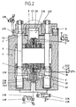
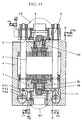
- the fineblanking press with single-acting cylinder systems is shown here.
- the arrangement of the ring-toothed cylinder C2 in the crossmember 2 and the counter-holding cylinder D2 between the plunger 1 and the stand 4 corresponds to FIG. 1.
- the fineblanking press is shown in the starting position.
- the ram 1 is moved upwards by the rapid stroke cylinder G.
- pressure medium is sucked into the main, ring spike and counter-holding cylinders via the suction valves 2.28, 2.15 and 2.39 .
- valves 2.16, 2.26, 2.38 are switched from switch position "0" to "1". Cylinder rooms 2.51, 2.12 and 2.33 are pressurized.
- the working cylinder A2 generates the punching force and moves the ram upwards.
- the piston 2.13 of the ring prong cylinder C2 presses the ring prong contour into the lead frame via the pressure bolts 9 .
- the ring-toothed cylinder support force is passed from the housing 2.8 into the cross member 2 and from here via the columns 3 into the plunger 1 .
- the work force of the main drive is not reduced by the ring spike pressure.
- the cylinder space 2.33 of the counter-holding cylinder D2 is pressurized at the start of the working stroke.
- the cylinder housing 2.30 which is connected to the pressure pin 2.36 and the plunger 1 via the support cylinder F , transmits the contact pressure to the workpiece via the pressure pin 2.36 .
- the counterholder support force is transmitted into the stand 4 via the piston 2.31 . There is no relative movement between the counter-cylinder D2 and the workpiece during the working stroke. The counter cylinder support force does not reduce the work force of the master cylinder.
- valves 2.16.2.22.2.39 and 2.43 are switched from switch position "1" to “0” and valve 2.26 from switch position "1" to “2".
- the cylinders A2, C2 and D2 are depressurized, the support cylinders E and F are pressurized.
- the support cylinder E pushes out the lead frame and the support cylinder F out the workpiece, as described in FIG. 1.
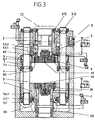
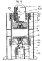
- FIGS. 1 and 2 A fine blanking press in a similar design to that described in FIGS. 1 and 2 is shown.
- the working cylinder A3 is arranged in the upper crosshead of the stand 4 .
- the area of the piston 3.5.2 is approximately the same size as the four areas of the piston 7 .
- the cylinder spaces 6.1 and 3.5.1 are pressurized.
- the force of the cylinder A3 is the same as the forces of the four cylinders B3.
- the ring- toothed cylinder C3 is integrated in the piston 3.5.2 of the working cylinder A3 .
- the active surfaces 3.12 and 3.15 correspond to the surfaces 12 and 15 according to FIG. 1.
- the course of the working cycle can be seen from the description according to FIG. 1.
- the fineblanking press is provided with an installation space adjustment 3.6 , which is arranged below the ram 1 .
- the columns 3 are provided with a thread 3.6.1 at the lower end.
- the threaded nut 3.7 is rotatably fastened to the plunger 1 with fastening elements 3.7.1 .
- the threaded nuts 3.7 are provided with teeth for chain or toothed belt drives.
- the four nuts 3.7 are adjusted synchronously via a chain or a toothed belt. The adjustment can be made so that at different heights of the fineblanking tools, the stop surface 7.1 of the piston 7 hits the cylinder housing 6 at the end of the working stroke.
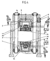
- the example here shows a fineblanking press with simple acting cylinder systems.
- the way it works and works is similar to that described in Fig. 2, the cylinder arrangement is similar to that shown in Fig. 3.
- FIGS. 1 and 3 Shown is a fineblanking press, the mode of operation of which was described in FIGS. 1 and 3.
- the four bias cylinders B and B3 (Fig. 1, 3) are replaced by a cylinder B5 .
- the cylinder B5 is arranged between the stand 4 and a second crossbeam 5.2 .
- An installation space adjustment 3.6 as described in FIG. 3, is arranged below the cross member 5.2 .
- This version of the fineblanking press differs from the version according to FIG. 1 in that the four working cylinders A are replaced by a cylinder A6 with installation space adjustment.
- the counter-holding cylinder D6 is integrated in the piston 6.6 of the working cylinder A6 .
- the mode of operation is described in Fig. 2 for the main drive and in Fig. 1 for the ring prong and counter-holding cylinder.
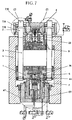
- the structure of the fineblanking press shown here is identical to that of FIG. 6, only the ring-serrated cylinder C6 is replaced by four cylinders C7, which are arranged in the upper region of the columns 3 .
- the mode of operation of the ring-toothed cylinders is described in FIG. 1.
- the working and serrated cylinders are arranged on the columns 3 of the fineblanking press; an installation space adjustment, as shown in Fig. 3, can alternatively be installed.
- the ring-toothed cylinders C9 are designed as shown in FIG. 7, and the working cylinders A9 correspond to the version according to FIGS. 1 and 2. For the mode of operation, see again in FIG. 1.
- a double-acting working cylinder A10 is arranged in the lower crosshead of the stand 4 .
- the method of operation corresponds to that of FIG. 1.
- a fineblanking press with a mechanical main drive is shown.
- the main drive can, as shown, be designed as an eccentric or, as not shown, as a toggle lever drive.
- the feed, working and return stroke of the ram 1 is carried out by the mechanical drive.
- the mode of operation of the ring-point C11 and counter-holding cylinder D11 corresponds to the description according to FIG. 1.
- An installation space adjustment, as shown in FIG. 4, allows the use of tools with different heights.
- the work force of the mechanical main drive is not reduced by the ring serration and counter-pressure.
- a single-acting working cylinder A12 is arranged in the upper crosshead of the stand 4 , the mode of operation being described in FIG. 2. Due to the arrangement of the working cylinder A12 in the upper crosshead, the working force is guided directly from the piston 12.4 via the columns 3 into the plunger 1 .
- the stand 4 is not burdened by the worker and only needs to absorb the supporting forces of the counter-holder.
- a guide 12.1 can also be attached to the plunger 1 .
- the fineblanking press shown is under construction with the version 12 identical, only the working cylinder is double acting. For the mode of operation, see Fig. 1.
- a working cylinder A14, a ring prong cylinder C14, a supporting cylinder E14 and an installation space adjustment with a fixed stop are integrated in a cylinder-piston unit.
- the stand 4 is not used by the worker.
- the feed and return stroke of the ram is additionally carried out by the counter-holding cylinder.
- the piston rod diameters have been adjusted in such a way that the delivery stroke, the counter-holding pressure and the return stroke are carried out by differential switching.
- With position "0" of valve 14.38 all connections are interrupted and the plunger is in the UT position. In position "1", the cylinder spaces 14.39 with 14.34 are connected to the pressure medium source.
- the difference surface 14.40 pushes the piston including the plunger 1 and crossbar 2 upwards.
- the valve 14.38 is switched to position "2"
- the cylinder space 14.39 is relieved of pressure
- the cylinder space 14.34 remains connected to the pressure medium source and thus generates the counterpressure pressure.
- the return stroke is initiated by position "3", the cylinder space 14.34 being connected to the tank and the cylinder space 13.39 being connected to the pressure medium source. In UT it is switched to position "0".
- the cross member 2 and the plunger 1 are connected on both sides to a plate 15.2 ; they form a plunger elongated upwards.
- guide elements 15.6 and 15.8 are attached to the plunger 1 and stand 4 .
- the upper crosshead 4.1 is fastened to the stand 4 with connecting elements, and the columns 3 from FIG. 14 are replaced by the plates 15.1 .
- the stand 4 is not claimed by the force of the working cylinder A.
- the double-acting working cylinders A16 in the upper crosshead 4.1 are arranged around the columns 3 and the ring-toothed cylinders C16 in the cross member 2 are also arranged around the columns 3 .
- the conventional center support is no longer required.
- the bores 16.10 for the ring-serrated pressure bolts 16.9 are not arranged around the middle, but are distributed in the upper crosshead 4.1.
- the stand 4 is not claimed by the force of the working cylinder A16 .
- the cross member 2 is designed as a cylinder housing.
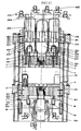
- Two working cylinders A17, a ring- toothed cylinder C17 and two stripping cylinders E17 are integrated in the traverse 2 .
- the two double-acting working cylinders A17 are arranged laterally in the cross arm 2 .
- the lower piston A17.2 forms together with the cylinder housing 2 (here designed as a traverse) the lower cylinder space A17.3.
- the upper cylinder space A17.4 is formed by the cylinder housing 2 and the upper piston rod A17.5 .
- the two lower piston rods A17.2 are firmly connected to the upper crosshead 4.1 via connecting elements A17.9 .
- the two upper piston rods A17.5 are connected to a plate that is designed as a hydraulic distributor block A17.10 .
- the double-acting ring tooth cylinder C17 is arranged in the middle between the working cylinders A17 .
- the lower piston C17.1 forms together with the cylinder housing 2 the lower cylinder space C17.2.
- the upper cylinder chamber C17.4 is formed by the cylinder housing 2 and the upper piston rod C17.5 .
- a plate E17.4 on which the pressure bolts 9 are supported is attached to the ring- toothed cylinder piston C17.1 .
- the scraper cylinders E17 are integrated in the piston A17.2 .
- the two support cylinders E17 arranged on the side can hydraulically compensate for eccentric loads on the ring spike forces.
- the ram plate 1 forms the press ram with the plates 3 ' and the cross member 2 .
- the counter-holding cylinder D17 is arranged below the plunger plate 1 in the lower crosshead of the stand 4 .
- the two side cylinders F17 can hydraulically compensate for eccentric loads on the counter-holding forces.
- the discharge cylinders F17 are attached to the plunger plate 1 .
- the stand 4 is not used by the work force of the working cylinders A17 .
- a fineblanking press as described in FIG. 17, is shown, wherein the movable and fixed machine components have been reversed.
- the ram plate 1 ' is firmly connected to the machine stand, and the function of the press ram is taken over by the movable ram 4.1' .
- the ram plate 1 ', the crossbeam A19.1 and the plates 3' are firmly connected to one another, together they form the stand of the fineblanking press .
- the plates 3 ' are extended downwards over the ram plates 1' and form the foot of the stand in the region 3.2 ' . With the traverse A19.1 , the housing of the two working cylinders A19 and the housing of the ring prong cylinder C19 are firmly connected to the stand.
- the two lower piston rods A19.2 of the working cylinders A19 are fastened to the movable plunger 4.1 ' by connecting elements A19.9 .
- the piston rod C19.1 of the serrated cylinder C19 is connected to the plunger 4.1 ' via the plate E19.4 by hydraulic coupling of the support cylinder E19 .
- the cylinder housing D19.6 of the counter-holding cylinder D19 is firmly connected below the tappet plate 1 ' to the movably arranged crossbar D19.9 .
- the ram 4.1 ' and the crossbar D19.9 are connected to each other by the plates 4' and connecting elements D19.8 . Instead of the plates 3 ', 4' , columns could also be used.
- the delivery cylinders G19 are attached with their cylinder housings to the plates 3 ' with the piston rods on the plunger 4.1' .
- the plunger G19 4.1 'and integral with this housing is moved D19.6 of the counter-holder cylinder D19 downward.
- the pressure medium is shifted from the upper cylinder rooms to the lower cylinder rooms.
Landscapes
- Engineering & Computer Science (AREA)
- Mechanical Engineering (AREA)
- Physics & Mathematics (AREA)
- Fluid Mechanics (AREA)
- Press Drives And Press Lines (AREA)
- Control Of Presses (AREA)
- Treatments For Attaching Organic Compounds To Fibrous Goods (AREA)
- Executing Machine-Instructions (AREA)
- Centrifugal Separators (AREA)
- Shearing Machines (AREA)
Applications Claiming Priority (3)
| Application Number | Priority Date | Filing Date | Title |
|---|---|---|---|
| DE19612351 | 1996-03-28 | ||
| DE19612351 | 1996-03-28 | ||
| PCT/IB1997/000312 WO1997035675A1 (de) | 1996-03-28 | 1997-03-27 | Feinschneidpresse mit ringzacken- und gegenhalterzylinder |
Publications (2)
| Publication Number | Publication Date |
|---|---|
| EP0891235A1 EP0891235A1 (de) | 1999-01-20 |
| EP0891235B1 true EP0891235B1 (de) | 2003-10-08 |
Family
ID=7789734
Family Applications (1)
| Application Number | Title | Priority Date | Filing Date |
|---|---|---|---|
| EP97907241A Expired - Lifetime EP0891235B1 (de) | 1996-03-28 | 1997-03-27 | Feinschneidpresse mit ringzacken- und gegenhalterzylinder |
Country Status (9)
| Country | Link |
|---|---|
| US (1) | US6240818B1 (zh) |
| EP (1) | EP0891235B1 (zh) |
| JP (1) | JP2000507880A (zh) |
| KR (1) | KR20000005076A (zh) |
| CN (1) | CN1219895A (zh) |
| AT (1) | ATE251512T1 (zh) |
| DE (2) | DE19642635A1 (zh) |
| ES (1) | ES2208880T3 (zh) |
| WO (1) | WO1997035675A1 (zh) |
Cited By (2)
| Publication number | Priority date | Publication date | Assignee | Title |
|---|---|---|---|---|
| EP3115122A1 (de) | 2015-07-06 | 2017-01-11 | Feintool International Holding AG | Vorrichtung und verfahren zum abstreifen/ausstossen eines stanzgitters /innenformteils und auswerfen eines schneidteils in einer feinschneidpresse |
| EP3115190A1 (de) | 2015-07-06 | 2017-01-11 | Feintool International Holding AG | Vorrichtung und verfahren zum steuern des hauptantriebs einer feinschneidpresse |
Families Citing this family (20)
| Publication number | Priority date | Publication date | Assignee | Title |
|---|---|---|---|---|
| DE19929163C1 (de) * | 1999-06-25 | 2001-01-18 | Feintool Internat Holding Ag L | Vorrichtung zum Feinschneiden von Werkstücken aus einem Blech |
| DE10005023C2 (de) * | 2000-02-04 | 2002-11-21 | Feintool Internat Holding Ag L | Feinschneidpresse |
| JP4865963B2 (ja) * | 2001-08-06 | 2012-02-01 | 株式会社大平製作所 | 線棒材のプレス加工方法および装置 |
| DE102004006126B4 (de) * | 2004-02-07 | 2006-12-28 | Horst Baltschun | Presse mit verriegeltem Stößel |
| DE102005053350A1 (de) * | 2005-11-07 | 2007-05-10 | Schuler Pressen Gmbh & Co. Kg | Presse mit Schnittschlagdämpfung |
| JP4939173B2 (ja) * | 2006-11-01 | 2012-05-23 | しのはらプレスサービス株式会社 | 横型対向スライド式プレス機械 |
| PL2042249T3 (pl) * | 2007-09-26 | 2010-08-31 | Feintool Ip Ag | Sposób i urządzenie do wytwarzania wytłoczek o znacznie gładszej powierzchni cięcia i powiększonej powierzchni funkcjonalnej |
| DE102009017626B3 (de) * | 2009-04-16 | 2010-12-16 | Horst Baltschun | Feinschneidpresse |
| US8739697B1 (en) * | 2009-10-29 | 2014-06-03 | Us Synthetic Corporation | High pressure press with tensioning assembly and related methods |
| DE102011016669B4 (de) * | 2011-04-12 | 2016-03-24 | Schuler Pressen Gmbh | Verfahren zum Betreiben einer Presse mit Unterantrieb und danach betriebene Presse |
| EP2608299B1 (de) * | 2011-12-22 | 2014-04-09 | Feintool Intellectual Property AG | Verfahren und Vorrichtung zum Herstellen von metallischen Bipolarplatten |
| DE102012025134A1 (de) * | 2012-12-21 | 2014-06-26 | Uniflex-Hydraulik Gmbh | Umformpresse |
| DE102013001165B3 (de) * | 2013-01-23 | 2014-07-03 | Horst Baltschun | Tiefziehen und Feinschneiden mit energieeffizienter Presse |
| DE102013015180A1 (de) * | 2013-09-11 | 2015-03-12 | Webo Werkzeugbau Oberschwaben Gmbh | Verfahren und Vorrichtung zum Präzisionsschneiden von Werkstücken in einer Presse |
| EP3115120B1 (de) * | 2015-07-06 | 2018-09-05 | Feintool International Holding AG | Feinschneidpresse |
| CN105127273B (zh) * | 2015-09-30 | 2017-09-12 | 苏州索力旺新能源科技有限公司 | 一种导电片连接点冲断机构 |
| DE102015016102A1 (de) * | 2015-12-11 | 2017-06-14 | Schuler Pressen Gmbh | Feinschneidpresse |
| DE102015016149A1 (de) | 2015-12-12 | 2017-06-14 | Ulrich Keller | Hochfrequenzzylinder |
| EP3736061B1 (en) * | 2019-05-06 | 2024-08-07 | Lapmaster Wolters GmbH | Fine blanking system and method for operating the same |
| CN111572083B (zh) * | 2020-04-17 | 2021-04-13 | 江苏国力锻压机床有限公司 | 一种玻璃钢制品液压机 |
Family Cites Families (18)
| Publication number | Priority date | Publication date | Assignee | Title |
|---|---|---|---|---|
| DE1249805B (zh) * | 1967-09-14 | |||
| US2547118A (en) * | 1944-11-30 | 1951-04-03 | Baker Perkins Inc | Biscuit and like cutting and embossing machine |
| US2642138A (en) * | 1951-03-07 | 1953-06-16 | Macewka John | Hydraulically actuated press |
| CH370618A (de) * | 1959-03-04 | 1963-07-15 | Almatic Ag | Hydraulisch gesteuerte Stanzpresse |
| US3570343A (en) * | 1968-10-18 | 1971-03-16 | Dro Systems Inc Di | Structure for fine blanking |
| US3564959A (en) * | 1968-11-29 | 1971-02-23 | Aida Tekkosho Kk | Fine blanking press |
| US3611854A (en) * | 1969-10-30 | 1971-10-12 | Vitaly Konstantinovich Gilev | Compound die for punching two concentrically shaped sheet circular members from strap material in punch presses with vertical disposition of blanking planes |
| US3771396A (en) * | 1971-11-18 | 1973-11-13 | Amplex Corp | Magnetic tape press |
| CH551812A (de) * | 1972-03-03 | 1974-07-31 | Hydrel Ag | Feinstanzpresse. |
| NL7501729A (nl) * | 1975-02-14 | 1976-08-17 | Perswerk De Jong B V | Werkwijze voor het omzetten van een enkele drukkracht in afzonderlijke drukkrachten, als- mede inrichting voor het uitvoeren van de werkwijze. |
| AU571538B2 (en) * | 1983-06-28 | 1988-04-21 | Repco Ltd. | Hydraulic press |
| US4662256A (en) * | 1985-05-13 | 1987-05-05 | Rochez Bros. Inc. | Die set |
| DE3728418A1 (de) * | 1987-08-26 | 1989-03-09 | Horst Baltschun | Dynamisch vorgespannte druckmittelbetaetigte presse |
| DE3808344A1 (de) * | 1988-03-12 | 1989-09-28 | Horst Baltschun | Saeulenpresse fuer grosse aussermittige belastungen und schnittschlagdaempfung |
| US4934230A (en) * | 1988-08-24 | 1990-06-19 | Wallis Bernard J | Die stamping system |
| DE3931320C1 (zh) * | 1989-09-20 | 1991-08-08 | Feintool International Holding, Lyss, Ch | |
| US5692423A (en) * | 1995-05-09 | 1997-12-02 | Kabushiki Kaisha Fujikoshi | Vibration finishing method and apparatus for same |
| US5749279A (en) * | 1996-03-20 | 1998-05-12 | General Motors Corporation | Hydraulic punch actuator with centering apparatus |
-
1996
- 1996-10-16 DE DE19642635A patent/DE19642635A1/de not_active Withdrawn
-
1997
- 1997-03-27 ES ES97907241T patent/ES2208880T3/es not_active Expired - Lifetime
- 1997-03-27 CN CN97194980A patent/CN1219895A/zh active Pending
- 1997-03-27 AT AT97907241T patent/ATE251512T1/de not_active IP Right Cessation
- 1997-03-27 EP EP97907241A patent/EP0891235B1/de not_active Expired - Lifetime
- 1997-03-27 KR KR1019980707706A patent/KR20000005076A/ko not_active Application Discontinuation
- 1997-03-27 DE DE59710835T patent/DE59710835D1/de not_active Expired - Fee Related
- 1997-03-27 WO PCT/IB1997/000312 patent/WO1997035675A1/de active IP Right Grant
- 1997-03-27 US US09/155,434 patent/US6240818B1/en not_active Expired - Fee Related
- 1997-03-27 JP JP9534190A patent/JP2000507880A/ja not_active Ceased
Cited By (4)
| Publication number | Priority date | Publication date | Assignee | Title |
|---|---|---|---|---|
| EP3115122A1 (de) | 2015-07-06 | 2017-01-11 | Feintool International Holding AG | Vorrichtung und verfahren zum abstreifen/ausstossen eines stanzgitters /innenformteils und auswerfen eines schneidteils in einer feinschneidpresse |
| EP3115190A1 (de) | 2015-07-06 | 2017-01-11 | Feintool International Holding AG | Vorrichtung und verfahren zum steuern des hauptantriebs einer feinschneidpresse |
| US10479040B2 (en) | 2015-07-06 | 2019-11-19 | Feintool International Holding Ag | Device and method for controlling the primary drive of a fine blanking press |
| US10682782B2 (en) | 2015-07-06 | 2020-06-16 | Feintool International Holding Ag | Apparatus and method for stripping away/pushing out a punched grid/internally formed part and ejecting a blanked part in a precision blanking press |
Also Published As
| Publication number | Publication date |
|---|---|
| ES2208880T3 (es) | 2004-06-16 |
| DE59710835D1 (de) | 2003-11-13 |
| DE19642635A1 (de) | 1997-10-02 |
| US6240818B1 (en) | 2001-06-05 |
| WO1997035675A1 (de) | 1997-10-02 |
| EP0891235A1 (de) | 1999-01-20 |
| ATE251512T1 (de) | 2003-10-15 |
| KR20000005076A (ko) | 2000-01-25 |
| JP2000507880A (ja) | 2000-06-27 |
| CN1219895A (zh) | 1999-06-16 |
Similar Documents
| Publication | Publication Date | Title |
|---|---|---|
| EP0891235B1 (de) | Feinschneidpresse mit ringzacken- und gegenhalterzylinder | |
| DE102007017595B3 (de) | Feinschneidpresse | |
| DE19929163C1 (de) | Vorrichtung zum Feinschneiden von Werkstücken aus einem Blech | |
| DE3036533A1 (de) | Presse zur herstellung von formkoerpern aus pulver | |
| EP3115120A1 (de) | Feinschneidpresse | |
| EP1247599A1 (de) | Antriebseinrichtung für ein Einpresswerkzeug | |
| DE102009017624B4 (de) | Tiefziehpresse | |
| WO2005075183A1 (de) | Presse mit verriegeltem stössel | |
| DE102009017626B3 (de) | Feinschneidpresse | |
| EP2719504B1 (de) | Spannvorrichtung zum Dehnen eines Gewindebolzens | |
| DE102014003229B4 (de) | Energieeffiziente vorgespannte Kompaktpresse | |
| DE10005023C2 (de) | Feinschneidpresse | |
| DE3030050A1 (de) | Lastausgleichsvorrichtung fuer pressenwerkzeuge | |
| EP0707549A1 (de) | Vorrichtung zum spannen und abfedern des leitrades von kettenfahrzeugen | |
| DE10215003A1 (de) | Hydraulische Presse | |
| DE4302263A1 (de) | Mechanische Stufenpresse mit hydraulischen Arbeitshubeinheiten | |
| DD158750A5 (de) | Schnellaufende schmiedemaschine | |
| DE2128867A1 (de) | Überlastungssicherung für die Antriebselemente von Pressen | |
| DE3025157A1 (de) | Spannelemente, insbesondere zum festspannen von werkstuecken oder werkzeugen auf werkzeugmaschinen | |
| WO2007093136A1 (de) | Hydraulische bearbeitungszange | |
| DE3915263C2 (de) | Spindelpresse | |
| DE10304052A1 (de) | Hydraulische Presse | |
| DE4419676A1 (de) | Hydraulisch gekoppelter Blechhalter | |
| DE19643396A1 (de) | Hydraulische Steuereinrichtung | |
| DE1145018B (de) | Schnellarbeitende hydraulische Presse, insbesondere Schmiedepresse oder Ziehpresse |
Legal Events
| Date | Code | Title | Description |
|---|---|---|---|
| PUAI | Public reference made under article 153(3) epc to a published international application that has entered the european phase |
Free format text: ORIGINAL CODE: 0009012 |
|
| 17P | Request for examination filed |
Effective date: 19981012 |
|
| AK | Designated contracting states |
Kind code of ref document: A1 Designated state(s): AT BE CH DE DK ES FI FR GB GR IE IT LI LU MC NL PT SE |
|
| RAP1 | Party data changed (applicant data changed or rights of an application transferred) |
Owner name: FEINTOOL INTERNATIONAL HOLDING AG |
|
| RIN1 | Information on inventor provided before grant (corrected) |
Inventor name: BALTSCHUN, HORST |
|
| 17Q | First examination report despatched |
Effective date: 20011025 |
|
| GRAH | Despatch of communication of intention to grant a patent |
Free format text: ORIGINAL CODE: EPIDOS IGRA |
|
| GRAH | Despatch of communication of intention to grant a patent |
Free format text: ORIGINAL CODE: EPIDOS IGRA |
|
| GRAA | (expected) grant |
Free format text: ORIGINAL CODE: 0009210 |
|
| RBV | Designated contracting states (corrected) |
Designated state(s): AT BE CH DE DK ES FI FR GB GR IE IT LI LU NL PT SE |
|
| AK | Designated contracting states |
Kind code of ref document: B1 Designated state(s): AT BE CH DE DK ES FI FR GB GR IE IT LI LU NL PT SE |
|
| PG25 | Lapsed in a contracting state [announced via postgrant information from national office to epo] |
Ref country code: IE Free format text: LAPSE BECAUSE OF FAILURE TO SUBMIT A TRANSLATION OF THE DESCRIPTION OR TO PAY THE FEE WITHIN THE PRESCRIBED TIME-LIMIT Effective date: 20031008 Ref country code: FI Free format text: LAPSE BECAUSE OF FAILURE TO SUBMIT A TRANSLATION OF THE DESCRIPTION OR TO PAY THE FEE WITHIN THE PRESCRIBED TIME-LIMIT Effective date: 20031008 |
|
| REG | Reference to a national code |
Ref country code: GB Ref legal event code: FG4D Free format text: NOT ENGLISH |
|
| REG | Reference to a national code |
Ref country code: CH Ref legal event code: EP |
|
| REG | Reference to a national code |
Ref country code: IE Ref legal event code: FG4D Free format text: GERMAN |
|
| REF | Corresponds to: |
Ref document number: 59710835 Country of ref document: DE Date of ref document: 20031113 Kind code of ref document: P |
|
| REG | Reference to a national code |
Ref country code: CH Ref legal event code: NV Representative=s name: FREI PATENTANWALTSBUERO |
|
| GBT | Gb: translation of ep patent filed (gb section 77(6)(a)/1977) |
Effective date: 20031203 |
|
| REG | Reference to a national code |
Ref country code: SE Ref legal event code: TRGR |
|
| PG25 | Lapsed in a contracting state [announced via postgrant information from national office to epo] |
Ref country code: GR Free format text: LAPSE BECAUSE OF FAILURE TO SUBMIT A TRANSLATION OF THE DESCRIPTION OR TO PAY THE FEE WITHIN THE PRESCRIBED TIME-LIMIT Effective date: 20040108 Ref country code: DK Free format text: LAPSE BECAUSE OF FAILURE TO SUBMIT A TRANSLATION OF THE DESCRIPTION OR TO PAY THE FEE WITHIN THE PRESCRIBED TIME-LIMIT Effective date: 20040108 |
|
| PG25 | Lapsed in a contracting state [announced via postgrant information from national office to epo] |
Ref country code: LU Free format text: LAPSE BECAUSE OF NON-PAYMENT OF DUE FEES Effective date: 20040327 |
|
| PG25 | Lapsed in a contracting state [announced via postgrant information from national office to epo] |
Ref country code: BE Free format text: LAPSE BECAUSE OF NON-PAYMENT OF DUE FEES Effective date: 20040331 |
|
| REG | Reference to a national code |
Ref country code: ES Ref legal event code: FG2A Ref document number: 2208880 Country of ref document: ES Kind code of ref document: T3 |
|
| REG | Reference to a national code |
Ref country code: IE Ref legal event code: FD4D |
|
| ET | Fr: translation filed | ||
| PLBE | No opposition filed within time limit |
Free format text: ORIGINAL CODE: 0009261 |
|
| STAA | Information on the status of an ep patent application or granted ep patent |
Free format text: STATUS: NO OPPOSITION FILED WITHIN TIME LIMIT |
|
| 26N | No opposition filed |
Effective date: 20040709 |
|
| BERE | Be: lapsed |
Owner name: *FEINTOOL INTERNATIONAL HOLDING A.G. Effective date: 20040331 |
|
| PGFP | Annual fee paid to national office [announced via postgrant information from national office to epo] |
Ref country code: SE Payment date: 20050310 Year of fee payment: 9 Ref country code: CH Payment date: 20050310 Year of fee payment: 9 |
|
| PGFP | Annual fee paid to national office [announced via postgrant information from national office to epo] |
Ref country code: FR Payment date: 20050311 Year of fee payment: 9 Ref country code: AT Payment date: 20050311 Year of fee payment: 9 |
|
| PGFP | Annual fee paid to national office [announced via postgrant information from national office to epo] |
Ref country code: GB Payment date: 20050314 Year of fee payment: 9 |
|
| PGFP | Annual fee paid to national office [announced via postgrant information from national office to epo] |
Ref country code: NL Payment date: 20050322 Year of fee payment: 9 |
|
| PGFP | Annual fee paid to national office [announced via postgrant information from national office to epo] |
Ref country code: ES Payment date: 20050323 Year of fee payment: 9 |
|
| PGFP | Annual fee paid to national office [announced via postgrant information from national office to epo] |
Ref country code: DE Payment date: 20050527 Year of fee payment: 9 |
|
| PG25 | Lapsed in a contracting state [announced via postgrant information from national office to epo] |
Ref country code: GB Free format text: LAPSE BECAUSE OF NON-PAYMENT OF DUE FEES Effective date: 20060327 Ref country code: AT Free format text: LAPSE BECAUSE OF NON-PAYMENT OF DUE FEES Effective date: 20060327 |
|
| PG25 | Lapsed in a contracting state [announced via postgrant information from national office to epo] |
Ref country code: SE Free format text: LAPSE BECAUSE OF NON-PAYMENT OF DUE FEES Effective date: 20060328 Ref country code: ES Free format text: LAPSE BECAUSE OF NON-PAYMENT OF DUE FEES Effective date: 20060328 |
|
| PG25 | Lapsed in a contracting state [announced via postgrant information from national office to epo] |
Ref country code: LI Free format text: LAPSE BECAUSE OF NON-PAYMENT OF DUE FEES Effective date: 20060331 Ref country code: CH Free format text: LAPSE BECAUSE OF NON-PAYMENT OF DUE FEES Effective date: 20060331 |
|
| PGFP | Annual fee paid to national office [announced via postgrant information from national office to epo] |
Ref country code: IT Payment date: 20060331 Year of fee payment: 10 |
|
| PG25 | Lapsed in a contracting state [announced via postgrant information from national office to epo] |
Ref country code: NL Free format text: LAPSE BECAUSE OF NON-PAYMENT OF DUE FEES Effective date: 20061001 |
|
| PG25 | Lapsed in a contracting state [announced via postgrant information from national office to epo] |
Ref country code: DE Free format text: LAPSE BECAUSE OF NON-PAYMENT OF DUE FEES Effective date: 20061003 |
|
| REG | Reference to a national code |
Ref country code: CH Ref legal event code: PL |
|
| EUG | Se: european patent has lapsed | ||
| GBPC | Gb: european patent ceased through non-payment of renewal fee |
Effective date: 20060327 |
|
| NLV4 | Nl: lapsed or anulled due to non-payment of the annual fee |
Effective date: 20061001 |
|
| REG | Reference to a national code |
Ref country code: FR Ref legal event code: ST Effective date: 20061130 |
|
| REG | Reference to a national code |
Ref country code: ES Ref legal event code: FD2A Effective date: 20060328 |
|
| PG25 | Lapsed in a contracting state [announced via postgrant information from national office to epo] |
Ref country code: PT Free format text: LAPSE BECAUSE OF NON-PAYMENT OF DUE FEES Effective date: 20040308 |
|
| PG25 | Lapsed in a contracting state [announced via postgrant information from national office to epo] |
Ref country code: FR Free format text: LAPSE BECAUSE OF NON-PAYMENT OF DUE FEES Effective date: 20060331 |
|
| PG25 | Lapsed in a contracting state [announced via postgrant information from national office to epo] |
Ref country code: IT Free format text: LAPSE BECAUSE OF NON-PAYMENT OF DUE FEES Effective date: 20070327 |