EP0886112A2 - Kombinierte Klimatisier- und Dunsthaube - Google Patents
Kombinierte Klimatisier- und Dunsthaube Download PDFInfo
- Publication number
- EP0886112A2 EP0886112A2 EP98111093A EP98111093A EP0886112A2 EP 0886112 A2 EP0886112 A2 EP 0886112A2 EP 98111093 A EP98111093 A EP 98111093A EP 98111093 A EP98111093 A EP 98111093A EP 0886112 A2 EP0886112 A2 EP 0886112A2
- Authority
- EP
- European Patent Office
- Prior art keywords
- air
- housing
- supply air
- ceiling
- fan
- Prior art date
- Legal status (The legal status is an assumption and is not a legal conclusion. Google has not performed a legal analysis and makes no representation as to the accuracy of the status listed.)
- Withdrawn
Links
- 238000004378 air conditioning Methods 0.000 title claims abstract description 6
- 239000003517 fume Substances 0.000 title abstract 2
- XLYOFNOQVPJJNP-UHFFFAOYSA-N water Substances O XLYOFNOQVPJJNP-UHFFFAOYSA-N 0.000 claims abstract description 10
- 239000002184 metal Substances 0.000 claims description 7
- 239000000284 extract Substances 0.000 claims description 6
- 239000004519 grease Substances 0.000 claims description 3
- 230000003134 recirculating effect Effects 0.000 claims description 2
- 229910052736 halogen Inorganic materials 0.000 claims 1
- 150000002367 halogens Chemical class 0.000 claims 1
- 206010020751 Hypersensitivity Diseases 0.000 abstract 1
- 208000026935 allergic disease Diseases 0.000 abstract 1
- 230000007815 allergy Effects 0.000 abstract 1
- OKTJSMMVPCPJKN-UHFFFAOYSA-N Carbon Chemical compound [C] OKTJSMMVPCPJKN-UHFFFAOYSA-N 0.000 description 4
- 239000003344 environmental pollutant Substances 0.000 description 2
- 238000001704 evaporation Methods 0.000 description 2
- 230000008020 evaporation Effects 0.000 description 2
- 238000010438 heat treatment Methods 0.000 description 2
- 231100000719 pollutant Toxicity 0.000 description 2
- 230000000630 rising effect Effects 0.000 description 2
- 230000000712 assembly Effects 0.000 description 1
- 238000000429 assembly Methods 0.000 description 1
- QVGXLLKOCUKJST-UHFFFAOYSA-N atomic oxygen Chemical compound [O] QVGXLLKOCUKJST-UHFFFAOYSA-N 0.000 description 1
- 230000015572 biosynthetic process Effects 0.000 description 1
- 238000004140 cleaning Methods 0.000 description 1
- 238000009833 condensation Methods 0.000 description 1
- 230000005494 condensation Effects 0.000 description 1
- 238000005265 energy consumption Methods 0.000 description 1
- 238000001914 filtration Methods 0.000 description 1
- 239000011521 glass Substances 0.000 description 1
- 229910052760 oxygen Inorganic materials 0.000 description 1
- 239000001301 oxygen Substances 0.000 description 1
Images

Classifications
-
- F—MECHANICAL ENGINEERING; LIGHTING; HEATING; WEAPONS; BLASTING
- F24—HEATING; RANGES; VENTILATING
- F24F—AIR-CONDITIONING; AIR-HUMIDIFICATION; VENTILATION; USE OF AIR CURRENTS FOR SCREENING
- F24F3/00—Air-conditioning systems in which conditioned primary air is supplied from one or more central stations to distributing units in the rooms or spaces where it may receive secondary treatment; Apparatus specially designed for such systems
- F24F3/12—Air-conditioning systems in which conditioned primary air is supplied from one or more central stations to distributing units in the rooms or spaces where it may receive secondary treatment; Apparatus specially designed for such systems characterised by the treatment of the air otherwise than by heating and cooling
-
- F—MECHANICAL ENGINEERING; LIGHTING; HEATING; WEAPONS; BLASTING
- F24—HEATING; RANGES; VENTILATING
- F24C—DOMESTIC STOVES OR RANGES ; DETAILS OF DOMESTIC STOVES OR RANGES, OF GENERAL APPLICATION
- F24C15/00—Details
- F24C15/20—Removing cooking fumes
-
- F—MECHANICAL ENGINEERING; LIGHTING; HEATING; WEAPONS; BLASTING
- F24—HEATING; RANGES; VENTILATING
- F24F—AIR-CONDITIONING; AIR-HUMIDIFICATION; VENTILATION; USE OF AIR CURRENTS FOR SCREENING
- F24F8/00—Treatment, e.g. purification, of air supplied to human living or working spaces otherwise than by heating, cooling, humidifying or drying
- F24F8/95—Treatment, e.g. purification, of air supplied to human living or working spaces otherwise than by heating, cooling, humidifying or drying specially adapted for specific purposes
- F24F8/96—Treatment, e.g. purification, of air supplied to human living or working spaces otherwise than by heating, cooling, humidifying or drying specially adapted for specific purposes for removing pollen
Definitions
- the invention relates to a device for air conditioning and for Removing vapors from kitchen stoves or other places or Exhaust air.
- the object of the present invention is to implement the various functions currently available different devices can be run, integrated into a single device, and to create a combination device that enables the user to make individual or all functions usable.
- the device according to the invention is a structural unit that, depending on the respective room height, immediately can be attached to the ceiling or, if the room is higher, hanging from the ceiling.
- a Such device is constructed so that all functional elements that in Combination or individually switchable, are arranged within the housing, and the housing from a floor surface facing the room, conical tapered side walls and one closing the side walls upwards Cover wall exists.
- the side walls take the openings for the circulating air, the Supply air and extract air on.
- the exhaust air part of the device has one of the bottom surface detachable grease drip tray and a exchangeable labyrinth filter and several metal filters with a large filter surface.
- the bottom of the device is, for example, funnel-shaped with a small funnel height trained, and between this funnel-shaped formation and the Fat drip tray is formed a circumferential opening gap, which is an increase the flow velocity of the air flowing through, so the performance at rising steam becomes visible.
- the supply air is fed in via a heat exchanger fed to the device. Furthermore, there is a in the housing of the device Condensed water tray provided, in the case of high condensation, the water is collected.
- the supply air is cleaned with the help of metal filters.
- the metal filters are assigned pollen filters, the pollen present in the supply air filter out.
- Ionizers are arranged below the metal filter and pollen filter electrically charge the supply air and form oxygen and charge the pollen parts that lay down on the grounded metal filters.
- the air is through the Condensed water supply moistened, so that the condensed water tray at intervals is emptied. When the device has reached a relatively high temperature, occurs heat evaporation of the condensed water.
- each of these outlets is assigned its own motor, so that the Can blow air left or right, or left and right.
- In the path of the inside the device circulating air is an arrangement of filtering purposes Activated carbon cartridges provided.
- the air circulation fans are the two of them Assigned transverse walls of the housing having air circulation openings.
- the device according to the invention has a side outlet, which with a Telescopic channel is connected.
- This telescopic channel is, for example Additional component that is supplemented with curved or straight pieces.
- the Wall connection to the engine receives several mechanical shutters with which the supply air as well as the exhaust air can be closed against cold.
- the exhaust air has two locking parts so that they can be blocked against cold when used partially. If the two exhaust air flaps are closed and the supply air flaps opened, it is possible to use the supply air as a thermal bath for heating.
- the chimney draws the supply air in the form of a vacuum requirement via the duct itself and leads the device to the corresponding air requirement.
- the device can thus in exhaust air mode, in recirculation mode, in supply air mode and in combination Exhaust air / supply air mode, recirculated air / supply air mode, recirculated air / supply air mode or Extract air / supply air + recirculation mode can be used.
- the device according to the invention is designed so that it is at a relatively low Ceiling height of e.g. 2.40 m is attached directly to the ceiling. Larger Room height, e.g. 2.60 m and above, the device is equipped with four pipes of e.g. 200 mm long attached to the ceiling.
- the device have a turntable with side channel guide, with the help of a Exhaust air duct can be installed in any direction.
- the turntable is can also be used for a direct outlet upwards, so that e.g. with sloping ceilings different heights are possible, e.g. in shape a gable roof, a glass structure or the like.
- a beam or rod goes down from which a switch box is attached.
- This control box has a number of Switches that are required for the operation of the overall device, e.g. For Light, for exhaust air in several stages, for recirculating air in e.g. two stages, for supply air and for the ionizer in the supply air path.
- the control box can also be on the wall or be attached to an upper cabinet.
- the control box is with the carrier or with the rod rotatably attached.
- the device after the Invention represents a device that has the functions of an extractor, one Air conditioner, an ionizer, and a pollen filter device, which in Kitchen area is used, and that works with overpressure in the kitchen room.
- the room conditions can be checked Mixing between exhaust air, supply air and circulating air can change, it can change the humidity of the Air can be changed by condensing, and there are multiple filters with the Device according to the invention achievable.
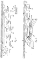
- a ceiling 1 is directly or via support tubes 2, 3 depending on the room height and Requires the housing 4 of the device according to the invention suspended from a Cover wall 5, the housing side walls 6 and the bottom wall 7.
- the two transverse side walls 6 ', 6' 'arranged opposite one another each have one Circulating air opening 8, 10 with circulating air fan 9, 11 arranged inside the housing, which suck off the air flowing into the device via the inlet air opening 12 and Dispense into the room via the air circulation openings 8, 10.
- the circulating air like that Supply air openings can be designed to be covered by blinds.
- the supply air opening 12 is assigned a supply air fan 13, from which the suctioned Air passed through the filter assemblies 14, 15 and the ionizers 16, 17 and from the Fans 9, 11 is added.
- the filter arrangements consist in detail an activated carbon filter 18 for the circulating air, large-area metal filters 19 and Labyrinth filters 20, which are assigned to a fat drain pan 21.
- the Grease drip tray 21 is preferably hinged to the bottom of the housing so that the filters can be easily removed and reinserted for cleaning can.
- Supply air 12 is arranged, which extracts the heat from the supply air and via the Filter arrangements 14, 15 and the fans 9, 11 as air 8, 10 emits into the room.
- the resulting condensate is in a condensate tray 23 collected.
- the condensed water collected is used to keep the water flowing past Humidify air so that the condensed water formed by heat evaporation is used up again and again.
- the housing 4 has a lateral outlet, which is connected to a telescopic channel 24 is connected.
- This telescopic channel 24 is an additional part with arches or straight Pieces.
- the wall connection to the motor which is an external motor, and in which also that Supply air part is provided, has mechanical closing flaps 26, 27, 28, namely for winter-summer supply air 26, and twice winter-summer exhaust air 27, 28.
- the supply air and the exhaust air can be closed twice against cold, the exhaust air has two closure parts 27, 28, so that even when used half can be shut off from the cold. If the two exhaust flaps 27, 28 closed and the flap 26 is opened for the supply air, it is possible to supply air to use as a thermal bath for heating.
- the device can only operate in exhaust air mode, only in recirculation mode, in supply air mode and in the combination exhaust air / supply air mode, Recirculated air / supply air operation or extract air / supply air + recirculated air operation can be used.
- Support rods 29 are attached to the underside 7 of the housing, the spotlights 30, Record 31, 32 for lighting. Furthermore, there is a carrier 33 on the underside 7 provided a switch box 34 with individual switches 35 for the supply air ionizer, the supply air, the recirculated air (two different positions), the exhaust air (three different positions) and the lighting.
- the control box can alternatively, however, also via a support rod on the table, on the wall or on one Wall cabinet to be attached.
- a turntable with lateral channel guidance can be provided in the middle of the device, so that the exhaust air duct can be installed in any direction.
- a such a turntable can also be used for a direct exit upwards, so that e.g. different in the case of sloping ceilings or unequal exits Column heights are possible.
Landscapes
- Engineering & Computer Science (AREA)
- Chemical & Material Sciences (AREA)
- Combustion & Propulsion (AREA)
- Mechanical Engineering (AREA)
- General Engineering & Computer Science (AREA)
- Ventilation (AREA)
- Central Air Conditioning (AREA)
Abstract
Description
- Fig. 1
- die erfindungsgemäße Vorrichtung in Seitenansicht,
- Fig. 2
- die Vorrichtung nach Fig. 1 in seitlicher Ansicht um 90° gegenüber der Darstellung nach Fig. 1 versetzt,
- Fig. 3
- eine perspektivische Ansicht der Vorrichtung von unten,
- Fig. 4
- eine Aufsicht auf die Vorrichtung nach Fig. 1 von unten,
- Fig. 5
- eine Seitenansicht einer Längsseite der Vorrichtung nach der Erfindung, und
- Fig. 6
- eine Seitenansicht einer Querseite der Vorrichtung nach der Erfindung.
Claims (9)
- Vorrichtung zum Klimatisieren der Raumluft und zum Abziehen von an Küchenherden entstehendem Dunst, dadurch gekennzeichnet, daßa) die Vorrichtung über Kopf an der Decke (1) bzw. (abhängig von der Raumhöhe) von der Decke im Abstand hängend befestigt ist,b) die Vorichtung ein sich nach oben verjüngendes Gehäuse (4) aufnimmt, in deren Seitenwänden die Zuluft-, Umluft- und Abluftöffnungen (12; 8, 10) mit jeweils einem separaten und unabhängig steuerbaren Lüfter (13; 9, 11) aufweist,c) im Luftstrom zwischen Zuluft-Lüfter (13) und Umluft-Lüfter (9, 11) Dunst-, Fett-, Pollen-Filter (14, 15; 19, 20) angeordnet sind,d) ein Wärmetauscher (22) mit Kondenswasser-Auffangschale (23) im Gehäuse (4) integriert ist, der die in der Zuluft und Abluft vorhandene Wärme in nutzbare Energie umwandelt und das aufgefangene Kondenswasser im Zuluft- und Umluftpfad so bereitstellt, daß es von dem vorbeiströmenden Luftstrom auf- und mitgenommen wird, unde) die Mittel nach a) - d) so miteinander zusammenwirken, daß die Vorrichtung als kombiniertes Dunstabzugs-Klima-Filtergerät arbeitet.
- Vorrichtung nach Anspruch 1, dadurch gekennzeichnt, daß das Gehäuse (4) ein Flachgehäuse mit einer Grundfläche von etwa l:b:h = 15:10:3 ist, das sich zur Decke hin verjüngt.
- Vorrichtung nach Anspruch 1 oder 2, dadurch gekennzeichnet, daß die Umluft- und Zuluftöffnungen (12; 8, 10) der Vorrichtung ausschließlich in den sich nach oben konisch verjüngenden Wandungen des Gehäuses ausgebildet sind.
- Vorrichtung nach einem der Ansprüche 1 - 3, dadurch gekennzeichnet, daß im Strömungspfad der Zuführluft mindestens ein Ionisator (16, 17) vorgesehen ist.
- Vorrichtung nach einem der Ansprüche 1 - 4, dadurch gekennzeichnet, daß der Dunstfilter als Metallfilter (19) mit darunter angeordneter Auffangwanne (21) angeordnet ist.
- Vorrichtung nach einem der Ansprüche 1 - 5, dadurch gekennzeichnet, daß auf der Unterseite des Gehäuses (4) in das Gehäuse integrierte und von der Gehäuseunterseite nach unten vorstehende Lampen (30, 31, 32), vorzugsweise Halogenlampen vorgesehen sind.
- Vorrichtung nach einem der Ansprüche 1 - 6, dadurch gekennzeichnet, daß auf der Gehäuseunterseite ein nach unten gerichteter Stabträger (29) befestigt ist, der einen Schaltkasten (34) mit Schaltern 35) für die gesamten Vorgänge zum Betrieb der Vorrichtung drehbar aufnimmt.
- Vorrichtung nach einem der Ansprüche 1 - 7, dadurch gekennzeichnet, daß an der Seitenwand des Gehäuses ein Abluft-Zuluft-Teleskopkanal (24) angeordnet ist.
- Vorrichtung nach Anspruch 8, dadurch gekennzeichnet, daß der Teleskopkanal (24) mechanische Verstellelemente (26, 27, 28) für die Steuerung und Umschaltung für Zuluft und Abluft aufweist.
Applications Claiming Priority (2)
| Application Number | Priority Date | Filing Date | Title |
|---|---|---|---|
| DE19725935A DE19725935A1 (de) | 1997-06-19 | 1997-06-19 | Kombinierte Klimatisier- und Dunsthaube |
| DE19725935 | 1997-06-19 |
Publications (2)
| Publication Number | Publication Date |
|---|---|
| EP0886112A2 true EP0886112A2 (de) | 1998-12-23 |
| EP0886112A3 EP0886112A3 (de) | 2002-03-06 |
Family
ID=7832950
Family Applications (1)
| Application Number | Title | Priority Date | Filing Date |
|---|---|---|---|
| EP98111093A Withdrawn EP0886112A3 (de) | 1997-06-19 | 1998-06-17 | Kombinierte Klimatisier- und Dunsthaube |
Country Status (2)
| Country | Link |
|---|---|
| EP (1) | EP0886112A3 (de) |
| DE (1) | DE19725935A1 (de) |
Cited By (4)
| Publication number | Priority date | Publication date | Assignee | Title |
|---|---|---|---|---|
| WO2003014626A1 (de) * | 2001-08-02 | 2003-02-20 | Michael Spatz | Dunstabzugshaube mit einem abluftschacht |
| WO2006045250A1 (fr) * | 2004-10-28 | 2006-05-04 | Xiuquan Wang | Hotte de conditionnement d’air pour cuisiniere dotee d’un systeme a bouclier collecteur d’air |
| CN110966671A (zh) * | 2018-09-29 | 2020-04-07 | 宁波方太厨具有限公司 | 厨房空调系统 |
| CN111720923A (zh) * | 2020-05-27 | 2020-09-29 | 华帝股份有限公司 | 一种厨房空调的控制系统及其控制方法 |
Families Citing this family (6)
| Publication number | Priority date | Publication date | Assignee | Title |
|---|---|---|---|---|
| DE10000841B4 (de) * | 2000-01-12 | 2010-03-04 | Max Homeier | Dunstabzugshaube |
| DE10020205C5 (de) * | 2000-04-25 | 2004-06-03 | Reiner Heede | Dunstabzugshaube mit Kondensatabscheider |
| DE10222407A1 (de) * | 2002-05-21 | 2003-12-11 | Bsh Bosch Siemens Hausgeraete | Dunstabzugsvorrichtung mit erweiterten Funktionen |
| DE202007002330U1 (de) | 2007-02-16 | 2007-05-10 | Homeier Küchentechnik GmbH | Vorrichtung zum Klimatisieren und Abziehen von Raumluft |
| DE102015116460A1 (de) | 2015-09-29 | 2017-03-30 | Smartcap GmbH | Vorrichtung zum Reduzieren von Geruchs-, Rauch- und/oder Dampfemissionen |
| DE102016105734A1 (de) * | 2016-03-30 | 2017-10-05 | Swiss Clean Air SLU | Kombinationsgerät für Küchen |
Family Cites Families (5)
| Publication number | Priority date | Publication date | Assignee | Title |
|---|---|---|---|---|
| US4235220A (en) * | 1979-06-07 | 1980-11-25 | Hepner Robert J | Cooking stove exhaust air filtration system |
| DE3011101C2 (de) * | 1980-03-22 | 1982-05-13 | Markus 8351 Aholming Schmalhofer | Dunstabzugshaube mit Zuluftzuführung |
| DE3502196A1 (de) * | 1985-01-24 | 1986-07-24 | Erich 7990 Friedrichshafen Mosbacher | Einrichtung zur luftversorgung eines gebaeudeinnenraumes |
| DE9101894U1 (de) * | 1991-02-19 | 1991-05-23 | Küppersbusch AG, 4650 Gelsenkirchen | Dunstabzug |
| DE4441788A1 (de) * | 1994-11-24 | 1996-05-30 | Reinhard Grunow | Dunstabzugshaube |
-
1997
- 1997-06-19 DE DE19725935A patent/DE19725935A1/de not_active Withdrawn
-
1998
- 1998-06-17 EP EP98111093A patent/EP0886112A3/de not_active Withdrawn
Cited By (5)
| Publication number | Priority date | Publication date | Assignee | Title |
|---|---|---|---|---|
| WO2003014626A1 (de) * | 2001-08-02 | 2003-02-20 | Michael Spatz | Dunstabzugshaube mit einem abluftschacht |
| WO2006045250A1 (fr) * | 2004-10-28 | 2006-05-04 | Xiuquan Wang | Hotte de conditionnement d’air pour cuisiniere dotee d’un systeme a bouclier collecteur d’air |
| CN110966671A (zh) * | 2018-09-29 | 2020-04-07 | 宁波方太厨具有限公司 | 厨房空调系统 |
| CN111720923A (zh) * | 2020-05-27 | 2020-09-29 | 华帝股份有限公司 | 一种厨房空调的控制系统及其控制方法 |
| CN111720923B (zh) * | 2020-05-27 | 2022-08-12 | 华帝股份有限公司 | 一种厨房空调的控制系统及其控制方法 |
Also Published As
| Publication number | Publication date |
|---|---|
| DE19725935A1 (de) | 1998-12-24 |
| EP0886112A3 (de) | 2002-03-06 |
Similar Documents
| Publication | Publication Date | Title |
|---|---|---|
| EP3338031B1 (de) | Kombinationsgerät mit kochfeld und dunstabzugsvorrichtung | |
| EP3338028B1 (de) | Kombinationsgerät mit kochfeld und dunstabzugsvorrichtung | |
| EP2095025B1 (de) | Dunstabsaugeinrichtung | |
| EP1194721B1 (de) | Luftabsaugvorrichtung für einen arbeitsplatz | |
| DE10020205C2 (de) | Dunstabzugshaube mit Kondensatabscheider | |
| EP3701192B1 (de) | Kombinationsgerät mit dunstabzugsvorrichtung und kochfeld | |
| EP3347651B1 (de) | Dunstabzugshaube für ein gargerät sowie gargerät mit einer solchen dunstabzugshaube | |
| EP3045824B1 (de) | Vorrichtung zum abziehen von abluft eines kochfelds | |
| DE202021004525U1 (de) | Kondensatsammelvorrichtung für Haushaltsgeräte | |
| EP0886112A2 (de) | Kombinierte Klimatisier- und Dunsthaube | |
| EP2210048B1 (de) | Dunstabzugsvorrichtung | |
| EP0633433B1 (de) | Einbauherd | |
| DE19961785A1 (de) | Dunstabzugsvorrichtung | |
| DE19950817A1 (de) | Dunstabzugsvorrichtung | |
| EP2252834A2 (de) | Dunstabzugsvorrichtung und verfahren zur reinigung von küchenluft | |
| DE10000841B4 (de) | Dunstabzugshaube | |
| DE3540263A1 (de) | Geschlossene reinraumkabine mit einer lufttechnischen anlage | |
| EP4165349A1 (de) | Dunstabzugsvorrichtung und küchenanordnung mit kochfeld und dunstabzugsvorrichtung | |
| DE102022131774B4 (de) | Dunstabzugseinrichtung | |
| DE10135842B4 (de) | Opferlichtständer | |
| EP0945684A2 (de) | Vorrichtung zum Backen und Kochen | |
| DE10216011A1 (de) | Koch- oder Grillvorrichtung | |
| DE19739863A1 (de) | Dunstabzugshaube | |
| DE102004062863A1 (de) | Vorrichtung zum Abführen eines gashaltigen oder gasförmigen Fluids aus einem Gebäuderaum | |
| DE20221503U1 (de) | Koch- oder Grillvorrichtung |
Legal Events
| Date | Code | Title | Description |
|---|---|---|---|
| PUAI | Public reference made under article 153(3) epc to a published international application that has entered the european phase |
Free format text: ORIGINAL CODE: 0009012 |
|
| AK | Designated contracting states |
Kind code of ref document: A2 Designated state(s): AT BE CH CY DE DK ES FI FR GB GR IE IT LI LU MC NL PT SE |
|
| AX | Request for extension of the european patent |
Free format text: AL;LT;LV;MK;RO;SI |
|
| PUAL | Search report despatched |
Free format text: ORIGINAL CODE: 0009013 |
|
| AK | Designated contracting states |
Kind code of ref document: A3 Designated state(s): AT BE CH CY DE DK ES FI FR GB GR IE IT LI LU MC NL PT SE |
|
| AX | Request for extension of the european patent |
Free format text: AL;LT;LV;MK;RO;SI |
|
| RIC1 | Information provided on ipc code assigned before grant |
Free format text: 7F 24F 3/12 A, 7F 24C 15/20 B |
|
| AKX | Designation fees paid | ||
| REG | Reference to a national code |
Ref country code: DE Ref legal event code: 8566 |
|
| STAA | Information on the status of an ep patent application or granted ep patent |
Free format text: STATUS: THE APPLICATION IS DEEMED TO BE WITHDRAWN |
|
| 18D | Application deemed to be withdrawn |
Effective date: 20020907 |