EP0886112A2 - Combined fume extracting and air-conditioning hood - Google Patents
Combined fume extracting and air-conditioning hood Download PDFInfo
- Publication number
- EP0886112A2 EP0886112A2 EP98111093A EP98111093A EP0886112A2 EP 0886112 A2 EP0886112 A2 EP 0886112A2 EP 98111093 A EP98111093 A EP 98111093A EP 98111093 A EP98111093 A EP 98111093A EP 0886112 A2 EP0886112 A2 EP 0886112A2
- Authority
- EP
- European Patent Office
- Prior art keywords
- air
- housing
- supply air
- ceiling
- supply
- Prior art date
- Legal status (The legal status is an assumption and is not a legal conclusion. Google has not performed a legal analysis and makes no representation as to the accuracy of the status listed.)
- Withdrawn
Links
Images

Classifications
-
- F—MECHANICAL ENGINEERING; LIGHTING; HEATING; WEAPONS; BLASTING
- F24—HEATING; RANGES; VENTILATING
- F24F—AIR-CONDITIONING; AIR-HUMIDIFICATION; VENTILATION; USE OF AIR CURRENTS FOR SCREENING
- F24F3/00—Air-conditioning systems in which conditioned primary air is supplied from one or more central stations to distributing units in the rooms or spaces where it may receive secondary treatment; Apparatus specially designed for such systems
- F24F3/12—Air-conditioning systems in which conditioned primary air is supplied from one or more central stations to distributing units in the rooms or spaces where it may receive secondary treatment; Apparatus specially designed for such systems characterised by the treatment of the air otherwise than by heating and cooling
-
- F—MECHANICAL ENGINEERING; LIGHTING; HEATING; WEAPONS; BLASTING
- F24—HEATING; RANGES; VENTILATING
- F24C—DOMESTIC STOVES OR RANGES ; DETAILS OF DOMESTIC STOVES OR RANGES, OF GENERAL APPLICATION
- F24C15/00—Details
- F24C15/20—Removing cooking fumes
-
- F—MECHANICAL ENGINEERING; LIGHTING; HEATING; WEAPONS; BLASTING
- F24—HEATING; RANGES; VENTILATING
- F24F—AIR-CONDITIONING; AIR-HUMIDIFICATION; VENTILATION; USE OF AIR CURRENTS FOR SCREENING
- F24F8/00—Treatment, e.g. purification, of air supplied to human living or working spaces otherwise than by heating, cooling, humidifying or drying
- F24F8/95—Treatment, e.g. purification, of air supplied to human living or working spaces otherwise than by heating, cooling, humidifying or drying specially adapted for specific purposes
- F24F8/96—Treatment, e.g. purification, of air supplied to human living or working spaces otherwise than by heating, cooling, humidifying or drying specially adapted for specific purposes for removing pollen
Definitions
- the invention relates to a device for air conditioning and for Removing vapors from kitchen stoves or other places or Exhaust air.
- the object of the present invention is to implement the various functions currently available different devices can be run, integrated into a single device, and to create a combination device that enables the user to make individual or all functions usable.
- the device according to the invention is a structural unit that, depending on the respective room height, immediately can be attached to the ceiling or, if the room is higher, hanging from the ceiling.
- a Such device is constructed so that all functional elements that in Combination or individually switchable, are arranged within the housing, and the housing from a floor surface facing the room, conical tapered side walls and one closing the side walls upwards Cover wall exists.
- the side walls take the openings for the circulating air, the Supply air and extract air on.
- the exhaust air part of the device has one of the bottom surface detachable grease drip tray and a exchangeable labyrinth filter and several metal filters with a large filter surface.
- the bottom of the device is, for example, funnel-shaped with a small funnel height trained, and between this funnel-shaped formation and the Fat drip tray is formed a circumferential opening gap, which is an increase the flow velocity of the air flowing through, so the performance at rising steam becomes visible.
- the supply air is fed in via a heat exchanger fed to the device. Furthermore, there is a in the housing of the device Condensed water tray provided, in the case of high condensation, the water is collected.
- the supply air is cleaned with the help of metal filters.
- the metal filters are assigned pollen filters, the pollen present in the supply air filter out.
- Ionizers are arranged below the metal filter and pollen filter electrically charge the supply air and form oxygen and charge the pollen parts that lay down on the grounded metal filters.
- the air is through the Condensed water supply moistened, so that the condensed water tray at intervals is emptied. When the device has reached a relatively high temperature, occurs heat evaporation of the condensed water.
- each of these outlets is assigned its own motor, so that the Can blow air left or right, or left and right.
- In the path of the inside the device circulating air is an arrangement of filtering purposes Activated carbon cartridges provided.
- the air circulation fans are the two of them Assigned transverse walls of the housing having air circulation openings.
- the device according to the invention has a side outlet, which with a Telescopic channel is connected.
- This telescopic channel is, for example Additional component that is supplemented with curved or straight pieces.
- the Wall connection to the engine receives several mechanical shutters with which the supply air as well as the exhaust air can be closed against cold.
- the exhaust air has two locking parts so that they can be blocked against cold when used partially. If the two exhaust air flaps are closed and the supply air flaps opened, it is possible to use the supply air as a thermal bath for heating.
- the chimney draws the supply air in the form of a vacuum requirement via the duct itself and leads the device to the corresponding air requirement.
- the device can thus in exhaust air mode, in recirculation mode, in supply air mode and in combination Exhaust air / supply air mode, recirculated air / supply air mode, recirculated air / supply air mode or Extract air / supply air + recirculation mode can be used.
- the device according to the invention is designed so that it is at a relatively low Ceiling height of e.g. 2.40 m is attached directly to the ceiling. Larger Room height, e.g. 2.60 m and above, the device is equipped with four pipes of e.g. 200 mm long attached to the ceiling.
- the device have a turntable with side channel guide, with the help of a Exhaust air duct can be installed in any direction.
- the turntable is can also be used for a direct outlet upwards, so that e.g. with sloping ceilings different heights are possible, e.g. in shape a gable roof, a glass structure or the like.
- a beam or rod goes down from which a switch box is attached.
- This control box has a number of Switches that are required for the operation of the overall device, e.g. For Light, for exhaust air in several stages, for recirculating air in e.g. two stages, for supply air and for the ionizer in the supply air path.
- the control box can also be on the wall or be attached to an upper cabinet.
- the control box is with the carrier or with the rod rotatably attached.
- the device after the Invention represents a device that has the functions of an extractor, one Air conditioner, an ionizer, and a pollen filter device, which in Kitchen area is used, and that works with overpressure in the kitchen room.
- the room conditions can be checked Mixing between exhaust air, supply air and circulating air can change, it can change the humidity of the Air can be changed by condensing, and there are multiple filters with the Device according to the invention achievable.
- a ceiling 1 is directly or via support tubes 2, 3 depending on the room height and Requires the housing 4 of the device according to the invention suspended from a Cover wall 5, the housing side walls 6 and the bottom wall 7.
- the two transverse side walls 6 ', 6' 'arranged opposite one another each have one Circulating air opening 8, 10 with circulating air fan 9, 11 arranged inside the housing, which suck off the air flowing into the device via the inlet air opening 12 and Dispense into the room via the air circulation openings 8, 10.
- the circulating air like that Supply air openings can be designed to be covered by blinds.
- the supply air opening 12 is assigned a supply air fan 13, from which the suctioned Air passed through the filter assemblies 14, 15 and the ionizers 16, 17 and from the Fans 9, 11 is added.
- the filter arrangements consist in detail an activated carbon filter 18 for the circulating air, large-area metal filters 19 and Labyrinth filters 20, which are assigned to a fat drain pan 21.
- the Grease drip tray 21 is preferably hinged to the bottom of the housing so that the filters can be easily removed and reinserted for cleaning can.
- Supply air 12 is arranged, which extracts the heat from the supply air and via the Filter arrangements 14, 15 and the fans 9, 11 as air 8, 10 emits into the room.
- the resulting condensate is in a condensate tray 23 collected.
- the condensed water collected is used to keep the water flowing past Humidify air so that the condensed water formed by heat evaporation is used up again and again.
- the housing 4 has a lateral outlet, which is connected to a telescopic channel 24 is connected.
- This telescopic channel 24 is an additional part with arches or straight Pieces.
- the wall connection to the motor which is an external motor, and in which also that Supply air part is provided, has mechanical closing flaps 26, 27, 28, namely for winter-summer supply air 26, and twice winter-summer exhaust air 27, 28.
- the supply air and the exhaust air can be closed twice against cold, the exhaust air has two closure parts 27, 28, so that even when used half can be shut off from the cold. If the two exhaust flaps 27, 28 closed and the flap 26 is opened for the supply air, it is possible to supply air to use as a thermal bath for heating.
- the device can only operate in exhaust air mode, only in recirculation mode, in supply air mode and in the combination exhaust air / supply air mode, Recirculated air / supply air operation or extract air / supply air + recirculated air operation can be used.
- Support rods 29 are attached to the underside 7 of the housing, the spotlights 30, Record 31, 32 for lighting. Furthermore, there is a carrier 33 on the underside 7 provided a switch box 34 with individual switches 35 for the supply air ionizer, the supply air, the recirculated air (two different positions), the exhaust air (three different positions) and the lighting.
- the control box can alternatively, however, also via a support rod on the table, on the wall or on one Wall cabinet to be attached.
- a turntable with lateral channel guidance can be provided in the middle of the device, so that the exhaust air duct can be installed in any direction.
- a such a turntable can also be used for a direct exit upwards, so that e.g. different in the case of sloping ceilings or unequal exits Column heights are possible.
Landscapes
- Engineering & Computer Science (AREA)
- Chemical & Material Sciences (AREA)
- Combustion & Propulsion (AREA)
- Mechanical Engineering (AREA)
- General Engineering & Computer Science (AREA)
- Ventilation (AREA)
- Central Air Conditioning (AREA)
Abstract
Description
Die Erfindung betrifft eine Vorrichtung zum Klimatisieren der Raumluft und zum Abziehen von an Küchenherden oder anderen Stellen entstehendem Dunst bzw. Abluft.The invention relates to a device for air conditioning and for Removing vapors from kitchen stoves or other places or Exhaust air.
Es gibt Klimaanlagen, die ein gesamtes Haus oder Teile eines Hauses klimatisieren. Derartige Anlagen stellen einen sehr hohen Aufwand verbunden mit einem hohen Energieverbrauch dar. Des weiteren gibt es Klimageräte, die innerhalb eines Raumes als Einzelgeräte betrieben werden. Schließlich gibt es die unterschiedlichsten Ausführungsformen von Dunstabzugshauben, die über der Dunstquelle, in der Regel einem Küchenherd angeordnet sind und den vom Herd aufsteigenden Dunst unmittelbar an der Haubenunterseite ansaugen. Schließlich existieren auch Filtergeräte, die Zuluft ansaugen und z.B. aus dieser Zuluft bestimmte Schadstoffe, wie z.B. Pollen herausfiltern. Daneben existieren Geräte, wie Ionisatoren, die die Zuluft elektrisch aufladen und bestimmte Schadstoffe in der Zuluft an geerdeten Filtern absondern.There are air conditioners that air condition an entire house or parts of a house. Such systems represent a very high outlay associated with a high level Energy consumption represents. Furthermore, there are air conditioners inside a room be operated as individual devices. After all, there are many different types Embodiments of extractor hoods that are above the source of the vapor, as a rule a kitchen stove are arranged and the haze rising from the stove Aspirate directly on the underside of the hood. After all, too Filter devices that suck in air and e.g. certain pollutants from this supply air, such as e.g. Filter out pollen. There are also devices, such as ionizers, that supply air charge electrically and certain pollutants in the supply air on earthed filters secrete.
Damit ist es erforderlich, daß der Benutzer, der die unterschiedlichen Funktionen dieser Geräte nutzen will, mehrere Einzelgeräte anschafft und aufstellt, was einen erheblichen finanziellen, aber auch räumlichen Aufwand bedeutet.This requires that the user perform the various functions who wants to use devices, purchases several individual devices and sets up what one considerable financial, but also spatial effort.
Aufgabe vorliegender Erfindung ist es, die verschiedenen Funktionen, die derzeit von unterschiedlichen Geräten ausgeführt werden, in ein einziges Gerät zu integrieren, und damit ein Kombinationsgerät zu schaffen, das den Benutzer in die Lage versetzt, einzelne oder alle Funktionen wahlweise nutzbar zu machen.The object of the present invention is to implement the various functions currently available different devices can be run, integrated into a single device, and to create a combination device that enables the user to make individual or all functions usable.
Gemäß der Erfindung wird dies mit den Merkmalen des Kennzeichens des Anspruches
1 erreicht. Weitere Ausgestaltungen der Erfindung sind Gegenstand der
Unteransprüche. According to the invention, this is with the features of the characterizing part of the
Die erfindungsgemäße Vorrichtung, die die verschiedenen Funktionen in einem Gerät vereinigt, ist eine Baueinheit, die, je nach der jeweiligen Raumhöhe, unmittelbar an der Decke oder bei größerer Raumhöhe von der Decke hängend befestigbar ist. Eine derartige Vorrichtung ist so aufgebaut, daß sämtliche Funktionselemente, die in Kombination oder einzeln schaltbar sind, innerhalb des Gehäuses angeordnet sind, und das Gehäuse aus einer dem Raum zugewandten Bodenfläche, sich konisch verjüngenden Seitenwänden und einer die Seitenwände nach oben abschließenden Deckwand besteht. Die Seitenwände nehmen dabei die Öffnungen für die Umluft, die Zuluft und die Abluft auf. Der Abluftteil der Vorrichtung weist eine der Bodenfläche des Gehäuses zugeordnete abnehmbare Fettauffangschale sowie einen auswechselbaren Labyrinthfilter und mehrere Metallfilter mit großer Filterfläche auf. Der Boden der Vorrichtung ist beispielsweise trichterförmig mit geringer Trichterhöhe ausgebildet, und zwischen dieser trichterförmigen Ausbildung und der Fettauffangsschale ist ein umlaufender Öffnungsspalt ausgebildet, der eine Erhöhung der Strömungsgeschwindigkeit der durchströmenden Luft ergibt, damit die Leistung bei aufsteigendem Dampf sichtbar wird.The device according to the invention, the different functions in one device united, is a structural unit that, depending on the respective room height, immediately can be attached to the ceiling or, if the room is higher, hanging from the ceiling. A Such device is constructed so that all functional elements that in Combination or individually switchable, are arranged within the housing, and the housing from a floor surface facing the room, conical tapered side walls and one closing the side walls upwards Cover wall exists. The side walls take the openings for the circulating air, the Supply air and extract air on. The exhaust air part of the device has one of the bottom surface detachable grease drip tray and a exchangeable labyrinth filter and several metal filters with a large filter surface. The bottom of the device is, for example, funnel-shaped with a small funnel height trained, and between this funnel-shaped formation and the Fat drip tray is formed a circumferential opening gap, which is an increase the flow velocity of the air flowing through, so the performance at rising steam becomes visible.
Die Zuluft wird bei der erfindungsgemäßen Vorrichtung über einen Wärmetauscher in der Vorrichtung zugeführt. Des weiteren ist im Gehäuse der Vorrichtung eine Kondenswasserschale vorgesehen, in der bei hohem Kondenswasseranfall das Wasser gesammelt wird. Die Zuluft wird mit Hilfe von Metallfiltern gereinigt. Vorzugsweise sind den Metallfiltern Pollenfilter zugeordnet, die in der Zuluft vorhandene Pollen ausfiltern. Unterhalb der Metallfilter und Pollenfilter sind Ionisatoren angeordnet, die die Zuluft elektrisch aufladen und Sauerstoff bilden sowie die Pollenteile aufladen, die sich an den geerdeten Metallfiltern ablegen. Gleichzeitig wird die Luft durch den Kondenswasservorrat befeuchtet, so daß die Kondenswasserschale in Abständen entleert wird. Wenn die Vorrichtung eine relativ hohe Temperatur erreicht hat, tritt auch eine Wärmeverdampfung des Kondenswassers auf.In the device according to the invention, the supply air is fed in via a heat exchanger fed to the device. Furthermore, there is a in the housing of the device Condensed water tray provided, in the case of high condensation, the water is collected. The supply air is cleaned with the help of metal filters. Preferably the metal filters are assigned pollen filters, the pollen present in the supply air filter out. Ionizers are arranged below the metal filter and pollen filter electrically charge the supply air and form oxygen and charge the pollen parts that lay down on the grounded metal filters. At the same time, the air is through the Condensed water supply moistened, so that the condensed water tray at intervals is emptied. When the device has reached a relatively high temperature, occurs heat evaporation of the condensed water.
An den beiden Querseiten des Vorrichtungsgehäuses ist jeweils ein Auslaß für die Umluft vorgesehen. Jedem dieser Auslässe ist ein eigener Motor zugeordnet, so daß die Umluft links oder rechts, oder links und rechts ausblasen kann. Im Pfad der innerhalb der Vorrichtung strömenden Umluft ist zu Filterungszwecken eine Anordnung aus Aktivkohle-kassetten vorgesehen. Die Umluftlüfter sind den beiden die Umluftöffnungen aufweisenden Querwänden des Gehäuses zugeordnet.There is an outlet for each on the two transverse sides of the device housing Forced air provided. Each of these outlets is assigned its own motor, so that the Can blow air left or right, or left and right. In the path of the inside the device circulating air is an arrangement of filtering purposes Activated carbon cartridges provided. The air circulation fans are the two of them Assigned transverse walls of the housing having air circulation openings.
Die Vorrichtung nach der Erfindung weist einen seitlichen Auslaß auf, der mit einem Teleskopkanal verbunden wird. Dieser Teleskopkanal ist beispielsweise ein Zusatzbauteil, das mit bogenförmigen oder geraden Stücken ergänzt wird. Der Wandanschluß zum Motor erhält mehrere mechanische Verschlußklappen, mit denen die Zuluft wie auch die Abluft gegen Kälte geschlossen werden kann. Die Abluft besitzt zwei Verschlußteile, damit sie bei Teilbenutzung gegen Kälte abgesperrt werden kann. Werden die beiden Abluftklappen geschlossen und die Zuluftklappen geöffnet, ist es möglich, die Zuluft als Therme für die Heizung zu nutzen. Der Ofen bzw. der offene Kamin holt sich die Zuluft in Form von Unterdruckbedarf über den Kanal selbst und führt der Vorrichtung den entsprechenden Luftbedarf zu. Die Vorrichtung kann somit im Abluftbetrieb, im Umluftbetrieb, im Zuluftbetrieb und in der Kombination Abluft/Zuluft - Betrieb, Umluft/Zuluft -Betrieb, Umluft/Zuluft - Betrieb oder Abluft/Zuluft- + Umluft - Betrieb eingesetzt werden.The device according to the invention has a side outlet, which with a Telescopic channel is connected. This telescopic channel is, for example Additional component that is supplemented with curved or straight pieces. Of the Wall connection to the engine receives several mechanical shutters with which the supply air as well as the exhaust air can be closed against cold. The exhaust air has two locking parts so that they can be blocked against cold when used partially. If the two exhaust air flaps are closed and the supply air flaps opened, it is possible to use the supply air as a thermal bath for heating. The oven or the open one The chimney draws the supply air in the form of a vacuum requirement via the duct itself and leads the device to the corresponding air requirement. The device can thus in exhaust air mode, in recirculation mode, in supply air mode and in combination Exhaust air / supply air mode, recirculated air / supply air mode, recirculated air / supply air mode or Extract air / supply air + recirculation mode can be used.
Die erfindungsgemäße Vorrichtung ist so ausgebildet, daß sie bei einer relativ geringen Raumhöhe von z.B. 2,40 m unmittelbar an der Raumdecke befestigt wird. Bei größerer Raumhöhe, z.B. 2,60 m und darüber, wird die Vorrichtung mit vier Rohren von z.B. 200 mm Länge im Abstand zur Decke befestigt. Beispielsweise kann die Vorrichtung einen Drehteller mit seitlicher Kanalführung aufweisen, mit dessen Hilfe eine Abluftführung in beliebigen Richtungen montiert werden kann. Der Drehteller ist ferner für einen direkten Abgang nach oben einsetzbar, so daß z.B. bei Dachschrägen oder ungleichen Ausgängen unterschiedliche Säulenhöhen möglich sind, z.B. in Form eines Satteldaches, einer Glaskonstruktion oder dergl.The device according to the invention is designed so that it is at a relatively low Ceiling height of e.g. 2.40 m is attached directly to the ceiling. Larger Room height, e.g. 2.60 m and above, the device is equipped with four pipes of e.g. 200 mm long attached to the ceiling. For example, the device have a turntable with side channel guide, with the help of a Exhaust air duct can be installed in any direction. The turntable is can also be used for a direct outlet upwards, so that e.g. with sloping ceilings different heights are possible, e.g. in shape a gable roof, a glass structure or the like.
Vom Boden des Gehäuses der Vorrichtung geht nach unten ein Träger bzw. ein Stanb aus, an dem ein Schaltkasten befestigt ist. Dieser Schaltkasten weist eine Anzahl von Schaltern auf, die für den Betrieb der Gesamtvorrichtung erforderlich sind, z.B. für Licht, für Abluft in mehreren Stufen, für Umluft in z.B. zwei Stufen, für Zuluft und für den Ionisator im Zuluftpfad. Alternativ kann der Schaltkasten auch an der Wand oder an einem Oberschrank befestigt sein. Der Schaltkasten ist mit dem Träger bzw. mit dem Stab drehbar befestigt.From the bottom of the housing of the device, a beam or rod goes down from which a switch box is attached. This control box has a number of Switches that are required for the operation of the overall device, e.g. For Light, for exhaust air in several stages, for recirculating air in e.g. two stages, for supply air and for the ionizer in the supply air path. Alternatively, the control box can also be on the wall or be attached to an upper cabinet. The control box is with the carrier or with the rod rotatably attached.
Mit der Vorrichtung nach der Erfindung wird erreicht, daß eine Vielzahl von unterschiedlichen, entscheidend über die Funktion einer Dunstabzugshaube hinausgehenden Funktionen, für die bisher eine Mehrzahl von getrennten Geräten notwendig war, in einem einzigen Gerät kombinierbar ist, das im Prinzip eine Erweiterung einer Dunstabzugshaube darstellt, die allerdings von der Konzeption herkömmlicher Dunstabzugshauben grundlegend abweicht. Die Vorrichtung nach der Erfindung stellt ein Gerät dar, das die Funktionen eines Dunstabzugsgerätes, eines Klimagerätes, eines Ionisierungsgerätes, und eines Pollenfiltergerätes hat, das im Küchenbereich eingesetzt wird, und das mit Überdruck im Küchenraum arbeitet.With the device according to the invention it is achieved that a variety of different, crucial about the function of an extractor hood additional functions, for which previously a plurality of separate devices was necessary, can be combined in a single device, which in principle one Extension of an extractor hood represents, however, from the conception conventional extractor hoods differs fundamentally. The device after the Invention represents a device that has the functions of an extractor, one Air conditioner, an ionizer, and a pollen filter device, which in Kitchen area is used, and that works with overpressure in the kitchen room.
Mit der Vorrichtung nach der Erfindung lassen sich andere Räume außer dem Küchenbereich einbeziehen, wenn die Verbindungstüren zwischen Küche und diesen anderen Räumen geöffnet werden, es lassen sich die Raumbedingungen durch Mischen zwischen Abluft, Zuluft und Umluft verändern, es kann die Feuchtigkeit der Luft durch Kondensieren geändert werden, und es sind Mehrfachfilterungen mit der Vorrichtung nach der Erfindung erzielbar.With the device according to the invention, other spaces besides that Include the kitchen area if the connecting doors between the kitchen and this other rooms, the room conditions can be checked Mixing between exhaust air, supply air and circulating air can change, it can change the humidity of the Air can be changed by condensing, and there are multiple filters with the Device according to the invention achievable.
Nachstehend wird die Erfindung in Verbindung mit der Zeichnung anhand eines Ausführungsbeispieles erläutert. Es zeigt:
- Fig. 1
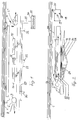
- die erfindungsgemäße Vorrichtung in Seitenansicht,
- Fig. 2
- die Vorrichtung nach Fig. 1 in seitlicher Ansicht um 90° gegenüber der Darstellung nach Fig. 1 versetzt,
- Fig. 3
- eine perspektivische Ansicht der Vorrichtung von unten,
- Fig. 4
- eine Aufsicht auf die Vorrichtung nach Fig. 1 von unten,
- Fig. 5
- eine Seitenansicht einer Längsseite der Vorrichtung nach der Erfindung, und
- Fig. 6
- eine Seitenansicht einer Querseite der Vorrichtung nach der Erfindung.
- Fig. 1
- the device according to the invention in side view,
- Fig. 2
- 1 in side view offset by 90 ° compared to the representation of FIG. 1,
- Fig. 3
- a perspective view of the device from below,
- Fig. 4
- 2 is a top view of the device according to FIG. 1,
- Fig. 5
- a side view of a long side of the device according to the invention, and
- Fig. 6
- a side view of a transverse side of the device according to the invention.
An einer Raumdecke 1 ist unmittelbar oder über Tragrohre 2, 3 je nach Raumhöhe und
Bedarf das Gehäuse 4 der erfindungsgemäßen Vorrichtung aufgehängt, das aus einer
Deckwand 5, den Gehäuseseitenwänden 6 und der Bodenwand 7 besteht. Die beiden
entgegengesetzt zueinander angeordneten Querseitenwände 6', 6'' weisen jeweils eine
Umluftöffnung 8, 10 mit im Gehäuseinneren angeordnetem Umluft-Lüfter 9, 11 auf,
die die über die Zuluftöffnung 12 in die Vorrichtung einströmende Luft absaugen und
über die Umluftöffnungen 8, 10 in den Raum abgeben. Die Umluft- wie die
Zuluftöffnungen können durch Jalousien abdeckbar ausgebildet sein.On a
Der Zuluftöffnung 12 ist ein Zuluft-Lüfter 13 zugeordnet, von dem aus die angesaugte
Luft über die Filteranordnungen 14, 15 und die Ionisatoren 16, 17 geführt und von den
Lüftern 9, 11 aufgenommen wird. Die Filteranordnungen bestehen im einzelnen aus
einem Aktivkohlefilter 18 für die Umluft, großflächigen Metallfiltern 19 und
Labyrinthfiltern 20, die einer Fettautfangschale 21 zugeordnet sind. Die
Fettauffangschale 21 ist vorzugsweise abklappbar am Gehäuseboden befestigt, so daß
die Filter zum Reinigen auf einfache Weise entnommen und wieder eingesetzt werden
können. Im oberen Teil des Gehäuses ist ein Wärmetauscher 22 im Strömungsweg der
Zuluft 12 angeordnet, der der Zuluft die Wärme entzieht und über die
Filteranordnungen 14, 15 und die Lüfter 9, 11 als Umluft 8, 10 in den Raum abgibt.
Das dabei anfallende Kondenswasser wird in einer Kondenswasserschale 23
gesammelt. Das gesammelte Kondenswasser wird verwendet, um die vorbeiströmende
Luft zu befeuchten, so daß das gebildete Kondenswasser durch Wärmeverdampfung
immer wieder aufgebraucht wird.The
Das Gehäuse 4 besitzt einen seitlichen Abgang, der mit einem Teleskopkanal 24
verbunden wird. Dieser Teleskopkanal 24 ist ein Zusatzteil mit Bögen oder geraden
Stücken. Der Wandanschluß zum Motor, der ein Außenmotor ist, und in dem auch das
Zuluftteil vorgesehen ist, weist mechanische Verschließklappen 26, 27, 28 auf,
nämlich für Winter-Sommer-Zuluft 26, sowie zweimal Winter-Sommer-Abluft 27, 28.
Dabei kann die Zuluft sowie die Abluft zweimal gegen Kälte geschlossen werden,
wobei die Abluft zwei Verschlußteile 27, 28 besitzt, damit auch bei halber Nutzung
gegen Kälte abgesperrt werden kann. Werden die beiden Abluftklappen 27, 28
geschlossen und wird die Klappe 26 für die Zuluft geöffnet, ist es möglich, die Zuluft
als Therme für die Heizung zu nutzen. Das Gerät kann somit nur im Abluftbetrieb, nur
im Umluftbetrieb, im Zuluftbetrieb sowie in der Kombination Abluft/Zuluft - Betrieb,
Umluft/Zuluft - Betrieb oder Abluft/Zuluft- + Umluft - Betrieb eingesetzt werden.The
Auf der Unterseite 7 des Gehäuses sind Tragstäbe 29 befestigt, die Strahlerlampen 30,
31, 32 für die Beleuchtung aufnehmen. Ferner ist auf der Unterseite 7 ein Träger 33
vorgesehen, der einen Schaltkasten 34 mit Einzelschaltern 35 für den Zuluft-Ionisator,
die Zuluft, die Umluft (zwei unterschiedliche Positionen), die Abluft (drei
unterschiedliche Positionen) und die Beleuchtung aufweist. Der Schaltkasten kann
alternativ jedoch auch über eine Tragstange am Tisch, an der Wand oder an einem
Oberschrank befestigt werden.
Wenn die Vorrichtung über Rohre 2, 3 als Deckenträger montiert wird, kann in der Mitte der Vorrichtung ein Drehteller mit seitlicher Kanalführung vorgesehen sein, damit die Abluftführung in einer beliebigen Richtung montiert werden kann. Ein derartiger Drehteller kann auch für einen direkten Abgang nach oben einsetzbar sein, so daß z.B. bei Dachschrägen oder ungleichen Ausgängen unterschiedliche Säulenhöhen möglich sind.If the device is mounted on pipes 2, 3 as a ceiling support, in the A turntable with lateral channel guidance can be provided in the middle of the device, so that the exhaust air duct can be installed in any direction. A such a turntable can also be used for a direct exit upwards, so that e.g. different in the case of sloping ceilings or unequal exits Column heights are possible.
Claims (9)
Applications Claiming Priority (2)
| Application Number | Priority Date | Filing Date | Title |
|---|---|---|---|
| DE19725935 | 1997-06-19 | ||
| DE19725935A DE19725935A1 (en) | 1997-06-19 | 1997-06-19 | Combined air conditioning and extractor hood |
Publications (2)
| Publication Number | Publication Date |
|---|---|
| EP0886112A2 true EP0886112A2 (en) | 1998-12-23 |
| EP0886112A3 EP0886112A3 (en) | 2002-03-06 |
Family
ID=7832950
Family Applications (1)
| Application Number | Title | Priority Date | Filing Date |
|---|---|---|---|
| EP98111093A Withdrawn EP0886112A3 (en) | 1997-06-19 | 1998-06-17 | Combined fume extracting and air-conditioning hood |
Country Status (2)
| Country | Link |
|---|---|
| EP (1) | EP0886112A3 (en) |
| DE (1) | DE19725935A1 (en) |
Cited By (4)
| Publication number | Priority date | Publication date | Assignee | Title |
|---|---|---|---|---|
| WO2003014626A1 (en) * | 2001-08-02 | 2003-02-20 | Michael Spatz | Extractor hood comprising an exhaust shaft |
| WO2006045250A1 (en) * | 2004-10-28 | 2006-05-04 | Xiuquan Wang | An air conditioning cooker hood with an air collecting shield system |
| CN110966671A (en) * | 2018-09-29 | 2020-04-07 | 宁波方太厨具有限公司 | Kitchen air conditioning system |
| CN111720923A (en) * | 2020-05-27 | 2020-09-29 | 华帝股份有限公司 | Control system and control method of kitchen air conditioner |
Families Citing this family (6)
| Publication number | Priority date | Publication date | Assignee | Title |
|---|---|---|---|---|
| DE10000841B4 (en) * | 2000-01-12 | 2010-03-04 | Max Homeier | Hood |
| DE10020205C5 (en) * | 2000-04-25 | 2004-06-03 | Reiner Heede | Extractor hood with condensate separator |
| DE10222407A1 (en) * | 2002-05-21 | 2003-12-11 | Bsh Bosch Siemens Hausgeraete | Extractor hood with extended functions |
| DE202007002330U1 (en) | 2007-02-16 | 2007-05-10 | Homeier Küchentechnik GmbH | Climate control device to control room climate and draw out air has plate form hood body with pedestal over it for connection to ceiling or wall and cover below it |
| DE102015116460A1 (en) | 2015-09-29 | 2017-03-30 | Smartcap GmbH | Device for reducing odor, smoke and / or vapor emissions |
| DE102016105734A1 (en) * | 2016-03-30 | 2017-10-05 | Swiss Clean Air SLU | Combination device for kitchens |
Citations (4)
| Publication number | Priority date | Publication date | Assignee | Title |
|---|---|---|---|---|
| US4235220A (en) * | 1979-06-07 | 1980-11-25 | Hepner Robert J | Cooking stove exhaust air filtration system |
| EP0036659A1 (en) * | 1980-03-22 | 1981-09-30 | Markus Schmalhofer | Extracting hood with fresh air intake |
| DE3502196A1 (en) * | 1985-01-24 | 1986-07-24 | Erich 7990 Friedrichshafen Mosbacher | Device for air supply of a building interior |
| DE4441788A1 (en) * | 1994-11-24 | 1996-05-30 | Reinhard Grunow | Extraction hood for cookers |
Family Cites Families (1)
| Publication number | Priority date | Publication date | Assignee | Title |
|---|---|---|---|---|
| DE9101894U1 (en) * | 1991-02-19 | 1991-05-23 | Küppersbusch AG, 4650 Gelsenkirchen | Extractor hood |
-
1997
- 1997-06-19 DE DE19725935A patent/DE19725935A1/en not_active Withdrawn
-
1998
- 1998-06-17 EP EP98111093A patent/EP0886112A3/en not_active Withdrawn
Patent Citations (4)
| Publication number | Priority date | Publication date | Assignee | Title |
|---|---|---|---|---|
| US4235220A (en) * | 1979-06-07 | 1980-11-25 | Hepner Robert J | Cooking stove exhaust air filtration system |
| EP0036659A1 (en) * | 1980-03-22 | 1981-09-30 | Markus Schmalhofer | Extracting hood with fresh air intake |
| DE3502196A1 (en) * | 1985-01-24 | 1986-07-24 | Erich 7990 Friedrichshafen Mosbacher | Device for air supply of a building interior |
| DE4441788A1 (en) * | 1994-11-24 | 1996-05-30 | Reinhard Grunow | Extraction hood for cookers |
Cited By (5)
| Publication number | Priority date | Publication date | Assignee | Title |
|---|---|---|---|---|
| WO2003014626A1 (en) * | 2001-08-02 | 2003-02-20 | Michael Spatz | Extractor hood comprising an exhaust shaft |
| WO2006045250A1 (en) * | 2004-10-28 | 2006-05-04 | Xiuquan Wang | An air conditioning cooker hood with an air collecting shield system |
| CN110966671A (en) * | 2018-09-29 | 2020-04-07 | 宁波方太厨具有限公司 | Kitchen air conditioning system |
| CN111720923A (en) * | 2020-05-27 | 2020-09-29 | 华帝股份有限公司 | Control system and control method of kitchen air conditioner |
| CN111720923B (en) * | 2020-05-27 | 2022-08-12 | 华帝股份有限公司 | Control system and control method of kitchen air conditioner |
Also Published As
| Publication number | Publication date |
|---|---|
| DE19725935A1 (en) | 1998-12-24 |
| EP0886112A3 (en) | 2002-03-06 |
Similar Documents
| Publication | Publication Date | Title |
|---|---|---|
| EP3338028B1 (en) | Combined device with cooking hob and vapour extraction unit | |
| EP3338031B1 (en) | Combined device with cooking hob and vapour extraction unit | |
| DE2825461C2 (en) | ||
| EP1194721B1 (en) | Air extraction device for a workplace | |
| DE10020205C2 (en) | Extractor hood with condensate separator | |
| WO2008058761A2 (en) | Fume extracting device | |
| CH682512A5 (en) | Steam extractor hood for cooking hob - has ventilation fan providing air curtain around hub surface to prevent mixing between steam and room air | |
| EP0886112A2 (en) | Combined fume extracting and air-conditioning hood | |
| EP2210048B1 (en) | Extractor device | |
| EP0633433B1 (en) | Built in kitchen-range | |
| DE3834440C2 (en) | Device with heat recovery for ventilation of rooms with excess heat | |
| DE19961785A1 (en) | Extractor hood | |
| EP0942235A1 (en) | Baking oven with suction casing | |
| DE2648848C2 (en) | Ventilation device for temperature control and / or exchange of air in a relatively small room | |
| EP1094278A2 (en) | Fumes evacuation device | |
| DE102011017685A1 (en) | ventilation | |
| DE10255172A1 (en) | Small-scale modular ventilation system for a single room has a basic unit with control unit, condensed water trap and an ambient air inlet/outlet pipe | |
| DE10000841B4 (en) | Hood | |
| DE3540263A1 (en) | Closed clean-room cabin with a ventilation installation | |
| WO2009106548A2 (en) | Range hood device and method for purifying kitchen air | |
| DE3913076A1 (en) | Baking room arrangement and system for ventilation - in which air is withdrawn from extract hood above baking oven, while vertical flow or fresh air is in dough prepn. | |
| EP4165349A1 (en) | Extractor apparatus, and kitchen arrangement having a hob and an extractor apparatus | |
| DE10135842B4 (en) | Votive light stand | |
| DE102022131774A1 (en) | Extractor hood, cooking system and process | |
| EP0945684A2 (en) | Apparatus for baking and cooking |
Legal Events
| Date | Code | Title | Description |
|---|---|---|---|
| PUAI | Public reference made under article 153(3) epc to a published international application that has entered the european phase |
Free format text: ORIGINAL CODE: 0009012 |
|
| AK | Designated contracting states |
Kind code of ref document: A2 Designated state(s): AT BE CH CY DE DK ES FI FR GB GR IE IT LI LU MC NL PT SE |
|
| AX | Request for extension of the european patent |
Free format text: AL;LT;LV;MK;RO;SI |
|
| PUAL | Search report despatched |
Free format text: ORIGINAL CODE: 0009013 |
|
| AK | Designated contracting states |
Kind code of ref document: A3 Designated state(s): AT BE CH CY DE DK ES FI FR GB GR IE IT LI LU MC NL PT SE |
|
| AX | Request for extension of the european patent |
Free format text: AL;LT;LV;MK;RO;SI |
|
| RIC1 | Information provided on ipc code assigned before grant |
Free format text: 7F 24F 3/12 A, 7F 24C 15/20 B |
|
| AKX | Designation fees paid | ||
| REG | Reference to a national code |
Ref country code: DE Ref legal event code: 8566 |
|
| STAA | Information on the status of an ep patent application or granted ep patent |
Free format text: STATUS: THE APPLICATION IS DEEMED TO BE WITHDRAWN |
|
| 18D | Application deemed to be withdrawn |
Effective date: 20020907 |