EP1094278A2 - Fumes evacuation device - Google Patents
Fumes evacuation device Download PDFInfo
- Publication number
- EP1094278A2 EP1094278A2 EP00122081A EP00122081A EP1094278A2 EP 1094278 A2 EP1094278 A2 EP 1094278A2 EP 00122081 A EP00122081 A EP 00122081A EP 00122081 A EP00122081 A EP 00122081A EP 1094278 A2 EP1094278 A2 EP 1094278A2
- Authority
- EP
- European Patent Office
- Prior art keywords
- supply air
- filter device
- air duct
- duct outlet
- filter
- Prior art date
- Legal status (The legal status is an assumption and is not a legal conclusion. Google has not performed a legal analysis and makes no representation as to the accuracy of the status listed.)
- Withdrawn
Links
Images
Classifications
-
- F—MECHANICAL ENGINEERING; LIGHTING; HEATING; WEAPONS; BLASTING
- F24—HEATING; RANGES; VENTILATING
- F24C—DOMESTIC STOVES OR RANGES ; DETAILS OF DOMESTIC STOVES OR RANGES, OF GENERAL APPLICATION
- F24C15/00—Details
- F24C15/20—Removing cooking fumes
- F24C15/2028—Removing cooking fumes using an air curtain
Definitions
- the invention relates to an extractor hood device according to the preamble of Claim 1.
- the invention relates to an extractor device containing a filter device, an exhaust duct and an exhaust fan through which haze through the filter device and then through the exhaust duct into the outside environment of a building is eligible.
- the extractor device can be a so-called extractor hood or a Eat for pulling kitchen vapors out of a kitchen. They are usually arranged over the hotplates of a stove.
- the filter device consists at least of a grease and dust filter, but can also contain an odor filter downstream of this filter Elimination of smells.
- odor filters mostly consist of activated carbon, however, can also be made from other materials for odor removal exist through adsorption or absorption or chemical reactions.
- Odor filters are normally only used in extractor hoods for "recirculation mode” used.
- “Circulating air mode” means that the haze is sucked out of the kitchen, cleaned by the filter device and then conveyed back to the kitchen becomes.
- extractor hoods for “exhaust air operation” there are normally no odor filters used, although this is also possible with them.
- “Exhaust air operation” means that the smells extracted from the kitchen after the filter device not back into the kitchen, but conveyed out of the building into the open become.
- DE utility model 1 987 333 is an extractor hood for recirculation mode known which a grease and dust filter, an odor filter with activated carbon to exude odors, and a fan in that order Blower flow direction has. Furthermore, from DE utility model 91 05 430.3 an extractor hood for air recirculation is known, in which a fan arranged in the flow path between a grease filter and an odor filter is. An extractor hood is from DE utility model 78 02 041 known with two fans, which either for recirculation mode or for exhaust air mode can be trained.
- extractor hoods are also known according to the preamble of claim 1, which are only designed for exhaust air operation.
- the extractor device can either only switchable for exhaust air operation or optionally for exhaust air operation or recirculation air operation be trained. You can use an odor filter in the exhaust air duct or in a recirculation air duct contain.
- Exhaust air operation has the advantage that no air is returned to the kitchen, which contains residues of haze particles or odors.
- Has exhaust air operation however the disadvantage that the exhaust fan constantly clean warm air from the kitchen exhausts and promotes the outdoors outside of the building, what in cold seasons results in increased heating costs.
- Recirculation mode has this disadvantage Not.
- Recirculating air operation has the disadvantage, however, that unpleasant residues of haze and smells from the extractor hood are conveyed back to the kitchen and that an odor filter is required in addition to the grease filter, if you at least partially remove unpleasant cooking smells from the haze would like to.
- the object of the invention is to be achieved in a simple manner with exhaust air operation and inexpensive way to reduce the proportion of clean kitchen air, from an exhaust fan along with the haze out of the kitchen the free is promoted outside of a building.
- an extractor device is characterized in that that an outside air supply air duct is provided, the at least one close to the suction side of the filter device in its suction area located supply air duct outlet, so that supply air from the outside environment of the building in the immediate suction area of the suction side the filter device is conductive, where they mix with rising vapor can and together with the haze from the exhaust fan through the filter device is absorbent.
- Haze (vapors) rising from a hotplate has a strong dynamic of its own (Kinetic energy), through which a deflection of the vapor flow by a Airflow is difficult unless a very strong airflow is used.
- the vapor flow is easily deflected by a mechanical element, for example also through the filter surfaces of the filter device, in particular from their grease filters. So that the vapor flow from the suction side of the grease filter is not mechanical distracted, but sucked as completely as possible through the grease filter a certain minimum suction power and minimum flow rate must be from the exhaust fan are generated in the filter device. Thereby creates a volume flow of air and haze, which is much larger than the volume flow of the haze alone. As a result, the exhaust fan will additionally a large proportion of the kitchen air surrounding the haze is also sucked into the haze and sucked through the filter device together with the haze.
- An essential idea of the invention then is the additional air, which for the extraction of the vapor through the filter device is required, not from the Provide kitchen, but from the outside air surrounding the kitchen building.
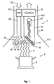
- the extractor device 2 shown schematically in vertical section in FIG. 1 is arranged above a hotplate 4, which is schematic is represented by a saucepan 6 and vapor 8 (vapors) rising from it.
- the extractor device 2 has a housing 10, which in the upper area Shaft 10-2 and in the lower area a funnel-like widening Screen 10-1 forms.
- a filter device 14 is in the flow path of the rising vapor 8 Form of a grease filter arranged obliquely, for. B. at about 45 ° like a kind Half of a saddle roof over the right half of the stream ascending Haze 8.
- the filter device 14 is located at the lower end of an exhaust air duct 16, in which an exhaust fan 18 is arranged to exhaust 20 into the outside environment or to promote the freedom of a building in which the extractor device 2 is arranged in a kitchen.
- the exhaust air 20 consists of vapor 8 (vapors) and added fresh air, hereinafter Air called 22, from the outside of the building.
- Air vapor
- the Shaft 10-2 extends parallel to the exhaust air duct 16, an inlet air duct 26 vertically downward, in which there is a supply air blower 28.
- the supply air fan 28 sucks fresh air or supply air from the outside of the building 22 and blows it from a supply air duct outlet 30, which in Fig. 1 to the left of Haze 8 is arranged over the rising haze 8 against the intake side 32 of the grease filter 14.
- the supply air 22 flows in the form of an air curtain 34 between the rising vapor 8 and the grease filter 14 against its suction side 32.
- the air curtain 34 forms a kind of left half of a gable roof, the right half is formed by the fat filter 14 above the rising haze 8.
- the supply air flow 34 flowing out of the supply air duct outlet 30 is on it Top through a diagonally upwards from the supply air duct outlet towards The upper end of the filter device 14 defines a baffle 36.
- the rising vapor stream 8 penetrates just before the intake side 32 and also on this intake side 32 into the air curtain 34 of the supply air and then together with this as exhaust air 20 from the exhaust fan 18 through the exhaust duct 16 sucked through and conveyed into the outside atmosphere of the building.
- the large kinetic energy of the vapor stream 8 can penetrate it into the Supply air close to the upstream side of the fat filter 14 also as an injection in this additional air 22, 34 are referred to.
- the supply air duct outlet 30 can be in the form of a slot nozzle or in the form of a nozzle tube with a variety be formed by nozzle bores and the supply air 22 in the form of an air curtain 34 or one extending over the entire cross section of the grease filter 14 Dispense spray onto this grease filter 14.
- This turns the haze 8 (Vapors), which is automatically by convection from the hotplate or Cooking pot 6 rises, injected into the air flow 34 of the supply air 22 and into this entrained the grease filter 14.
- the exhaust fan 18 sucks about 20% more (depending on the embodiment the extractor device and the performance of the exhaust fan 18) volume flow through the filter device 14 as supply air 22 through the supply air blower 28 is supplied, and blows the exhaust air 20 out into the outside atmosphere of the building.
- the volume of the exhaust air flow 20 is a multiple of the volume flow of the Steam is 8, this means that the flow of exhaust air 20 is almost 80% Supply air 22, and about 20% from haze 8 and little or no air from the kitchen consists.
- the exhaust air duct 16 and the supply air duct 26 can together as a heat exchanger be trained, e.g. B. separated from each other only by a heat-permeable wall be so that cold supply air 22 in the supply air duct 26 of warm exhaust air 20 in the exhaust air duct 16 is heated.
- the supply air duct outlet 30 can have an annular shape be and the path of the rising steam 8 partially or completely surround.
- the supply air blower 28 is omitted and the supply air 22 is the suction of the exhaust fan 18 on the Suction side of the filter device 14 from the outside environment of the building sucked through the supply air duct 26.
- This suction effect is then special effective if there is a lack of fresh air in the kitchen, e.g. B. all windows and doors are tightly closed.
- the supply of supply air 22 is preferably switched off, for. B. by switching off the Supply air blower 28 and / or by a closure flap for closing the supply air duct 26.
Landscapes
- Engineering & Computer Science (AREA)
- Chemical & Material Sciences (AREA)
- Combustion & Propulsion (AREA)
- Mechanical Engineering (AREA)
- General Engineering & Computer Science (AREA)
- Ventilation (AREA)
- Filtering Of Dispersed Particles In Gases (AREA)
Abstract
Description
Die Erfindung betrifft eine Dunstabzugsvorrichtung gemäß dem Oberbegriff von Anspruch 1.The invention relates to an extractor hood device according to the preamble of Claim 1.
Demgemäß betrifft die Erfindung eine Dunstabzugsvorrichtung enthaltend eine Filtervorrichtung, einen Abluftkanal und ein Abluftgebläse, durch welches Dunst durch die Filtervorrichtung und dann durch den Abluftkanal hindurch in die Außenumgebung eines Gebäudes förderbar ist.Accordingly, the invention relates to an extractor device containing a filter device, an exhaust duct and an exhaust fan through which haze through the filter device and then through the exhaust duct into the outside environment of a building is eligible.
Die Dunstabzugsvorrichtung kann eine sogenannte Dunstabzugshaube oder eine Esse sein zum Abziehen von Küchendünsten aus einer Küche. Sie sind normalerweise über den Kochstellen eines Kochherdes angeordnet.The extractor device can be a so-called extractor hood or a Eat for pulling kitchen vapors out of a kitchen. They are usually arranged over the hotplates of a stove.
Die Filtervorrichtung besteht mindestens aus einem Fett- und Staubfilter, kann jedoch auch zusätzlich stromabwärts dieses Filters einen Geruchsfilter enthalten zum Ausscheiden von Gerüchen. Solche Geruchsfilter bestehen meistens aus Aktivkohle, können jedoch auch aus anderen Materialien zum Abscheiden von Gerüchen durch Adsorption oder Absorption oder chemische Reaktionen bestehen.The filter device consists at least of a grease and dust filter, but can also contain an odor filter downstream of this filter Elimination of smells. Such odor filters mostly consist of activated carbon, however, can also be made from other materials for odor removal exist through adsorption or absorption or chemical reactions.
Geruchsfilter werden normalerweise nur in Dunstabzugshauben für "Umluftbetrieb" verwendet. "Umluftbetrieb" bedeutet, daß der Dunst aus der Küche angesaugt, durch die Filtervorrichtung gereinigt und dann wieder in die Küche zurück gefördert wird. Bei Dunstabzugshauben für "Abluftbetrieb" werden normalerweise keine Geruchsfilter verwendet, obwohl dies auch bei ihnen möglich ist. "Abluftbetrieb" bedeutet, daß die aus der Küche abgesaugten Gerüche nach der Filtervorrichtung nicht in die Küche zurück, sondern aus dem Gebäude heraus in das Freie gefördert werden. Odor filters are normally only used in extractor hoods for "recirculation mode" used. "Circulating air mode" means that the haze is sucked out of the kitchen, cleaned by the filter device and then conveyed back to the kitchen becomes. With extractor hoods for "exhaust air operation" there are normally no odor filters used, although this is also possible with them. "Exhaust air operation" means that the smells extracted from the kitchen after the filter device not back into the kitchen, but conveyed out of the building into the open become.
Aus dem DE-Gebrauchsmuster 1 987 333 ist eine Dunstabzugshaube für Umluftbetrieb bekannt, welche einen Fett- und Staubfilter, einen Geruchsfilter mit Aktivkohle zum Ausscheiden von Gerüchen, und ein Gebläse in dieser Reihenfolge in Gebläseströmungsrichtung aufweist. Ferner ist aus dem DE-Gebrauchsmuster 91 05 430.3 eine Dunstabzugshaube für Umluftbetrieb bekannt, bei welcher ein Gebläse im Strömungsweg zwischen einem Fettfilter und einem Geruchsfilter angeordnet ist. Aus dem DE-Gebrauchsmuster 78 02 041 ist eine Dunstabzugshaube mit zwei Gebläsen bekannt, welche wahlweise für Umluftbetrieb oder für Abluftbetrieb ausgebildet sein können.From DE utility model 1 987 333 is an extractor hood for recirculation mode known which a grease and dust filter, an odor filter with activated carbon to exude odors, and a fan in that order Blower flow direction has. Furthermore, from DE utility model 91 05 430.3 an extractor hood for air recirculation is known, in which a fan arranged in the flow path between a grease filter and an odor filter is. An extractor hood is from DE utility model 78 02 041 known with two fans, which either for recirculation mode or for exhaust air mode can be trained.
Ferner sind gemäß dem Oberbegriff von Anspruch 1 auch Dunstabzugshauben bekannt, welche nur für Abluftbetrieb ausgebildet sind.Furthermore, extractor hoods are also known according to the preamble of claim 1, which are only designed for exhaust air operation.
Die Dunstabzugsvorrichtung (Haube oder Esse) nach der Erfindung kann entweder nur für Abluftbetrieb oder wahlweise für Abluftbetrieb oder Umluftbetrieb umschaltbar ausgebildet sein. Sie kann im Abluftkanal oder in einem Umluftkanal einen Geruchsfilter enthalten.The extractor device (hood or cooker) according to the invention can either only switchable for exhaust air operation or optionally for exhaust air operation or recirculation air operation be trained. You can use an odor filter in the exhaust air duct or in a recirculation air duct contain.
Abluftbetrieb hat den Vorteil, daß keine Luft in die Küche zurück gefördert wird, welche Reste von Dunstpartikeln oder Gerüchen enthält. Abluftbetrieb hat jedoch den Nachteil, daß das Abluftgebläse ständig auch saubere warme Luft aus der Küche absaugt und in das Freie außerhalb des Gebäudes fördert, was in kalten Jahreszeiten erhöhte Heizkosten zur Folge hat. Diesen Nachteil hat Umluftbetrieb nicht. Umluftbetrieb hat jedoch den Nachteil, daß unangenehme Reste von Dunst und Gerüchen aus der Dunstabzugshaube wieder in die Küche zurück gefördert werden, und daß zusätzlich zum Fettfilter auch ein Geruchsfilter erforderlich ist, wenn man unangenehme Kochgerüche wenigstens teilweise aus dem Dunst entfernen möchte.Exhaust air operation has the advantage that no air is returned to the kitchen, which contains residues of haze particles or odors. Has exhaust air operation however the disadvantage that the exhaust fan constantly clean warm air from the kitchen exhausts and promotes the outdoors outside of the building, what in cold seasons results in increased heating costs. Recirculation mode has this disadvantage Not. Recirculating air operation has the disadvantage, however, that unpleasant residues of haze and smells from the extractor hood are conveyed back to the kitchen and that an odor filter is required in addition to the grease filter, if you at least partially remove unpleasant cooking smells from the haze would like to.
Durch die Erfindung soll die Aufgabe gelöst werden, bei Abluftbetrieb auf einfache und preiswerte Art und Weise den Anteil von sauberer Küchenluft zu reduzieren, der von einem Abluftgebläse zusammen mit dem Dunst aus der Küche heraus in das Freie außerhalb eines Gebäudes gefördert wird.The object of the invention is to be achieved in a simple manner with exhaust air operation and inexpensive way to reduce the proportion of clean kitchen air, from an exhaust fan along with the haze out of the kitchen the free is promoted outside of a building.
Diese Aufgabe wird gemäß der Erfindung durch die kennzeichnenden Merkmale von Anspruch 1 gelöst. This object is achieved according to the invention by the characterizing features solved by claim 1.
Demgemäß ist eine Dunstabzugsvorrichtung nach der Erfindung dadurch gekennzeichnet, daß ein Außenumgebungsluft-Zuluftkanal vorgesehen ist, der mindestens einen nahe bei der Ansaugseite der Filtervorrichtung in deren Saugbereich gelegenen Zuluftkanalauslaß aufweist, so daß Zuluft aus der Außenumgebung des Gebäudes in den unmittelbaren Ansaugbereich der Ansaugseite der Filtervorrichtung leitbar ist, wo sie mit aufsteigendem Dunst vermischen kann und zusammen mit dem Dunst von dem Abluftgebläse durch die Filtervorrichtung saugbar ist.Accordingly, an extractor device according to the invention is characterized in that that an outside air supply air duct is provided, the at least one close to the suction side of the filter device in its suction area located supply air duct outlet, so that supply air from the outside environment of the building in the immediate suction area of the suction side the filter device is conductive, where they mix with rising vapor can and together with the haze from the exhaust fan through the filter device is absorbent.
Von einer Kochstelle aufsteigender Dunst (Wrasen) hat eine starke Eigendynamik (Bewegungsenergie), durch welche eine Ablenkung des Dunststromes durch einen Luftstrom nur schwer möglich ist, außer es wird ein sehr starker Luftstrom verwendet. Der Dunststrom wird jedoch leicht durch ein mechanisches Element abgelenkt, beispielsweise auch durch die Filterflächen der Filtervorrichtung, insbesondere von deren Fettfilter. Damit der Dunststrom von der Saugseite des Fettfilters nicht mechanisch abgelenkt, sondern möglichst vollständig durch den Fettfilter hindurch gesaugt wird, muß von dem Abluftgebläse eine bestimmte Mindestsaugkraft und Mindest-Strömungsgeschwindigkeit in der Filtervorrichtung erzeugt werden. Dadurch entsteht ein Volumenstrom aus Luft und Dunst, welcher wesentlich größer ist als der Volumenstrom des Dunstes allein. Dadurch wird vom Abluftgebläse zusätzlich zu dem Dunst auch ein großer Anteil von den Dunst umgebender Küchenluft angesaugt und zusammen mit dem Dunst durch die Filtervorrichtung hindurch gesaugt.Haze (vapors) rising from a hotplate has a strong dynamic of its own (Kinetic energy), through which a deflection of the vapor flow by a Airflow is difficult unless a very strong airflow is used. The vapor flow is easily deflected by a mechanical element, for example also through the filter surfaces of the filter device, in particular from their grease filters. So that the vapor flow from the suction side of the grease filter is not mechanical distracted, but sucked as completely as possible through the grease filter a certain minimum suction power and minimum flow rate must be from the exhaust fan are generated in the filter device. Thereby creates a volume flow of air and haze, which is much larger than the volume flow of the haze alone. As a result, the exhaust fan will additionally a large proportion of the kitchen air surrounding the haze is also sucked into the haze and sucked through the filter device together with the haze.
Ein wesentlicher Gedanke der Erfindung besteht dann, die Zusatzluft, welche für das Absaugen des Dunstes durch die Filtervorrichtung erforderlich ist, nicht aus der Küche bereitzustellen, sondern von der das Küchengebäude umgebenden Außenluft.An essential idea of the invention then is the additional air, which for the extraction of the vapor through the filter device is required, not from the Provide kitchen, but from the outside air surrounding the kitchen building.
Weitere Merkmale der Erfindung sind in den Unteransprüchen enthalten.Further features of the invention are contained in the subclaims.
Die Erfindung wird im folgenden mit Bezug auf die Zeichnung anhand einer bevorzugten Ausführungsform als Beispiel beschrieben. In der Zeichnung zeigt
- Fig. 1
- schematisch im Vertikalschnitt eine Dunstabzugsvorrichtung (Haube oder Esse) nach der Erfindung.
- Fig. 1
- schematically in vertical section an extractor device (hood or cooker) according to the invention.
Die in Fig. 1 schematisch im Vertikalschnitt gezeigte Dunstabzugsvorrichtung 2
nach der Erfindung ist über einer Kochstelle 4 angeordnet, welche schematisch
durch einen Kochtopf 6 und daraus aufsteigenden Dunst 8 (Wrasen) dargestellt ist.The
Die Dunstabzugsvorrichtung 2 hat ein Gehäuse 10, welches im oberen Bereich einen
Schacht 10-2 und im unteren Bereich einen nach unten trichterartig weiter werdenden
Schirm 10-1 bildet.The
Im Strömungsweg des aufsteigenden Dunstes 8 ist eine Filtervorrichtung 14 in
Form eines Fettfilters schräg angeordnet, z. B. unter etwa 45° nach Art wie eine
Hälfte eines Satteldaches über der rechten Hälfte des Stromes an aufsteigendem
Dunst 8. Die Filtervorrichtung 14 befindet sich am unteren Ende eines Abluftkanals
16, in welchem ein Abluftgebläse 18 angeordnet ist, um Abluft 20 in die Außenumgebung
oder das Freie eines Gebäudes zu fördern, in welchem die Dunstabzugsvorrichtung
2 in einer Küche angeordnet ist.A
Die Abluft 20 besteht aus Dunst 8 (Wrasen) und hinzugefügter Frischluft, im folgenden
Zuluft 22 genannt, von der Außenumgebung des Gebäudes. Durch den
Schacht 10-2 erstreckt sich parallel neben dem Abluftkanal 16 ein Zuluftkanal 26
vertikal nach unten, in welchem sich ein Zuluftgebläse 28 befindet. Das Zuluftgebläse
28 saugt von der Außenumgebung des Gebäudes Frischluft oder Zuluft 22
an und bläst diese von einem Zuluftkanalauslaß 30, welcher in Fig. 1 links vom
Dunst 8 angeordnet ist, über den austeigenden Dunst 8 gegen die Ansaugseite 32
des Fettfilters 14. Die Zuluft 22 strömt in Form eines Luftvorhanges 34 zwischen
dem aufsteigenden Dunst 8 und dem Fettfilter 14 gegen dessen Ansaugseite 32.
Dabei bildet der Luftvorhang 34 eine Art linke Hälfte eines Satteldaches, dessen
rechte Hälfte durch den Fettfilter 14 über dem aufsteigenden Dunst 8 gebildet ist.The
Der aus dem Zuluftkanalauslaß 30 ausströmende Zuluftstrom 34 ist auf seiner
Oberseite durch ein vom Zuluftkanalauslaß schräg nach oben in Richtung zum
oberen Ende der Filtervorrichtung 14 sich erstreckendes Leitblech 36 abgrenzt.The
Der aufsteigende Dunststrom 8 dringt unmittelbar kurz vor Ansaugseite 32 und
auch an dieser Ansaugseite 32 in den Luftvorhang 34 der Zuluft ein und wird dann
zusammen mit dieser als Abluft 20 vom Abluftgebläse 18 durch den Abluftkanal 16
hindurch abgesaugt und in die Außenatmosphäre des Gebäudes gefördert. Durch
die große Bewegungsenergie des Dunststromes 8 kann dessen Eindringen in die
Zuluft dicht an der stromaufwärtigen Seite des Fettfilters 14 auch als Injizierung in
diese Zusatzluft 22, 34 bezeichnet werden.The rising
Auf diese Weise wird die zum Absaugen des Dunstes 8 erforderliche hohe Ansaugenergie
vom Abluftgebläse 18 in dem Fettfilter 14 erzeugt, ohne daß das dazu
erforderliche Luftvolumen aus der Küche abgesaugt wird.In this way, the high intake energy required to extract the
Durch das Zuluftgebläse 28 wird nicht-temperierte Außenluft des Gebäudes in das
Kanalsystem der Dunstabzugsvorrichtung 2 eingeblasen. Der Zuluftkanalauslaß 30
kann in Form einer Schlitzdüse oder in Form eines Düsenrohres mit einer Vielzahl
von Düsenbohrungen ausgebildet sein und die Zuluft 22 in Form eines Luftvorhanges
34 oder eines sich über den gesamten Querschnitt des Fettfilters 14 erstrekkenden
Sprühstrahles auf diesen Fettfilter 14 abgeben. Dadurch wird der Dunst 8
(Wrasen), welcher automatisch durch Konvektion von der Kochstelle bzw. dem
Kochtopf 6 aufsteigt, in den Luftstrom 34 der Zuluft 22 injiziert und von diesem in
den Fettfilter 14 hinein mitgerissen.Through the
Das Abluftgebläse 18 saugt etwa 20 % mehr (abhängig von der Ausführungsform
der Dunstabzugsvorrichtung und der Leistung des Abluftgebläses 18) Volumenstrom
durch die Filtervorrichtung 14 hindurch ab als Zuluft 22 durch das Zuluftgebläse
28 zugeführt wird, und bläst die Abluft 20 nach außen in die Außenatmosphäre
des Gebäudes.The
Da das Volumen des Abluftstromes 20 ein Vielfaches des Volumenstromes des
Dampfes 8 ist, bedeutet dies, daß der Strom der Abluft 20 nahezu zu 80 % aus
Zuluft 22, und etwa 20 % aus Dunst 8 und wenig oder keiner Luft aus der Küche
besteht.Since the volume of the
Damit ergeben sich für die Erfindung folgende Vorteile:This results in the following advantages for the invention:
Etwa 80 % der Abluft 20 bleibt untemperiert; es ergibt sich eine Heizenergie-Einsparung
für das Heizen der Küche bis zu etwa 80 %; eine einfache Luftführung;
sehr kundenfreundlich, weil keine Wartungsarbeiten erforderlich sind; es ist keine
teure Wärmerückgewinnungseinrichtung erforderlich.About 80% of the
Der Abluftkanal 16 und der Zuluftkanal 26 können zusammen als Wärmetauscher
ausgebildet sein, z. B. nur durch eine wärmedurchlässige Wand voneinander getrennt
sein, so daß kalte Zuluft 22 im Zuluftkanal 26 von warmer Abluft 20 im Abluftkanal
16 erwärmt wird. Ferner kann der Zuluftkanalauslaß 30 ringförmig ausgebildet
sein und den Weg des aufsteigenden Dampfes 8 teilweise oder vollständig
umgeben.The
Gemäß einer nicht gezeigten Ausführungsform ist das Zuluftgebläse 28 weggelassen
und die Zuluft 22 wird von der Saugwirkung des Abluftgebläses 18 auf der
Saugseite der Filtervorrichtung 14 aus der Außenumgebung des Gebäudes durch
den Zuluftkanal 26 hindurch angesaugt. Diese Saugwirkung ist dann besonders
wirksam, wenn in der Küche Frischluftmangel herrscht, z. B. alle Fenster und Türen
dicht verschlossen sind.According to an embodiment not shown, the
Die Zufuhr von Zuluft 22 ist vorzugsweise abschaltbar, z. B. durch Abschalten des
Zuluftgebläses 28 und/oder durch eine Verschlußklappe zum Verschließen des Zuluftkanals
26.The supply of
Claims (7)
Applications Claiming Priority (2)
| Application Number | Priority Date | Filing Date | Title |
|---|---|---|---|
| DE19950817 | 1999-10-21 | ||
| DE1999150817 DE19950817A1 (en) | 1999-10-21 | 1999-10-21 | Extractor hood |
Publications (2)
| Publication Number | Publication Date |
|---|---|
| EP1094278A2 true EP1094278A2 (en) | 2001-04-25 |
| EP1094278A3 EP1094278A3 (en) | 2002-10-09 |
Family
ID=7926469
Family Applications (1)
| Application Number | Title | Priority Date | Filing Date |
|---|---|---|---|
| EP00122081A Withdrawn EP1094278A3 (en) | 1999-10-21 | 2000-10-11 | Fumes evacuation device |
Country Status (2)
| Country | Link |
|---|---|
| EP (1) | EP1094278A3 (en) |
| DE (1) | DE19950817A1 (en) |
Cited By (5)
| Publication number | Priority date | Publication date | Assignee | Title |
|---|---|---|---|---|
| DE102005033224A1 (en) * | 2005-07-15 | 2007-01-18 | BSH Bosch und Siemens Hausgeräte GmbH | Extractor hood e.g. flat screen hood, for use in kitchen, has distributor chamber for guiding supply air into housing, where chamber is narrowed by part of housing external wall and part of exhaust air system provided in housing |
| WO2010149328A1 (en) * | 2009-06-23 | 2010-12-29 | Udo Berling | Fume extraction hood |
| CN103017225A (en) * | 2012-12-30 | 2013-04-03 | 宁波市鄞州云帆工程咨询有限公司 | Positive-pressure vortex type disassembly-free washable range hood |
| WO2014154384A1 (en) * | 2013-03-27 | 2014-10-02 | Rentschler Reven Gmbh | Capture hood |
| JP2014238256A (en) * | 2014-07-23 | 2014-12-18 | 三菱電機株式会社 | Heating cooker |
Families Citing this family (3)
| Publication number | Priority date | Publication date | Assignee | Title |
|---|---|---|---|---|
| DE102006040303A1 (en) * | 2006-08-29 | 2008-03-20 | Thilo Horber | Exhaust hood e.g. extractor hood, for e.g. extracting moisture, has moisture absorbing and extracting device with mechanisms that are designed such that amount of discharged air is supplied by same amount of supplied air |
| DE202012104696U1 (en) | 2012-12-03 | 2013-01-31 | Herbert Ott | Hood |
| DE102015119865B4 (en) | 2015-11-17 | 2023-12-21 | RobArt GmbH | Robot-assisted processing of a surface using a robot |
Citations (3)
| Publication number | Priority date | Publication date | Assignee | Title |
|---|---|---|---|---|
| DE1987333U (en) | 1968-06-12 | Collo Rheincollodium Köln G.m.b.H. Werk Hersei, 5304 Hersei | Extractor hood | |
| DE7802041U1 (en) | 1978-01-24 | 1978-05-03 | G. Bauknecht Gmbh, Elektrotechnische Fabriken, 7000 Stuttgart | Cooker hood |
| DE9105430U1 (en) | 1991-05-02 | 1992-09-03 | Bosch-Siemens Hausgeräte GmbH, 8000 München | Extractor hood |
Family Cites Families (6)
| Publication number | Priority date | Publication date | Assignee | Title |
|---|---|---|---|---|
| US3457850A (en) * | 1967-12-11 | 1969-07-29 | Elster S Air Conditioning | Air curtain ventilator |
| US4047519A (en) * | 1975-02-24 | 1977-09-13 | Nett Louis A | Ventilating apparatus |
| DE8510615U1 (en) * | 1985-04-11 | 1985-06-05 | Maimer GmbH, 7301 Deizisau | Extractor hood |
| DE8534455U1 (en) * | 1985-12-07 | 1986-01-23 | Rentschler Reven Lüftungssysteme GmbH, 7126 Sersheim | Extractor hood |
| DE3622744A1 (en) * | 1986-07-07 | 1988-01-21 | Wimboeck Gmbh Lufttechnik | Method for extracting vapour, fat- or oil-containing air or the like, and extractor hood for carrying out the method |
| DE8903530U1 (en) * | 1989-03-21 | 1989-05-03 | Rentschler Reven-Lüftungssysteme GmbH, 7126 Sersheim | Extractor hood |
-
1999
- 1999-10-21 DE DE1999150817 patent/DE19950817A1/en not_active Ceased
-
2000
- 2000-10-11 EP EP00122081A patent/EP1094278A3/en not_active Withdrawn
Patent Citations (3)
| Publication number | Priority date | Publication date | Assignee | Title |
|---|---|---|---|---|
| DE1987333U (en) | 1968-06-12 | Collo Rheincollodium Köln G.m.b.H. Werk Hersei, 5304 Hersei | Extractor hood | |
| DE7802041U1 (en) | 1978-01-24 | 1978-05-03 | G. Bauknecht Gmbh, Elektrotechnische Fabriken, 7000 Stuttgart | Cooker hood |
| DE9105430U1 (en) | 1991-05-02 | 1992-09-03 | Bosch-Siemens Hausgeräte GmbH, 8000 München | Extractor hood |
Cited By (9)
| Publication number | Priority date | Publication date | Assignee | Title |
|---|---|---|---|---|
| DE102005033224A1 (en) * | 2005-07-15 | 2007-01-18 | BSH Bosch und Siemens Hausgeräte GmbH | Extractor hood e.g. flat screen hood, for use in kitchen, has distributor chamber for guiding supply air into housing, where chamber is narrowed by part of housing external wall and part of exhaust air system provided in housing |
| WO2010149328A1 (en) * | 2009-06-23 | 2010-12-29 | Udo Berling | Fume extraction hood |
| CN102483240A (en) * | 2009-06-23 | 2012-05-30 | 贝尔林有限公司 | Fume Extraction Hood |
| CN103017225A (en) * | 2012-12-30 | 2013-04-03 | 宁波市鄞州云帆工程咨询有限公司 | Positive-pressure vortex type disassembly-free washable range hood |
| CN103017225B (en) * | 2012-12-30 | 2015-03-04 | 佘玲 | Positive-pressure vortex type disassembly-free washable range hood |
| WO2014154384A1 (en) * | 2013-03-27 | 2014-10-02 | Rentschler Reven Gmbh | Capture hood |
| CN105102895A (en) * | 2013-03-27 | 2015-11-25 | 瑞文通风系统有限公司 | Capture hood |
| US10132506B2 (en) | 2013-03-27 | 2018-11-20 | Rentschler Reven Gmbh | Collecting hood |
| JP2014238256A (en) * | 2014-07-23 | 2014-12-18 | 三菱電機株式会社 | Heating cooker |
Also Published As
| Publication number | Publication date |
|---|---|
| DE19950817A1 (en) | 2001-04-26 |
| EP1094278A3 (en) | 2002-10-09 |
Similar Documents
| Publication | Publication Date | Title |
|---|---|---|
| EP1194721B1 (en) | Air extraction device for a workplace | |
| EP3045824B1 (en) | Device for drawing off exhaust air of a cooker hob | |
| CH682512A5 (en) | Steam extractor hood for cooking hob - has ventilation fan providing air curtain around hub surface to prevent mixing between steam and room air | |
| DE10325007A1 (en) | Extractor hood for a kitchen stove | |
| DE4114329A1 (en) | Extractor hood over cooker to remove steam and fumes - comprises hood open on underside and with discharge opening on top and equipped with fan | |
| EP1134501A1 (en) | Smoke extracting hood | |
| DE202016003254U1 (en) | off device | |
| EP2210048B1 (en) | Extractor device | |
| EP1094278A2 (en) | Fumes evacuation device | |
| DE3718686A1 (en) | COOKER HOOD, ESPECIALLY FOR KITCHEN | |
| EP1128132B1 (en) | Smoke extracting hood | |
| EP2829808B1 (en) | Extractor hood | |
| EP2677242A1 (en) | Device for bleeding off air | |
| EP0886112A2 (en) | Combined fume extracting and air-conditioning hood | |
| DE2615604B2 (en) | Oven, in particular with means for pyrolytic cleaning with a cooling air fan | |
| EP1111311A2 (en) | Exhaust hood | |
| CH680947A5 (en) | ||
| EP0942235A1 (en) | Baking oven with suction casing | |
| DE102020104387B4 (en) | Hob with hob and suction device for cooking vapors | |
| DE102019135258B4 (en) | Combi-steamer with at least two cooking units and an extractor hood | |
| EP2252834A2 (en) | Range hood device and method for purifying kitchen air | |
| DE3913076C2 (en) | ||
| DE9416271U1 (en) | Extractor hood | |
| DE20100535U1 (en) | Cooking device | |
| DE8303643U1 (en) | NICHE FAN |
Legal Events
| Date | Code | Title | Description |
|---|---|---|---|
| PUAI | Public reference made under article 153(3) epc to a published international application that has entered the european phase |
Free format text: ORIGINAL CODE: 0009012 |
|
| AK | Designated contracting states |
Kind code of ref document: A2 Designated state(s): AT BE CH CY DE DK ES FI FR GB GR IE IT LI LU MC NL PT SE |
|
| AX | Request for extension of the european patent |
Free format text: AL;LT;LV;MK;RO;SI |
|
| RIN1 | Information on inventor provided before grant (corrected) |
Inventor name: SCHMID, DIETRICH, DIPL.-ING. Inventor name: REIFF, UDO, DIPL.-ING. |
|
| PUAL | Search report despatched |
Free format text: ORIGINAL CODE: 0009013 |
|
| AK | Designated contracting states |
Kind code of ref document: A3 Designated state(s): AT BE CH CY DE DK ES FI FR GB GR IE IT LI LU MC NL PT SE |
|
| AX | Request for extension of the european patent |
Free format text: AL;LT;LV;MK;RO;SI |
|
| 17P | Request for examination filed |
Effective date: 20030409 |
|
| AKX | Designation fees paid |
Designated state(s): AT BE CH CY DE DK ES FI FR GB GR IE IT LI LU MC NL PT SE |
|
| RAP1 | Party data changed (applicant data changed or rights of an application transferred) |
Owner name: BSH BOSCH UND SIEMENS HAUSGERAETE GMBH |
|
| 17Q | First examination report despatched |
Effective date: 20041004 |
|
| STAA | Information on the status of an ep patent application or granted ep patent |
Free format text: STATUS: THE APPLICATION HAS BEEN WITHDRAWN |
|
| 18W | Application withdrawn |
Effective date: 20050204 |