EP0884458A2 - Moteur à combustion interne comprenant un catalyseur absorbant de NOx - Google Patents
Moteur à combustion interne comprenant un catalyseur absorbant de NOx Download PDFInfo
- Publication number
- EP0884458A2 EP0884458A2 EP98110467A EP98110467A EP0884458A2 EP 0884458 A2 EP0884458 A2 EP 0884458A2 EP 98110467 A EP98110467 A EP 98110467A EP 98110467 A EP98110467 A EP 98110467A EP 0884458 A2 EP0884458 A2 EP 0884458A2
- Authority
- EP
- European Patent Office
- Prior art keywords
- exhaust gas
- rich
- controller
- measure
- nox
- Prior art date
- Legal status (The legal status is an assumption and is not a legal conclusion. Google has not performed a legal analysis and makes no representation as to the accuracy of the status listed.)
- Granted
Links
Images


Classifications
-
- F—MECHANICAL ENGINEERING; LIGHTING; HEATING; WEAPONS; BLASTING
- F01—MACHINES OR ENGINES IN GENERAL; ENGINE PLANTS IN GENERAL; STEAM ENGINES
- F01N—GAS-FLOW SILENCERS OR EXHAUST APPARATUS FOR MACHINES OR ENGINES IN GENERAL; GAS-FLOW SILENCERS OR EXHAUST APPARATUS FOR INTERNAL COMBUSTION ENGINES
- F01N3/00—Exhaust or silencing apparatus having means for purifying, rendering innocuous, or otherwise treating exhaust
- F01N3/08—Exhaust or silencing apparatus having means for purifying, rendering innocuous, or otherwise treating exhaust for rendering innocuous
- F01N3/0807—Exhaust or silencing apparatus having means for purifying, rendering innocuous, or otherwise treating exhaust for rendering innocuous by using absorbents or adsorbents
- F01N3/0814—Exhaust or silencing apparatus having means for purifying, rendering innocuous, or otherwise treating exhaust for rendering innocuous by using absorbents or adsorbents combined with catalytic converters, e.g. NOx absorption/storage reduction catalysts
-
- B—PERFORMING OPERATIONS; TRANSPORTING
- B01—PHYSICAL OR CHEMICAL PROCESSES OR APPARATUS IN GENERAL
- B01D—SEPARATION
- B01D53/00—Separation of gases or vapours; Recovering vapours of volatile solvents from gases; Chemical or biological purification of waste gases, e.g. engine exhaust gases, smoke, fumes, flue gases, aerosols
- B01D53/34—Chemical or biological purification of waste gases
- B01D53/92—Chemical or biological purification of waste gases of engine exhaust gases
- B01D53/94—Chemical or biological purification of waste gases of engine exhaust gases by catalytic processes
- B01D53/9481—Catalyst preceded by an adsorption device without catalytic function for temporary storage of contaminants, e.g. during cold start
-
- B—PERFORMING OPERATIONS; TRANSPORTING
- B01—PHYSICAL OR CHEMICAL PROCESSES OR APPARATUS IN GENERAL
- B01D—SEPARATION
- B01D53/00—Separation of gases or vapours; Recovering vapours of volatile solvents from gases; Chemical or biological purification of waste gases, e.g. engine exhaust gases, smoke, fumes, flue gases, aerosols
- B01D53/34—Chemical or biological purification of waste gases
- B01D53/74—General processes for purification of waste gases; Apparatus or devices specially adapted therefor
- B01D53/86—Catalytic processes
- B01D53/8696—Controlling the catalytic process
-
- B—PERFORMING OPERATIONS; TRANSPORTING
- B01—PHYSICAL OR CHEMICAL PROCESSES OR APPARATUS IN GENERAL
- B01D—SEPARATION
- B01D53/00—Separation of gases or vapours; Recovering vapours of volatile solvents from gases; Chemical or biological purification of waste gases, e.g. engine exhaust gases, smoke, fumes, flue gases, aerosols
- B01D53/34—Chemical or biological purification of waste gases
- B01D53/92—Chemical or biological purification of waste gases of engine exhaust gases
- B01D53/94—Chemical or biological purification of waste gases of engine exhaust gases by catalytic processes
- B01D53/9495—Controlling the catalytic process
-
- F—MECHANICAL ENGINEERING; LIGHTING; HEATING; WEAPONS; BLASTING
- F01—MACHINES OR ENGINES IN GENERAL; ENGINE PLANTS IN GENERAL; STEAM ENGINES
- F01N—GAS-FLOW SILENCERS OR EXHAUST APPARATUS FOR MACHINES OR ENGINES IN GENERAL; GAS-FLOW SILENCERS OR EXHAUST APPARATUS FOR INTERNAL COMBUSTION ENGINES
- F01N11/00—Monitoring or diagnostic devices for exhaust-gas treatment apparatus, e.g. for catalytic activity
- F01N11/007—Monitoring or diagnostic devices for exhaust-gas treatment apparatus, e.g. for catalytic activity the diagnostic devices measuring oxygen or air concentration downstream of the exhaust apparatus
-
- F—MECHANICAL ENGINEERING; LIGHTING; HEATING; WEAPONS; BLASTING
- F01—MACHINES OR ENGINES IN GENERAL; ENGINE PLANTS IN GENERAL; STEAM ENGINES
- F01N—GAS-FLOW SILENCERS OR EXHAUST APPARATUS FOR MACHINES OR ENGINES IN GENERAL; GAS-FLOW SILENCERS OR EXHAUST APPARATUS FOR INTERNAL COMBUSTION ENGINES
- F01N13/00—Exhaust or silencing apparatus characterised by constructional features ; Exhaust or silencing apparatus, or parts thereof, having pertinent characteristics not provided for in, or of interest apart from, groups F01N1/00 - F01N5/00, F01N9/00, F01N11/00
- F01N13/009—Exhaust or silencing apparatus characterised by constructional features ; Exhaust or silencing apparatus, or parts thereof, having pertinent characteristics not provided for in, or of interest apart from, groups F01N1/00 - F01N5/00, F01N9/00, F01N11/00 having two or more separate purifying devices arranged in series
-
- F—MECHANICAL ENGINEERING; LIGHTING; HEATING; WEAPONS; BLASTING
- F02—COMBUSTION ENGINES; HOT-GAS OR COMBUSTION-PRODUCT ENGINE PLANTS
- F02D—CONTROLLING COMBUSTION ENGINES
- F02D41/00—Electrical control of supply of combustible mixture or its constituents
- F02D41/02—Circuit arrangements for generating control signals
- F02D41/021—Introducing corrections for particular conditions exterior to the engine
- F02D41/0235—Introducing corrections for particular conditions exterior to the engine in relation with the state of the exhaust gas treating apparatus
- F02D41/027—Introducing corrections for particular conditions exterior to the engine in relation with the state of the exhaust gas treating apparatus to purge or regenerate the exhaust gas treating apparatus
- F02D41/0275—Introducing corrections for particular conditions exterior to the engine in relation with the state of the exhaust gas treating apparatus to purge or regenerate the exhaust gas treating apparatus the exhaust gas treating apparatus being a NOx trap or adsorbent
-
- F—MECHANICAL ENGINEERING; LIGHTING; HEATING; WEAPONS; BLASTING
- F02—COMBUSTION ENGINES; HOT-GAS OR COMBUSTION-PRODUCT ENGINE PLANTS
- F02D—CONTROLLING COMBUSTION ENGINES
- F02D41/00—Electrical control of supply of combustible mixture or its constituents
- F02D41/02—Circuit arrangements for generating control signals
- F02D41/14—Introducing closed-loop corrections
- F02D41/1438—Introducing closed-loop corrections using means for determining characteristics of the combustion gases; Sensors therefor
- F02D41/1439—Introducing closed-loop corrections using means for determining characteristics of the combustion gases; Sensors therefor characterised by the position of the sensor
- F02D41/1441—Plural sensors
-
- B—PERFORMING OPERATIONS; TRANSPORTING
- B01—PHYSICAL OR CHEMICAL PROCESSES OR APPARATUS IN GENERAL
- B01D—SEPARATION
- B01D53/00—Separation of gases or vapours; Recovering vapours of volatile solvents from gases; Chemical or biological purification of waste gases, e.g. engine exhaust gases, smoke, fumes, flue gases, aerosols
- B01D53/34—Chemical or biological purification of waste gases
- B01D53/92—Chemical or biological purification of waste gases of engine exhaust gases
- B01D53/94—Chemical or biological purification of waste gases of engine exhaust gases by catalytic processes
- B01D53/9445—Simultaneously removing carbon monoxide, hydrocarbons or nitrogen oxides making use of three-way catalysts [TWC] or four-way-catalysts [FWC]
- B01D53/945—Simultaneously removing carbon monoxide, hydrocarbons or nitrogen oxides making use of three-way catalysts [TWC] or four-way-catalysts [FWC] characterised by a specific catalyst
-
- F—MECHANICAL ENGINEERING; LIGHTING; HEATING; WEAPONS; BLASTING
- F01—MACHINES OR ENGINES IN GENERAL; ENGINE PLANTS IN GENERAL; STEAM ENGINES
- F01N—GAS-FLOW SILENCERS OR EXHAUST APPARATUS FOR MACHINES OR ENGINES IN GENERAL; GAS-FLOW SILENCERS OR EXHAUST APPARATUS FOR INTERNAL COMBUSTION ENGINES
- F01N2250/00—Combinations of different methods of purification
- F01N2250/12—Combinations of different methods of purification absorption or adsorption, and catalytic conversion
-
- F—MECHANICAL ENGINEERING; LIGHTING; HEATING; WEAPONS; BLASTING
- F01—MACHINES OR ENGINES IN GENERAL; ENGINE PLANTS IN GENERAL; STEAM ENGINES
- F01N—GAS-FLOW SILENCERS OR EXHAUST APPARATUS FOR MACHINES OR ENGINES IN GENERAL; GAS-FLOW SILENCERS OR EXHAUST APPARATUS FOR INTERNAL COMBUSTION ENGINES
- F01N2430/00—Influencing exhaust purification, e.g. starting of catalytic reaction, filter regeneration, or the like, by controlling engine operating characteristics
- F01N2430/06—Influencing exhaust purification, e.g. starting of catalytic reaction, filter regeneration, or the like, by controlling engine operating characteristics by varying fuel-air ratio, e.g. by enriching fuel-air mixture
-
- F—MECHANICAL ENGINEERING; LIGHTING; HEATING; WEAPONS; BLASTING
- F01—MACHINES OR ENGINES IN GENERAL; ENGINE PLANTS IN GENERAL; STEAM ENGINES
- F01N—GAS-FLOW SILENCERS OR EXHAUST APPARATUS FOR MACHINES OR ENGINES IN GENERAL; GAS-FLOW SILENCERS OR EXHAUST APPARATUS FOR INTERNAL COMBUSTION ENGINES
- F01N2430/00—Influencing exhaust purification, e.g. starting of catalytic reaction, filter regeneration, or the like, by controlling engine operating characteristics
- F01N2430/08—Influencing exhaust purification, e.g. starting of catalytic reaction, filter regeneration, or the like, by controlling engine operating characteristics by modifying ignition or injection timing
-
- F—MECHANICAL ENGINEERING; LIGHTING; HEATING; WEAPONS; BLASTING
- F01—MACHINES OR ENGINES IN GENERAL; ENGINE PLANTS IN GENERAL; STEAM ENGINES
- F01N—GAS-FLOW SILENCERS OR EXHAUST APPARATUS FOR MACHINES OR ENGINES IN GENERAL; GAS-FLOW SILENCERS OR EXHAUST APPARATUS FOR INTERNAL COMBUSTION ENGINES
- F01N2560/00—Exhaust systems with means for detecting or measuring exhaust gas components or characteristics
- F01N2560/02—Exhaust systems with means for detecting or measuring exhaust gas components or characteristics the means being an exhaust gas sensor
-
- F—MECHANICAL ENGINEERING; LIGHTING; HEATING; WEAPONS; BLASTING
- F01—MACHINES OR ENGINES IN GENERAL; ENGINE PLANTS IN GENERAL; STEAM ENGINES
- F01N—GAS-FLOW SILENCERS OR EXHAUST APPARATUS FOR MACHINES OR ENGINES IN GENERAL; GAS-FLOW SILENCERS OR EXHAUST APPARATUS FOR INTERNAL COMBUSTION ENGINES
- F01N2900/00—Details of electrical control or of the monitoring of the exhaust gas treating apparatus
- F01N2900/04—Methods of control or diagnosing
- F01N2900/0408—Methods of control or diagnosing using a feed-back loop
-
- F—MECHANICAL ENGINEERING; LIGHTING; HEATING; WEAPONS; BLASTING
- F01—MACHINES OR ENGINES IN GENERAL; ENGINE PLANTS IN GENERAL; STEAM ENGINES
- F01N—GAS-FLOW SILENCERS OR EXHAUST APPARATUS FOR MACHINES OR ENGINES IN GENERAL; GAS-FLOW SILENCERS OR EXHAUST APPARATUS FOR INTERNAL COMBUSTION ENGINES
- F01N3/00—Exhaust or silencing apparatus having means for purifying, rendering innocuous, or otherwise treating exhaust
- F01N3/08—Exhaust or silencing apparatus having means for purifying, rendering innocuous, or otherwise treating exhaust for rendering innocuous
- F01N3/0807—Exhaust or silencing apparatus having means for purifying, rendering innocuous, or otherwise treating exhaust for rendering innocuous by using absorbents or adsorbents
- F01N3/0828—Exhaust or silencing apparatus having means for purifying, rendering innocuous, or otherwise treating exhaust for rendering innocuous by using absorbents or adsorbents characterised by the absorbed or adsorbed substances
- F01N3/0842—Nitrogen oxides
-
- Y—GENERAL TAGGING OF NEW TECHNOLOGICAL DEVELOPMENTS; GENERAL TAGGING OF CROSS-SECTIONAL TECHNOLOGIES SPANNING OVER SEVERAL SECTIONS OF THE IPC; TECHNICAL SUBJECTS COVERED BY FORMER USPC CROSS-REFERENCE ART COLLECTIONS [XRACs] AND DIGESTS
- Y02—TECHNOLOGIES OR APPLICATIONS FOR MITIGATION OR ADAPTATION AGAINST CLIMATE CHANGE
- Y02T—CLIMATE CHANGE MITIGATION TECHNOLOGIES RELATED TO TRANSPORTATION
- Y02T10/00—Road transport of goods or passengers
- Y02T10/10—Internal combustion engine [ICE] based vehicles
- Y02T10/12—Improving ICE efficiencies
Definitions
- the present invention relates to on exhaust gas purifier for an internal combustion engine. More particularly, the invention relates to a system for controlling air to fuel ratio (A/F) of combustible charge to create environment optimum for purification process of nitrogen oxides (NOx) in an exhaust passageway, which has a catalytic converter that carries a NOx absorbent
- JP-A 7-139397 discloses an internal combustion engine having an exhaust gas passageway in which a NOx absorbent is disposed.
- A/F of exhaust gas upstream of the absorbent is greater than the stoichiometry (A/F STIOCH )
- the absorbent absorbs NOx in the exhaust gas.
- A/F STIOCH the absorbent releases NOx.
- Figure 13 illustrates schematically a target A/F command input into a closed fuel control loop of an internal combustion engine having a NOx absorbent catalyst and NOx emission in the exhaust gas upstream of the catalyst. It also illustrates an A/F in the exhaust gas, namely, an exhaust gas A/F, at an inlet of the converter (drawn by the fully drawn line) and an exhaust gas A/F at an outlet of the converter (drown by the broken line).
- the fully drawn curve shows NOx emission resulting from combustion during lean combustion mode.
- the NOx absorbent has a storage limit. If this storage limit is exceeded, NOx is not absorbed.
- the engine load, engine speed, and A/F are employed for a controller to determine whether or not the storage limit is accomplished. If the storage limit is about to be exceeded, the controller sets the target A/F to the stoichiometry or rich side, i.e., A/F ⁇ A/F STOICH , causing the absorbent to release NOx, subjecting the released NOx to reduction with HC and CO contained in the exhaust gas.
- a change, in target A/F, from the lean side to the stoichiometry or rich side causes separation of NOx and O 2 from the NOx absorbent, restraining the atmosphere within the absorbent from becoming rich in A/F due to the presence of separated O 2 .
- the overabundance of O 2 oxidizes HC and CO, within the absorbent, which serve to purify NOx.
- the separated NOx is not purified at a satisfactory rate and discharged as it is out of the catalytic converter.
- An object of the present invention is to provide a system for controlling A/F of combustible charge, creating environment optimum for purification process of NOx in an exhaust passageway, which has a catalytic converter that carries a NOx absorbent, over the whole life of the NOx absorbent.
- an internal combustion engine system comprising:
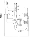
- Figure 1 illustrates hardware of a system according to the present invention.
- Figure 2 is a flow chart illustrating a control routine of a preferred implementation of the present invention.
- FIG. 3 illustrates target A/F input command and system response.
- Figure 4 is a flow chart illustrating a control routine of a second preferred implementation of the present invention.
- Figure 5 illustrates a target A/F input command and A/F sensor output response.
- Figure 6 illustrates another hardware of a system according to the present invention.
- Figure 7 is a flow chart illustrating a control routine of a third preferred implementation of the present invention.
- Figure 8 illustrates preferred relation between holding time of A/F feedback correction efficiency and a period of time during which combustion with lean combustible mixture has continued.
- Figure 9 illustrates target A/F input command and system response.
- Figure 10 illustrates still another hardware of a system according to the present invention.
- Figure 11 is a flow chart illustrating a control routine of a fourth preferred implementation of the present invention.
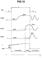
- FIG. 12 illustrates target A/F input command and system response
- Figure 13 illustrates schematically a target A/F command input into a closed fuel control loop of an internal combustion engine having a NOx absorbent catalyst, and NOx emission in the exhaust gas upstream of the catalytic.
- the reference numeral 10 denotes an internal combustion engine, which has an intake passageway 12 including a throttle valve 14.
- the throttle valve 14 meters flow rate of air admitted to cylinders of the engine 10.
- a cylinder draws in air to be mixed with fuel injected by a fuel injector 16 to form a combustible charge.
- the fuel injector 16 may direct a jet of fuel into an intake port of each cylinder or directly into the cylinder.
- a spark produced by a spark plug 18 ignites the combustible charge in the cylinder for combustion.
- Exhaust gas resulting from the combustion is purified by a NOx absorbent catalyst 20 and discharged into the ambient atmosphere.
- the absorbent catalyst 20 which may be named NOx absorbing type three-way catalyst, can absorb NOx within exhaust gas when exhaust A/F is not greater than A/F STOICH (or equal to stoichiometry or rich). With exhaust A/F being greater than A/F STOICH (or lean), it releases the absorbed NOx for reduction process by three-way catalyst layer.
- a controller 22 manages injection timing and duration by the fuel injector 16 and spark timing by the spark plug 18.
- the controller 22 may include a digital microcomputer containing such generally-known components as a central processing unit (CPU), a read only memory (ROM), a random access memory (RAM) and an input/output interface circuit (I/O).
- the controller 22 generates a fuel injection signal (an injection pulse) for fuel injector 16 and a spark signal for spark plug 18 (power transistor).
- the controller 22 determines a target A/F is determined for engine operating conditions and fuel injection quantity (injection pulse width) needed to create combustible charge having the target A/F.
- the controller 22 can set, as the target A/F, a lean A/F
- the controller 22 inputs information of variables representing the engine operating conditions from various sensors.
- the sensors include an airflow meter 24 for detection of intake airflow rate (air quantity), and a throttle sensor 26 for detection of opening degree of the throttle valve 14.
- Exposed to an exhaust passageway 28 are a first and a second A/F sensors 30 and 32.
- the first A/F sensor 30 is disposed upstream of the NOx absorbent catalyst 20 for detection of exhaust A/F.
- the second A/F sensor 32 is disposed downstream of the NOx absorbent catalyst 20 for detection of exhaust A/F.
- the controller 22 inputs information of A/F of the exhaust gas upstream and downstream of the NOx absorbent catalyst 20 from the first and second A/F sensors 30 and 32.
- the controller 22 inputs information of engine speed (RPM) and coolant temperature from a crankshaft angle sensor and a coolant temperature sensor, not shown.
- RPM engine speed
- the first and second A/F sensors 30 and 32 are each a sensor for detection of exhaust A/F based on oxygen concentration within exhaust gas, which sensor may be a stoichometry sensor for detection of the stoichiometry or a wide range A/F sensor for detection of exhaust A/F over a wide range.
- the control scheme performed by the controller 22 may be divided into a first A/F feedback control loop and a second A/F feedback control loop.
- the actual A/F from the first A/F sensor 30 is input to the first A/F feedback control loop.
- the fuel injection quantity is corrected in such a direction as to decrease a deviation of the actual A/F from a target A/F toward zero.
- An A/F feedback correction coefficient ⁇ (alpha) that is used in correcting the fuel injection quantity is set, for example, by proportional integral (PI) control.
- the second A/F feedback control loop come to play a role instead of the first A/F feedback control loop.
- the actual A/F from the second A/F sensor 32 is input into the second A/F feedback control loop.
- the fuel injection quantity is corrected in such a direction as to decrease a deviation of the actual A/F from a target A/F toward zero.
- the flow chart of Figure 2 illustrates a control routine to determine the initiation and termination of the second A/F feedback control loop.
- step 40 the controller 22 determines whether or not a flag FRS is set.
- the controller 22 manages the flag FRS in another control routine, not shown, and sets the flag FRS when predetermined conditions are met.
- the NOx absorbent catalyst 20 absorbs NOx when exhaust A/F is lean, and releases the absorbed NOx when exhaust A/F is stoichiometry or rich. If the target A/F switches the setting from lean to the stoichiometry or rich, the NOx absorbent catalyst 20 releases NOx. Thus, the controller 22 sets the flag FRS under this condition.
- operating conditions which may be represented by operator power demand, engine load, and engine speed, determine when to shift the target A/F from lean to the stoichiometry or rich. If it determines that the NOx absorbed by the absorbent catalyst 20 is about to reach the limit, the controller 22 initiates a temporary enrichment control loop for the release of NOx and purification thereof If this is the case, the controller 22 sets the flag FRS.
- the exhaust A/F downstream of the absorbent catalyst 20 is adjusted towards the stoichiometry or rich setting.
- the controller 22 performs the second A/F feedback control loop until it determines, in step 44, that the second A/F sensor 32 switches the sides from lean to rich. In seep 44, the controller 22 determines whether or not the second A/F sensor 32 has changed from the lean side to the rich side. In this example, the second A/F sensor 32 is of the stoichiometry type. If a so-called wide range A/F sensor is employed as the second A/F sensor 32, the statement of the interrogation in step 44 may read that "Has the predetermined target A/F been reached?"
- step 44 If the interrogation in step 44 results in affirmative, the routine proceeds to step 46 where the controller 22 resets the flag FRS. In the next step 48, the controller 22 switches the inputs from second A/F sensor 32 to first A/F sensor 30.
- Figure 3 illustrates the response of exhaust A/F at the first A/F sensor 30 and exhaust A/F at the second A/F sensor 32 upon and after the controller 22 sets the flag FRS.
- the first A/F sensor 30 switches the sides from lean to rich at relatively early stage. But, the second A/F sensor 32 remains on the lean side upon the switching of the first A/F sensor 30 owing to the separated NOx and O 2 from the NOx absorbent catalyst 20. Thus, the fuel injection quantity continues to increase after the first A/F sensor 30 has switched the sides to rich, creating a so-called "rich spike.” This rich spike shortens time required for the second A/F sensor 32 to switch the sides from lean to rich. Thus, the time required for the exhaust A/F within the NOx absorbent catalyst 20 to switch the sides to rich has been shortened.
- the rich spike has proved to be effective in processing NOx released by the NOx absorbent catalyst 20.
- the rich spike has proved to be effective in processing NOx released by the NOx absorbent catalyst 20.
- the inside of the NOx absorbent catalyst 20 is quickly switched to the rich side, effective reduction of NOx is expected.
- Increase of fuel injection quantity of the rich spike is terminated upon the second A/F sensor 32 switching the sides to rich. This is advantageous in suppressing excessive increase in fuel injection quantity for rich spike even after the NOx absorbing limit and O 2 storage limit drop over extended period of use of the NOx absorbent catalyst 20.
- the controller 22 upon or immediately after the second A/F sensor 32 has switched the sides to rich, the controller 22 renders the first A/F feedback control loop operable and second A/F feedback control loop inoperable. In other words, the controller 22 initiates the A/F feedback control to bring the actual exhaust A/F at the first A/F sensor 30 into agreement with the stoichiometry.
- step 52 the controller 22 switches the inputs from the first A/F sensor 30 to the second A/F sensor 32. Then, the routine proceeds to step 54.
- the timer T ⁇ counts a period of time over which the second A/F feedback control loop, which uses the second A/F sensor 32 as its input, continues to proceed.
- the feedback correction coefficient ⁇ is used as an operation amount for correcting the fuel injection quantity.
- control routine proceeds to step 58.
- step 58 the controller 22 increments the timer T.
- step 60 the controller 22 determines whether T is less than a maximum value T ⁇ max .
- step 60 If, in step 60, T is less than T ⁇ max , the routine proceeds to step 62.
- step 62 the controller 22 increases the correction coefficient ⁇ by an increment N ⁇ . Then, the routine proceeds to step 64.
- step 64 the controller 22 determines whether or not the coefficient ⁇ has exceeded a predetermined maximum value ⁇ max (refer to Figure 5). If this is the case, the routine proceeds to step 66. In step 66, the controller 22 sets the maximum value ⁇ max as the coefficient ⁇ . Owing to proceeding along the steps 64 and 66, excessive increase in fuel injection quantity can be avoided. In other words, occurrence of excessive rich spike is prevented.
- the integral control in steps 62, 64 and 66 may be eliminated.
- the coefficient ⁇ remains at the value that has been set in step 56.
- step 68 the controller 22 determines whether or not the second A/F sensor 32 has switched the sides to rich. If this is the case, the controller 22 determines that rich spike requested has occurred and proceeds to render the first A/F feedback control operable.
- step 70 the controller 22 determines whether or not the timer T ⁇ has exceeded a predetermined minimum value T ⁇ min .
- step 70 the routine proceeds from step 70 to step 72.
- step 72 the controller 22 updates the value resulting from learning LN ⁇ with [(n - 1) x LN ⁇ + ⁇ ']/n , where ⁇ ' is a value of the correction coefficient ⁇ upon the second A/F sensor 32 switching the sides to rich, and n is a predetermined weighing coefficient.
- Updating LN ⁇ in this manner will provide an appropriate value, as a change immediately after the second A/F sensor 32 has replaced the first A/F sensor 30, which is required for causing the second A/F sensor 32 to switch the sides to rich.
- values resulting from learning operation upon switching the sides to rich may be stored against various combinations of values of engine load and values of engine speed.
- step 60 the controller 22 determines that timer T ⁇ has exceeded T ⁇ max .
- the routine proceeds to step 72 for updating LN ⁇ by learning operation.
- ⁇ ' is a value of the correction coefficient ⁇ upon timer T ⁇ having exceeded T ⁇ max .
- step 72 If timer T ⁇ has exceeded T ⁇ max , the routine proceeds to step 72 and then to steps 76, 78 and 80 and the controller 22 renders the first A/F feedback control loop operable without waiting for the second A/F sensor 32 to switch the sides to rich. This is where the second A/F feedback control loop is terminated prior to accomplishing the requested result.
- step 70 the controller 22 determines that timer T ⁇ has failed to exceed T ⁇ min .
- the routine proceeds to step 74.
- step 74 the controller 22 updates the value LN ⁇ with DN ⁇ x LN ⁇ , where DN ⁇ is a coefficient and less than 1 (one). This is where the value LN ⁇ is subjected to decrement. If the period of time required for the second A/F sensor 32 to switch the sides to rich is less than T ⁇ min , the value LN ⁇ is decreased for elongation of the period of time toward T ⁇ min during the subsequent operation cycle. This causes the second A/F sensor 32 to switch the sides to rich with an appropriate response for treatment of NOx.
- step 76 the controller 22 resets the correction coefficient ⁇ equal to the initial value of 100%.
- step 78 the controller 22 resets the flag FRS equal to 0 (zero).
- step 80 the controller 22 switches the inputs from the second A/F sensor 32 to the first A/F sensor 30. Subsequently, the controller 22 continues to perform the first A/F feedback control loop.
- the atmosphere within the NOx absorbent catalyst 20 is quickly adjusted to an appropriate A/F for treatment of NOx, which the catalyst 20 absorbed during the previous lean combustion mode.
- this is not effective in treating NOx that has escaped downstream of the catalyst 20.
- HC and CO owing to enrichment caused by the rich spike during the control scheme need to be treated.
- FIG. 7 shows a portion of a flow chart illustrating a control routine intended also to facilitate treatment of toxic components of exhaust gas by the three-way catalyst 34.
- This flow chart is substantially the same as the flow chart of Figure 4 except the insertion of two steps 82 and 84 downstream of the step 68 and upstream of the step 70 as shown in Figure 7.
- This control routine is substantially the same as the control routine of Figure 4 except as follows.
- the feedback correction coefficient ⁇ established when the second A/F sensor 32 switched the sides to rich is held for a time period, namely, a hold time NRT, that is a function of a time period, namely, a lean combustion time, over which the previous lean combustion mode continued.
- control routine proceeds to step 82 after controller 22 determined, in step 68, that second A/F sensor 32 has switched the side to rich.
- the controller 22 retrieves a table TRNT as illustrated in Figure 8.
- the table TRNT illustrates experimentally determined relation between the hold time NRT and the lean combustion time.
- the controller 22 uses lean combustion time in performing a table look-up operation of the table TRNT to determine a value of NRT.
- the controller 22 holds the correction coefficient ⁇ for time period of NRT. After elapse of the time period of NRT, the routine proceeds to the step 70.
- Figure 9 illustrates clearly that the correction coefficient ⁇ established when the second A/F sensor 32 switched the sides to rich is held for NRT prior to returning to first A/F feedback control loop. This enrichment operation brings about a quick accomplishment of rich A/F within the three-way catalyst 34 for efficient purification of NOx discharged from the absorbent catalyst 20.
- the table TRNT of Figure 8 is referred to determine NRT over which the enrichment operation continues for quick enrichment of exhaust gas within the three-way catalyst 34.
- This open loop enrichment control may be replaced with a closed loop enrichment control as illustrated in Figures 10 to 12.
- Figure 10 illustrates hardware. This hardware is different from that of Figure 6 only the addition of a third A/F sensor 36 downstream of a three-way catalyst 34.
- FIG 11 shows a portion of a flow chart illustrating a control routine intended perform the closed loop enrichment control to facilitate treatment of toxic components of exhaust gas by the three-way catalyst 34.
- This flow chart is substantially the same as the flow chart of Figure 4 except the insertion of two steps 86 and 86 downstream of the step 68 and upstream of the step 70 as shown in Figure 11.
- This control routine is substantially the same as the control routine of Figure 4 except as follows.
- the feedback correction coefficient ⁇ established when the second A/F sensor 32 switched the sides to rich is held until the third A/F sensor 36 switch the sides to rich.
- the control routine proceeds to step 86 after controller 22 determined, in step 68, that second A/F sensor 32 has switched the side to rich.
- the controller 22 holds the correction coefficient ⁇ .
- the controller 22 determines whether or not the third A/F sensor 36 has switched the sides to rich. If this is not the case, the routine returns to step 86. If this is the case, the routine proceeds to the step 70.
- the correction coefficient ⁇ is held until determination in step 88 that the third A/F sensor 36 having switched the sides to rich.
- Figure 12 illustrates clearly that the correction coefficient ⁇ established when the second A/F sensor 32 switched the sides to rich is held until third sensor A/F 36 will switch the sides to rich. This closed loop enrichment operation brings about a quick accomplishment of rich A/F within the three-way catalyst 34 without prolonged rich spike.
Applications Claiming Priority (3)
| Application Number | Priority Date | Filing Date | Title |
|---|---|---|---|
| JP15106597 | 1997-06-09 | ||
| JP151065/97 | 1997-06-09 | ||
| JP15106597A JP3709655B2 (ja) | 1997-06-09 | 1997-06-09 | 内燃機関の排気浄化装置 |
Publications (3)
| Publication Number | Publication Date |
|---|---|
| EP0884458A2 true EP0884458A2 (fr) | 1998-12-16 |
| EP0884458A3 EP0884458A3 (fr) | 2000-06-07 |
| EP0884458B1 EP0884458B1 (fr) | 2003-01-29 |
Family
ID=15510543
Family Applications (1)
| Application Number | Title | Priority Date | Filing Date |
|---|---|---|---|
| EP98110467A Expired - Lifetime EP0884458B1 (fr) | 1997-06-09 | 1998-06-08 | Moteur à combustion interne comprenant un catalyseur absorbant de NOx |
Country Status (5)
| Country | Link |
|---|---|
| US (1) | US6116023A (fr) |
| EP (1) | EP0884458B1 (fr) |
| JP (1) | JP3709655B2 (fr) |
| KR (1) | KR100316501B1 (fr) |
| DE (1) | DE69810998T2 (fr) |
Cited By (4)
| Publication number | Priority date | Publication date | Assignee | Title |
|---|---|---|---|---|
| GB2342465A (en) * | 1998-10-02 | 2000-04-12 | Ford Global Tech Inc | Method of purging a lean NOx trap |
| FR2821390A1 (fr) * | 2001-02-27 | 2002-08-30 | Siemens Ag | Procede de reglage de la concentration d'oxygene d'un systeme catalyseur trifonctionnel |
| EP1284351A2 (fr) * | 2001-08-16 | 2003-02-19 | Dr.Ing. h.c.F. Porsche Aktiengesellschaft | Procede et dispositif de réglage de la composition du mélange d'un moteur à allumage comandé avec un catalyseur a accumulateur de NOx pendant le cycle de régénération |
| EP1134394A3 (fr) * | 2000-03-17 | 2004-12-22 | Ford Global Technologies, Inc. | Méthode de commande du rapport air/carburant d'un moteur à combustion interne à combustion pauvre |
Families Citing this family (19)
| Publication number | Priority date | Publication date | Assignee | Title |
|---|---|---|---|---|
| US6148612A (en) * | 1997-10-13 | 2000-11-21 | Denso Corporation | Engine exhaust gas control system having NOx catalyst |
| DE19827195A1 (de) * | 1998-06-18 | 1999-12-23 | Volkswagen Ag | Verfahren zur De-Sulfatierung eines NOx-Speicherkatalysators |
| US6289672B1 (en) * | 1998-07-21 | 2001-09-18 | Toyota Jidosha Kabushiki Kaisha | Exhaust gas purification device for an internal combustion engine |
| FR2787037B1 (fr) * | 1998-12-09 | 2002-01-11 | Inst Francais Du Petrole | Procede et dispositif d'elimination des oxydes d'azote dans une ligne d'echappement de moteur a combustion interne |
| JP4031887B2 (ja) * | 1999-06-10 | 2008-01-09 | 株式会社日立製作所 | エンジンの空燃比制御装置および方法 |
| DE19936200A1 (de) * | 1999-07-31 | 2001-02-08 | Bosch Gmbh Robert | Verfahren zum Betreiben einer Brennkraftmaschine |
| CA2322915C (fr) * | 1999-10-12 | 2004-12-14 | Honda Giken Kogyo Kabushiki Kaisha | Systeme de controle des gaz d'echappement pour moteur a combustion interne |
| WO2001061174A1 (fr) * | 2000-02-16 | 2001-08-23 | Nissan Motor Co., Ltd. | Dispositif d'epuration des gaz d'echappement d'un moteur |
| US6438944B1 (en) * | 2000-03-17 | 2002-08-27 | Ford Global Technologies, Inc. | Method and apparatus for optimizing purge fuel for purging emissions control device |
| JP2002130019A (ja) * | 2000-10-25 | 2002-05-09 | Honda Motor Co Ltd | リーンNOx触媒に捕捉したNOxを還元するよう空燃比を制御する電子制御装置 |
| JP4003564B2 (ja) | 2002-07-17 | 2007-11-07 | トヨタ自動車株式会社 | 内燃機関の排気浄化装置 |
| JP4304428B2 (ja) * | 2003-02-07 | 2009-07-29 | いすゞ自動車株式会社 | 内燃機関の排気ガス浄化システム |
| ATE465328T1 (de) * | 2004-12-23 | 2010-05-15 | Umicore Ag & Co Kg | Verfahren zur überwachung der stickoxid- speicherfähigkeit eines als startkatalysators eingesetzten stickoxid-speicherkatalysators |
| JP2007247412A (ja) * | 2006-03-13 | 2007-09-27 | Toyota Motor Corp | 内燃機関の空燃比制御装置 |
| JP4548443B2 (ja) * | 2007-04-27 | 2010-09-22 | トヨタ自動車株式会社 | 内燃機関の酸素センサ故障診断装置 |
| KR100907315B1 (ko) * | 2007-12-17 | 2009-07-13 | 한국기계연구원 | 질소산화물의 흡장 탈질 장치 및 질소산화물의 흡장 탈질방법 |
| US8560209B2 (en) | 2010-06-22 | 2013-10-15 | Toyota Motor Engineering & Manufacturing North America, Inc. | Method and system for delivering enrichment to an engine |
| WO2012144269A1 (fr) * | 2011-04-22 | 2012-10-26 | 日産自動車株式会社 | Appareil de régulation de purification de gaz d'échappement de moteur à combustion interne |
| DE102018200440A1 (de) * | 2018-01-12 | 2019-07-18 | Robert Bosch Gmbh | Verfahren zum Steuern eines Dosiersystems mit mehreren Dosierventilen |
Citations (3)
| Publication number | Priority date | Publication date | Assignee | Title |
|---|---|---|---|---|
| EP0581279A2 (fr) * | 1992-07-30 | 1994-02-02 | Toyota Jidosha Kabushiki Kaisha | Dispositif de purification des gaz d'échappement pour moteur à combustion |
| EP0636770A1 (fr) * | 1993-01-19 | 1995-02-01 | Toyota Jidosha Kabushiki Kaisha | Dispositif de nettoyage de gaz d'echappement pour moteur a combustion interne |
| EP0733787A2 (fr) * | 1995-03-24 | 1996-09-25 | Toyota Jidosha Kabushiki Kaisha | Dispositif d'épuration de gaz d'échappement pour moteurs à combustion interne |
Family Cites Families (14)
| Publication number | Priority date | Publication date | Assignee | Title |
|---|---|---|---|---|
| JP2658756B2 (ja) * | 1992-08-11 | 1997-09-30 | トヨタ自動車株式会社 | 内燃機関の排気浄化装置 |
| JP2998481B2 (ja) * | 1993-03-16 | 2000-01-11 | トヨタ自動車株式会社 | 内燃機関の排気浄化装置 |
| JP2743760B2 (ja) * | 1993-03-18 | 1998-04-22 | トヨタ自動車株式会社 | 内燃機関の排気浄化装置 |
| JP2605579B2 (ja) * | 1993-05-31 | 1997-04-30 | トヨタ自動車株式会社 | 内燃機関の排気浄化装置 |
| JP2985638B2 (ja) * | 1993-10-18 | 1999-12-06 | トヨタ自動車株式会社 | 内燃機関の排気浄化装置 |
| JP3144183B2 (ja) * | 1993-11-12 | 2001-03-12 | トヨタ自動車株式会社 | 内燃機関の排気浄化装置 |
| JP3287082B2 (ja) * | 1993-11-15 | 2002-05-27 | トヨタ自動車株式会社 | 内燃機関の排気浄化装置 |
| JPH0886238A (ja) * | 1994-09-16 | 1996-04-02 | Honda Motor Co Ltd | 内燃機関の空燃比制御装置 |
| JP3151368B2 (ja) * | 1995-02-17 | 2001-04-03 | 株式会社日立製作所 | 内燃機関用排気ガス浄化装置の診断装置 |
| JP3237440B2 (ja) * | 1995-02-28 | 2001-12-10 | トヨタ自動車株式会社 | 内燃機関の排気浄化装置 |
| JP2836523B2 (ja) * | 1995-03-24 | 1998-12-14 | トヨタ自動車株式会社 | 内燃機関の排気浄化装置 |
| JP2827954B2 (ja) * | 1995-03-28 | 1998-11-25 | トヨタ自動車株式会社 | NOx 吸収剤の劣化検出装置 |
| JPH09287513A (ja) * | 1996-02-23 | 1997-11-04 | Nissan Motor Co Ltd | エンジンのトルク制御装置 |
| EP0883787A4 (fr) * | 1996-03-01 | 1999-08-04 | Congoleum Corp | Unite de traitement thermique destinee a la preparation de revetements de sol a base de plastisol |
-
1997
- 1997-06-09 JP JP15106597A patent/JP3709655B2/ja not_active Expired - Lifetime
-
1998
- 1998-06-08 DE DE69810998T patent/DE69810998T2/de not_active Expired - Lifetime
- 1998-06-08 EP EP98110467A patent/EP0884458B1/fr not_active Expired - Lifetime
- 1998-06-09 US US09/093,305 patent/US6116023A/en not_active Expired - Lifetime
- 1998-06-09 KR KR1019980021255A patent/KR100316501B1/ko not_active IP Right Cessation
Patent Citations (3)
| Publication number | Priority date | Publication date | Assignee | Title |
|---|---|---|---|---|
| EP0581279A2 (fr) * | 1992-07-30 | 1994-02-02 | Toyota Jidosha Kabushiki Kaisha | Dispositif de purification des gaz d'échappement pour moteur à combustion |
| EP0636770A1 (fr) * | 1993-01-19 | 1995-02-01 | Toyota Jidosha Kabushiki Kaisha | Dispositif de nettoyage de gaz d'echappement pour moteur a combustion interne |
| EP0733787A2 (fr) * | 1995-03-24 | 1996-09-25 | Toyota Jidosha Kabushiki Kaisha | Dispositif d'épuration de gaz d'échappement pour moteurs à combustion interne |
Cited By (8)
| Publication number | Priority date | Publication date | Assignee | Title |
|---|---|---|---|---|
| GB2342465A (en) * | 1998-10-02 | 2000-04-12 | Ford Global Tech Inc | Method of purging a lean NOx trap |
| US6244047B1 (en) | 1998-10-02 | 2001-06-12 | Ford Global Technologies, Inc. | Method of purging lean NOx trap |
| GB2342465B (en) * | 1998-10-02 | 2003-06-18 | Ford Global Tech Inc | Method of purging lean nox trap |
| EP1134394A3 (fr) * | 2000-03-17 | 2004-12-22 | Ford Global Technologies, Inc. | Méthode de commande du rapport air/carburant d'un moteur à combustion interne à combustion pauvre |
| FR2821390A1 (fr) * | 2001-02-27 | 2002-08-30 | Siemens Ag | Procede de reglage de la concentration d'oxygene d'un systeme catalyseur trifonctionnel |
| EP1284351A2 (fr) * | 2001-08-16 | 2003-02-19 | Dr.Ing. h.c.F. Porsche Aktiengesellschaft | Procede et dispositif de réglage de la composition du mélange d'un moteur à allumage comandé avec un catalyseur a accumulateur de NOx pendant le cycle de régénération |
| EP1284351A3 (fr) * | 2001-08-16 | 2004-06-16 | Dr.Ing. h.c.F. Porsche Aktiengesellschaft | Procede et dispositif de réglage de la composition du mélange d'un moteur à allumage comandé avec un catalyseur a accumulateur de NOx pendant le cycle de régénération |
| US6871492B2 (en) * | 2001-08-16 | 2005-03-29 | Dr. Ing. H.C.F. Porsche Ag | Process and system for controlling the mixture composition for a spark ignition Otto engine with an NOx storage catalyst during a regeneration phase |
Also Published As
| Publication number | Publication date |
|---|---|
| EP0884458B1 (fr) | 2003-01-29 |
| DE69810998D1 (de) | 2003-03-06 |
| JPH10339195A (ja) | 1998-12-22 |
| JP3709655B2 (ja) | 2005-10-26 |
| KR19990006798A (ko) | 1999-01-25 |
| DE69810998T2 (de) | 2003-07-17 |
| EP0884458A3 (fr) | 2000-06-07 |
| KR100316501B1 (ko) | 2002-02-19 |
| US6116023A (en) | 2000-09-12 |
Similar Documents
| Publication | Publication Date | Title |
|---|---|---|
| EP0884458A2 (fr) | Moteur à combustion interne comprenant un catalyseur absorbant de NOx | |
| JP3835140B2 (ja) | エンジンの空燃比制御装置 | |
| KR100581642B1 (ko) | 내연기관용 제어장치 | |
| US6978600B2 (en) | Secondary air supply system and secondary air supply method | |
| JPH0494445A (ja) | 内燃機関の蒸発燃料処理制御装置 | |
| JP3932642B2 (ja) | 希薄燃焼内燃機関の排気浄化装置 | |
| JP3344215B2 (ja) | 内燃機関の排気浄化装置 | |
| JP3937487B2 (ja) | 内燃機関の排気浄化装置 | |
| JPH09112308A (ja) | 内燃機関の空燃比制御装置 | |
| JP2000130212A (ja) | 内燃機関の排気浄化装置 | |
| JP2000352338A (ja) | エンジンの空燃比制御装置および方法 | |
| JP2004257270A (ja) | エンジンの空燃比制御方法 | |
| JP3823756B2 (ja) | エンジンの排気浄化装置 | |
| JP3496572B2 (ja) | 内燃機関の排気浄化装置 | |
| EP1469180B1 (fr) | Procédé de contrôle d'un pot catalytique à accumulation de NOx | |
| US20020193934A1 (en) | Closed-loop method and system for purging a vehicle emission control | |
| JPH11247684A (ja) | 内燃機関の燃料噴射制御装置 | |
| JP3892061B2 (ja) | 希薄燃焼機関の空燃比制御装置 | |
| JP2004346844A (ja) | 排気ガス浄化システム | |
| JP4075643B2 (ja) | エンジンの排気浄化装置 | |
| JP3186730B2 (ja) | 内燃機関の排気浄化装置 | |
| JP3512062B2 (ja) | 内燃機関の排気浄化装置 | |
| JP3340051B2 (ja) | 内燃機関の燃料噴射制御装置 | |
| JPH0343640A (ja) | エンジンの燃料制御装置 | |
| JP3632065B2 (ja) | エンジンの排気浄化装置 |
Legal Events
| Date | Code | Title | Description |
|---|---|---|---|
| PUAI | Public reference made under article 153(3) epc to a published international application that has entered the european phase |
Free format text: ORIGINAL CODE: 0009012 |
|
| 17P | Request for examination filed |
Effective date: 19980608 |
|
| AK | Designated contracting states |
Kind code of ref document: A2 Designated state(s): DE FR GB |
|
| AX | Request for extension of the european patent |
Free format text: AL;LT;LV;MK;RO;SI |
|
| PUAL | Search report despatched |
Free format text: ORIGINAL CODE: 0009013 |
|
| AK | Designated contracting states |
Kind code of ref document: A3 Designated state(s): AT BE CH CY DE DK ES FI FR GB GR IE IT LI LU MC NL PT SE |
|
| AX | Request for extension of the european patent |
Free format text: AL;LT;LV;MK;RO;SI |
|
| AKX | Designation fees paid |
Free format text: DE FR GB |
|
| 17Q | First examination report despatched |
Effective date: 20010220 |
|
| GRAG | Despatch of communication of intention to grant |
Free format text: ORIGINAL CODE: EPIDOS AGRA |
|
| GRAG | Despatch of communication of intention to grant |
Free format text: ORIGINAL CODE: EPIDOS AGRA |
|
| GRAH | Despatch of communication of intention to grant a patent |
Free format text: ORIGINAL CODE: EPIDOS IGRA |
|
| GRAH | Despatch of communication of intention to grant a patent |
Free format text: ORIGINAL CODE: EPIDOS IGRA |
|
| GRAA | (expected) grant |
Free format text: ORIGINAL CODE: 0009210 |
|
| AK | Designated contracting states |
Designated state(s): DE FR GB |
|
| REG | Reference to a national code |
Ref country code: GB Ref legal event code: FG4D |
|
| REF | Corresponds to: |
Ref document number: 69810998 Country of ref document: DE Date of ref document: 20030306 Kind code of ref document: P |
|
| ET | Fr: translation filed | ||
| PLBE | No opposition filed within time limit |
Free format text: ORIGINAL CODE: 0009261 |
|
| STAA | Information on the status of an ep patent application or granted ep patent |
Free format text: STATUS: NO OPPOSITION FILED WITHIN TIME LIMIT |
|
| 26N | No opposition filed |
Effective date: 20031030 |
|
| REG | Reference to a national code |
Ref country code: FR Ref legal event code: PLFP Year of fee payment: 19 |
|
| REG | Reference to a national code |
Ref country code: FR Ref legal event code: PLFP Year of fee payment: 20 |
|
| PGFP | Annual fee paid to national office [announced via postgrant information from national office to epo] |
Ref country code: FR Payment date: 20170511 Year of fee payment: 20 Ref country code: GB Payment date: 20170607 Year of fee payment: 20 Ref country code: DE Payment date: 20170530 Year of fee payment: 20 |
|
| REG | Reference to a national code |
Ref country code: DE Ref legal event code: R071 Ref document number: 69810998 Country of ref document: DE |
|
| REG | Reference to a national code |
Ref country code: GB Ref legal event code: PE20 Expiry date: 20180607 |
|
| PG25 | Lapsed in a contracting state [announced via postgrant information from national office to epo] |
Ref country code: GB Free format text: LAPSE BECAUSE OF EXPIRATION OF PROTECTION Effective date: 20180607 |