EP0883093A2 - Lecteur de billets - Google Patents
Lecteur de billets Download PDFInfo
- Publication number
- EP0883093A2 EP0883093A2 EP98113778A EP98113778A EP0883093A2 EP 0883093 A2 EP0883093 A2 EP 0883093A2 EP 98113778 A EP98113778 A EP 98113778A EP 98113778 A EP98113778 A EP 98113778A EP 0883093 A2 EP0883093 A2 EP 0883093A2
- Authority
- EP
- European Patent Office
- Prior art keywords
- banknotes
- banknote
- opening
- banknote reader
- reader according
- Prior art date
- Legal status (The legal status is an assumption and is not a legal conclusion. Google has not performed a legal analysis and makes no representation as to the accuracy of the status listed.)
- Granted
Links
- 238000012423 maintenance Methods 0.000 claims abstract description 17
- 238000009434 installation Methods 0.000 claims description 29
- 238000012360 testing method Methods 0.000 claims description 14
- BASFCYQUMIYNBI-UHFFFAOYSA-N platinum Chemical compound [Pt] BASFCYQUMIYNBI-UHFFFAOYSA-N 0.000 claims 2
- 239000007788 liquid Substances 0.000 claims 1
- 229910052697 platinum Inorganic materials 0.000 claims 1
- 238000013461 design Methods 0.000 description 4
- 230000004888 barrier function Effects 0.000 description 2
- 210000001061 forehead Anatomy 0.000 description 2
- 238000004519 manufacturing process Methods 0.000 description 2
- 238000000034 method Methods 0.000 description 2
- 230000003287 optical effect Effects 0.000 description 2
- 238000011160 research Methods 0.000 description 2
- 101001017827 Mus musculus Leucine-rich repeat flightless-interacting protein 1 Proteins 0.000 description 1
- 230000006978 adaptation Effects 0.000 description 1
- 238000004140 cleaning Methods 0.000 description 1
- 238000010276 construction Methods 0.000 description 1
- 238000005520 cutting process Methods 0.000 description 1
- 230000001419 dependent effect Effects 0.000 description 1
- 238000001514 detection method Methods 0.000 description 1
- 239000000428 dust Substances 0.000 description 1
- 230000002349 favourable effect Effects 0.000 description 1
- 239000011152 fibreglass Substances 0.000 description 1
- 238000003780 insertion Methods 0.000 description 1
- 230000037431 insertion Effects 0.000 description 1
- 230000005285 magnetism related processes and functions Effects 0.000 description 1
- 238000005259 measurement Methods 0.000 description 1
- 230000005226 mechanical processes and functions Effects 0.000 description 1
- 230000009347 mechanical transmission Effects 0.000 description 1
- 239000002184 metal Substances 0.000 description 1
- 238000012544 monitoring process Methods 0.000 description 1
- 238000009420 retrofitting Methods 0.000 description 1
- 230000001960 triggered effect Effects 0.000 description 1
- XLYOFNOQVPJJNP-UHFFFAOYSA-N water Substances O XLYOFNOQVPJJNP-UHFFFAOYSA-N 0.000 description 1
Images


Classifications
-
- G—PHYSICS
- G07—CHECKING-DEVICES
- G07D—HANDLING OF COINS OR VALUABLE PAPERS, e.g. TESTING, SORTING BY DENOMINATIONS, COUNTING, DISPENSING, CHANGING OR DEPOSITING
- G07D7/00—Testing specially adapted to determine the identity or genuineness of valuable papers or for segregating those which are unacceptable, e.g. banknotes that are alien to a currency
- G07D7/06—Testing specially adapted to determine the identity or genuineness of valuable papers or for segregating those which are unacceptable, e.g. banknotes that are alien to a currency using wave or particle radiation
- G07D7/12—Visible light, infrared or ultraviolet radiation
- G07D7/128—Viewing devices
-
- G—PHYSICS
- G07—CHECKING-DEVICES
- G07D—HANDLING OF COINS OR VALUABLE PAPERS, e.g. TESTING, SORTING BY DENOMINATIONS, COUNTING, DISPENSING, CHANGING OR DEPOSITING
- G07D7/00—Testing specially adapted to determine the identity or genuineness of valuable papers or for segregating those which are unacceptable, e.g. banknotes that are alien to a currency
-
- G—PHYSICS
- G07—CHECKING-DEVICES
- G07D—HANDLING OF COINS OR VALUABLE PAPERS, e.g. TESTING, SORTING BY DENOMINATIONS, COUNTING, DISPENSING, CHANGING OR DEPOSITING
- G07D11/00—Devices accepting coins; Devices accepting, dispensing, sorting or counting valuable papers
- G07D11/10—Mechanical details
- G07D11/14—Inlet or outlet ports
-
- G—PHYSICS
- G07—CHECKING-DEVICES
- G07D—HANDLING OF COINS OR VALUABLE PAPERS, e.g. TESTING, SORTING BY DENOMINATIONS, COUNTING, DISPENSING, CHANGING OR DEPOSITING
- G07D11/00—Devices accepting coins; Devices accepting, dispensing, sorting or counting valuable papers
- G07D11/20—Controlling or monitoring the operation of devices; Data handling
- G07D11/22—Means for sensing or detection
-
- G—PHYSICS
- G07—CHECKING-DEVICES
- G07D—HANDLING OF COINS OR VALUABLE PAPERS, e.g. TESTING, SORTING BY DENOMINATIONS, COUNTING, DISPENSING, CHANGING OR DEPOSITING
- G07D11/00—Devices accepting coins; Devices accepting, dispensing, sorting or counting valuable papers
- G07D11/20—Controlling or monitoring the operation of devices; Data handling
- G07D11/26—Servicing, repairing or coping with irregularities, e.g. power failure or vandalism
-
- G—PHYSICS
- G07—CHECKING-DEVICES
- G07D—HANDLING OF COINS OR VALUABLE PAPERS, e.g. TESTING, SORTING BY DENOMINATIONS, COUNTING, DISPENSING, CHANGING OR DEPOSITING
- G07D11/00—Devices accepting coins; Devices accepting, dispensing, sorting or counting valuable papers
- G07D11/40—Device architecture, e.g. modular construction
-
- G—PHYSICS
- G07—CHECKING-DEVICES
- G07F—COIN-FREED OR LIKE APPARATUS
- G07F7/00—Mechanisms actuated by objects other than coins to free or to actuate vending, hiring, coin or paper currency dispensing or refunding apparatus
- G07F7/04—Mechanisms actuated by objects other than coins to free or to actuate vending, hiring, coin or paper currency dispensing or refunding apparatus by paper currency
Definitions
- the invention relates to a banknote reader in Preamble of claim 1 mentioned type.
- banknote readers are suitable, for example, for triggering a service at vending machines using predetermined Denominations of banknotes.
- U.S. Patents 4,807,736 and 4,885,744 describe compact ones Banknote readers for installation in vending machines that work together with a banknote container in the same frame to save space are accommodated.
- test device a buffer for the test device recognized and accepted banknotes. An order can only be triggered with such a banknote reader if the one required for the service, e.g. B. from several Banknotes composed amount already in the cache located.
- CH-PS 661 603 and the patents listed above show the arrangement of test equipment that the banknotes with a scan optical or magnetic methods, as well Facilities for the transportation of banknotes.
- the banknotes are in cash boxes known from CH-PS 658 736, for example stacked, secured against unauthorized theft of banknotes are.
- a stacking device shows the research disclosure, December 1984, RD 24820.
- the invention is based, an inexpensive task To create banknote readers that do not have these disadvantages, but adapt easily to customer-specific needs leaves and is easy to maintain.
- the invention consists in the features specified in claim 1. Advantageous configurations result from the dependent ones Claims.
- 1 means one of the two in a predetermined one Spacing arranged in parallel, essentially rectangular Side boards of a rectangular banknote reader, the Front part 2 easily replaceable on one narrow side of the Side boards 1 is attached.
- the side boards 1 are on the rear narrow side delimited by a border 3 or 3 '.
- the front part 2 has at least one acceptance opening 7 for banknotes 8.
- the border of the section 4 covers a base part 2 'of the front part 2, on which the front part 2 is attached to the side boards 1.
- the banknote reader is for protection against dust and mechanical Damage in a z. B. folded from sheet metal, tubular Inserted sleeve 9 of rectangular cross-section on a first narrow side 9 'between the side boards 1 arranged connection opening 10 releasably to the sleeve 9 connected money container 11 to the banknotes 8 after the Collect acceptance decision in the money container 11.
- the sleeve 9 is dimensioned in length so that the banknote reader of the Base section 2 'up to the edge 3 or 3' within the sleeve 9 is. Under the second narrow side 12, that of the first Opposite the narrow side 9, the side boards 1 have one Cutout for a flap 13.
- the flap 13 is anchored in the side boards 1 Axis pivotally mounted as a hinge 13 '. Once the Is pulled out of the sleeve 9, the flap 13th can be opened and allows free access for maintenance work on the Banknote reader in the interior 14 between the side boards 1. For example, in the drawing of Figure 1, the flap 13 Hinge 13 'in the immediate vicinity of the border 3 on, with the dashed lines the flap 13 at Indicate opening.
- the interior 14 of the banknote reader offers space for one System 15 for the transport of banknotes 8, which is a transport route sets on which the banknotes 8 individually by along the Blocks of the banknote reader arranged for transport be transported.
- the easily replaceable building blocks determine the function of the banknote reader and are fixed Allocated places along the transport route. For example, make up
- the transport system is guided by belts that are not shown here 15, with the axes of the rollers perpendicular to the side boards 1 pierce.
- a switch 19 can be located behind the test device 18 connect that into a return channel 20 through the End wall 2 and branches to a stacker 21.
- the stacker 21 installed in the interior 14, wherein the space for the non-installed blocks 19 and 21 for one any retrofitting remains free.
- the Acceptance opening 7 and the return channel 20 are in cross section narrow rectangles that are perpendicular to the side boards 1 are aligned and their width the dimensions of the largest Denomination corresponds to the banknotes 8 predetermined for acceptance. So that the banknote reader in many countries without major changes can be sold, the distance between the side boards 1 preferably according to the dimensions of the largest banknote, where the country-specific front part 2 according to the nominal values is selected.
- a space that is between the input channel 16 and the Stacker 21 leading to the front part 2 transport route is connected to the transport system 15 Drive unit 22 occupied.
- the transport path is folded. After the tester 18, the transport path bends 180 ° after the first narrow side 9 towards the front part 2 and leads between the tester 18 and the space for the stacker 21 through to the entrance of the switch 19, which is immediately behind the Return channel 20 is located.
- the transport route branches into the switch 19.
- One branch leads to the return channel 20, the other branch bends towards the stacker 21 again after the first Narrow side 9 by 180 ° in the direction of the rear edge 3. He opens into a conveyor belt 23 of the truck 21. All mechanical Functions of the stacker 21 are, for example, of the common drive unit 22 can be driven.
- the conveyor belt 23 extends parallel to the first narrow side 9 of the Turnout 19 to the rear edge 3, so that the transport route Z-folded.
- the stacker 21 points Disclosure, December 1984, RD 24820, a motor driven plunger, which from the conveyor belt 23 to the Connection opening 10 aligned banknotes 8 in the money container 11 promoted.
- the side boards 1 have a greater length, the extended part with the border 3 'in the drawing of the Figure 1 is drawn in dashed lines. It is also conceivable that the Intermediate cash register 24 can also be placed so that the Banknote readers have the advantage of being retrofittable with the Box office 24 has.
- the intermediate checkout 24 takes over from the customer individually through the Acceptance opening 7 entered banknotes 8 at the end of the conveyor belt 23 and places it on a by already entered one Banknotes shaped from bundle.
- the intermediate checkout 24 gives that Bundle on command from a control unit 25 back to the Conveyor belt 23, the bundle as a whole in the reverse direction from the conveyor belt 23 in the direction of Turnout 19 is transported.
- the bundle can from the stacker 21 in the Money container 11 pushed or from the conveyor belt 23 by means of a Guide plate 26 through the return channel 20 to the customer be returned.
- a control unit 25 monitors the functions of the banknote reader, evaluates the measurement results of the test device 18 and adds the service fulfills predetermined sales criteria of the vending machine 6 free.
- the control unit 25 is in the flap 13 installed, which is pivotable with this, so that both the control unit 25 and the Input channel 16 and the tester 18 from the second Narrow side 12 are easily accessible.
- the built-in blocks 16, 18, 19, 21, 22 and 24 are connected to the electronic control unit 25 connected to the necessary Manage data exchange or power supply.
- the Control unit 25 recognizes which of the modules 16, 18, 19, 21, 22 and 24 are connected to it, and is designed to be Program for reading banknotes according to the connected ones Modules 16, 18, 19, 21, 22 and 24 to adapt.
- the banknote reader has the advantage that additional functions are required later according to the additionally installed component executed or locked again without being removed Control unit 25 itself can be replaced or reprogrammed got to.
- the bank note 8 inserted through the acceptance opening 7 is in the Input channel 16 exactly aligned to the transport system 15, that detects the banknote 8 at the input 17 to the test device 18 and forwarded.
- the input channel 16 prevents it from being pushed further banknotes 8 until the checking device 18 for the next one Banknote 8 is free again.
- the checking device 18 scans characteristic features of the banknote 8 with an optical and / or magnetic process.
- the one Control device 25 transmitted measured values or derived therefrom Characteristic values are compared with stored target values. At of a match, the control unit 25 assesses the Banknote 8 as acceptable, the z. B. in the buffer 24th can be stored until the customer decides whether to use the Service desires or not. In the former case, the Buffer 24 stores banknotes 8 in stacker 21, which they with the motor-driven pestle in the money container promoted.
- Buffer 24 transfers the banknotes 8 already entered to the Conveyor belt 23 from which the banknotes 8 through the tree of Stacker 21 conveyed through and the guide plate 26 in the switch 19 returns to the customer through the return channel 20.
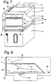
- the banknote reader is 180 ° around its longitudinal axis rotated in the cutout 4 arranged so that the money container 11 is located above the side boards 1 and advantageous new installation options are accessible.
- the stacker 21 is necessary to Banknotes 8 (FIG. 1) upward into the money container 11 Plug.
- the banknote reader for one Installation in this position is the replacement of the front part 2 ( Figure 1) against the front part 27, its acceptance opening 7 and Return channel 20 for more convenient insertion of banknotes 8 are designed differently, whereby from the customer's point of view Acceptance opening 7 is arranged below the return channel 20. Also at the front part 27 are the acceptance opening 7 and the return channel 20 towards the customer too inclined slightly downwards.
- the front parts 2 and the front parts 27 can be made entirely glass fiber reinforced plastic. This technique allowed good ergonomic forms of the acceptance opening 7 and of the return channel 20 inexpensive to manufacture. In the field of Acceptance opening 7 can be plugged into the control unit 25 connected signal display 7 'arranged, for example the Prompts the user to insert further banknotes 8.
- the transport system 15 formed transport route shown as an example in a U-shape. After the test device 18 bends the transport path 180 ° directly to the Stacker 21 and passes the banknote 8 directly to the Conveyor belt 23.
- the shorter transport path has the advantage that the banknote 8 reaches the stacker 21 faster.
- an intermediate checkout 24 (FIG. 1) is present, this includes Transport system 15 according to the tester 18 at the stacker entrance arranged switch 19, one branch of the transport route to Trunk route of the switch leads to in this trunk route at a turn of 180 °.
- the main route of switch 19 forms the conveyor belt 23.
- the switch 19 has pivotably arranged baffle 26, which by means of a Spring 26 'is held in the rest position, the Trunk route of the switch 19 forth the banknotes 8 into a branch 23 ' of the conveyor belt 23 z. B. steerable to the checkout 24 ( Figure 1) because the branch to the transport route is covered.
- Passive control of the switch 19 has the advantage the simplicity and a relief of the power supply and the Control unit 25 ( Figure 1), since only by reversing the Drive unit 22 ( Figure 1), i. H. by changing the transport direction, the transport route in the switch 19 is determined.
- the banknote reader has the advantage that after the simple Replacing the front part 2 against the front part 27 of the Application area of the banknote reader is expanded and that both simple and comfortable designs with the same building blocks can be manufactured and the simple ones Executions at any time, even under difficult conditions in the field can be retrofitted.
- the blocks with the same functions can be different Executions, wherein they meet the requirement regarding Space requirements and the transport route of the banknotes 8 meet have to.
- the test device 18 is an example at this point mentioned that, depending on the design, optically and / or magnetically Features of banknote 8 scans.
- the money container 11 has a lever 28 which is on a Slider to open and close its inlet opening works.
- An advantageously arranged on the money container 11 mechanical sensor 29 is for sensing the relative position of the Cash container 11 to the sleeve 9 or to the connection opening 10 set up.
- the sensor 29 prevents the cash container from opening 11 as long as the sensor 29 is not predetermined in the Sleeve 9 is engaged. Conversely, the money container 11 cannot be removed from the sleeve 9 when the connection opening 10 is still open and the sensor 29 is engaged. This increases the Security against unauthorized manipulation by unauthorized persons.
- the simplest version of the banknote reader described above without switch 19, stacker 21 and cash register 24 has one Transport path according to Figure 2 and is only in the installed position usable according to FIG. 1.
- the control unit 25 Accepted banknotes 8 are from the transport system 15 to the connection opening 10 out and fall loosely into the money container 11, which is an open container, for example a simple sack that can be. Unapproved banknotes will be 8 returned by the transport system 15.
- the banknote 8 is reversed by the transport system 15 the direction of transport again through the acceptance opening 7 User returned as soon as the controller 25 for the Return has decided.
- the control unit 25 is advantageous for Detection of a coding in connection with the plug contact of the Signal display 7 'set up, for. B. by means of a short circuit bridge in the connector part.
- the control unit 25 reads the connector coding and is informed about the existence of the Return channel 20 so that the program of the control unit 25th adapts to the design of the banknote reader.
- banknote 8 To also secure the banknotes 8 with different widths To be able to recognize the banknotes 8 in the checking device 18 Align reading and recognizing. For this purpose, banknote 8 enter left-aligned into the acceptance opening 7 because this orientation is easiest for the customer. This requires however, an asymmetrical arrangement of the modules in the scaffolding the banknote reader and the inlet opening of the money container 11, to securely stack even narrow banknotes 8.
- the asymmetrical The arrangement requires a perpendicular to the side boards 1 Slidable arrangement of the building blocks to in all installation positions the banknote reader to the left-aligned input of banknotes 8 guarantee. Control over the predetermined location of the Banknote 8 can be in the acceptance opening 7 of the forehead or Front parts 2 and 27 take place.
- the locking of the sensor 29 is on one of the two permissible versions A and B of the Vote container 11.
- FIGS. 3 and 4 show four possible combinations of Arrangement of the banknote reader and the money container 11 as they can be used for installation in the vending machine 6 ( Figure 1).
- the money container 11A is for the arrangement according to FIGS. 3a and 4b provided, while in Figures 3b and 4a the for Version A serves as a mirror image of the money container 11B is.
- the money container 11A is below the sleeve 9 arranged.
- the banknote reader is with the front part 2 equipped.
- the cash box 11A is replaceable cuboid cassette formed, the inlet opening on the Connection opening 10 ( Figure 1) aligned and when actuated the lever 28 can be closed by means of closing plates.
- the sleeve 9 is towards the money container 11 extended on both sides with profiles, so that when Insert the money container 11, the two grooves 30 in the Intervene profiles.
- the banknote reader and the money container 11 together form an installation unit 32.
- the money container 11 in The Swiss mentioned at the beginning shows a massive version Patent No. 658 736.
- the cash container 11 has a handle 31 on its front side and the lever 28.
- the handle 31 On the handle 31 is the money container 11, the with the grooves 30 slides in the profiles of the sleeve 9, convenient so far insertable until the sensor 29 ( Figure 2) in the predetermined position of the money container 11 engages and the Lever 28 for opening the inlet opening of the cash container 11 releases so that the installation unit 32 is ready for operation.
- the banknote reader is an advantage for easy maintenance within the sleeve 9 on at least one telescopic rail 33 arranged.
- the telescopic rails 33 are in this way on the side boards 1 ( Figure 1) attached that the flap 13 ( Figure 1) is concealed laterally, but outside the envelope 9 is freely pivotable.
- the banknote reader is therefore slightly out of the sleeve 9 with the front part 2 in the direction an arrow 34 can be pulled out for maintenance when the wall 5 ( Figure 1) of the vending machine 6 is removed. In its predetermined working position is by means of a second rotary lock lockable with the key of the bakknot reader.
- the installation unit 32 can be installed 3b may be required.
- the installation unit 32 is 180 ° about an axis perpendicular to the face 2 opposite the Arrangement rotated in Figure 3a and the front part 2 (Figure 3a) replaced with the ergonomically more favorable front part 27; this requires the use of the 11B cash container.
- FIG. 5 shows the vending machine 6 with the in the Operating position arranged installation unit 32, the for example in a building wall 36 in a niche 37 is installed.
- the niche 37 can be pulled out or the money container 11 interchangeable.
- the Money container 11B or 11A and the banknote reader opposed oriented to each other that is, the lever 28 ( Figure 3a) and the Front or front part 2 or 27 are on the two each other opposite sides of the installation unit 32 are arranged.
- the 11B and 11A version of the money container is from the wall 5 ( Figure 1) facing away from the installation unit 32 ago operable and the banknote reader is opposite to the direction of arrow 34 extendable from the sleeve 9.
- the handle 31 (FIG. 3a) and the lever 28 (FIG. 3a) are not visible, as this on the front or front part 2 or 27 facing away from the installation unit 32 are arranged.
- FIG. 6a and 6b show the installation of the banknote reader in a security room 38 is shown, the one being the return / acceptance part trained end or front part 2 or 27 ( Figure 4b) and the wall 5 together with the building wall 36 the security room 38 demarcate from the audience.
- Both the money container 11 is interchangeable and the necessary maintenance can be carried out.
- the installation unit 32 is with Advantage arranged on roller bearings 39, 39 ', so that the installation unit 32 for maintenance without additional help from one Installer can be moved into the security room 38.
- the installation unit 32 can extend as far into the Security room 38 that the cash container 11 is pulled through the section 4 is no longer accessible through; this prevents an unauthorized person from cutting out 4 through to create money container 11. After completion the maintenance work is the installation unit 32 with little effort can be pushed back onto the wall 5 (FIG. 6a).
- the U-shaped transport path ( Figure 2) has another advantage easier accessibility.
- the example is Installation unit in the arrangement according to FIG. 3a in FIG. 7 shown, the two side boards 1 of the scaffolding along a substantially diagonal dividing line 40 into one Upper part 41 and a lower part 42 are divided.
- the two parts of the scaffolding are together by means of a common Axis 43 at the level of the return channel 20 on the front or Front part 2 or 27 ( Figure 2) opposite side articulated connected.
- the front or front part 2 or 27 is on the Lower part 42 arranged with a U-shaped Intermediate piece 44 for the connection to the money container 11 is equipped.
- the U-shaped intermediate piece 44 engages in the Grooves 30 of the cash box.
- the two side boards 1 of the Lower part 42 can advantageously each have three pins 45 in an identical manner
- Have arrangement with which the banknote reader in each Installation position is arranged on a mounting plate 46, wherein the space 35 between the side board 1 and the Mounting plate 46 remains free.
- Upper part 41 and the lower part 42 locked together.
- the Mounting plate 46 can be directly or through the Telescopic rail 33 ( Figure 6b) connected to the vending machine be.
- the hood 1 (FIG. 1) can also be omitted.
- the flap 13 with the control device 25 ( Figure 1) is advantageous with the hinge 13 'on the upper edge of one side board 1 of the upper part 41 articulated so that connector 47 for the signal and Supply lines can be led away to the rear and without interrupting this, the flap 13 around the hinge 13 ' remains easily pivotable. Unfolding the upper part 41 and / or pivoting of the flap 1 is therefore also in the Installation position possible.
- the Transport route in the area of the input channel 16 ( Figure 1) and the Tester 18 ( Figure 1) to be completely exposed, especially To maintain or adjust sensors of the test device 18.
- the banknotes 8 are shown schematically in FIG drawn, U-shaped transport path through the acceptance opening 7 entered in the front part 2, the banknote 8 in the direction of Arrows 48 is transported.
- the banknote reader is a instead of the stacker 21 ( Figure 2) the switch 19 ( Figure 1) controlled by the tester 18 ( Figure 1) Deflector 49 arranged.
- the deflector 49 can be in the transport route be pivoted in so that the banknote 8 ( Figure 1) deflected from the transport route into the money container 11 and falls into it. Is the acceptance of banknote 8 too refuse, the deflector 49 has pivoted out of the transport route, so that the banknote 8 is returned via the return channel 20 becomes.
Landscapes
- Physics & Mathematics (AREA)
- General Physics & Mathematics (AREA)
- Health & Medical Sciences (AREA)
- General Health & Medical Sciences (AREA)
- Toxicology (AREA)
- Control Of Vending Devices And Auxiliary Devices For Vending Devices (AREA)
- Financial Or Insurance-Related Operations Such As Payment And Settlement (AREA)
- Inspection Of Paper Currency And Valuable Securities (AREA)
Applications Claiming Priority (4)
| Application Number | Priority Date | Filing Date | Title |
|---|---|---|---|
| CH1271/92 | 1992-04-16 | ||
| CH127192 | 1992-04-16 | ||
| CH127192 | 1992-04-16 | ||
| EP93907739A EP0591485B1 (fr) | 1992-04-16 | 1993-04-14 | Lecteur optique de billets de banque |
Related Parent Applications (1)
| Application Number | Title | Priority Date | Filing Date |
|---|---|---|---|
| EP93907739.2 Division | 1993-11-11 |
Publications (3)
| Publication Number | Publication Date |
|---|---|
| EP0883093A2 true EP0883093A2 (fr) | 1998-12-09 |
| EP0883093A3 EP0883093A3 (fr) | 1999-07-14 |
| EP0883093B1 EP0883093B1 (fr) | 2005-11-02 |
Family
ID=4206506
Family Applications (2)
| Application Number | Title | Priority Date | Filing Date |
|---|---|---|---|
| EP93907739A Expired - Lifetime EP0591485B1 (fr) | 1992-04-16 | 1993-04-14 | Lecteur optique de billets de banque |
| EP98113778A Revoked EP0883093B1 (fr) | 1992-04-16 | 1993-04-14 | Lecteur de billets |
Family Applications Before (1)
| Application Number | Title | Priority Date | Filing Date |
|---|---|---|---|
| EP93907739A Expired - Lifetime EP0591485B1 (fr) | 1992-04-16 | 1993-04-14 | Lecteur optique de billets de banque |
Country Status (8)
| Country | Link |
|---|---|
| US (1) | US5909792A (fr) |
| EP (2) | EP0591485B1 (fr) |
| JP (1) | JP3710137B2 (fr) |
| KR (1) | KR940701570A (fr) |
| CA (1) | CA2111585A1 (fr) |
| DE (2) | DE59309650D1 (fr) |
| ES (2) | ES2248864T3 (fr) |
| WO (1) | WO1993021609A1 (fr) |
Cited By (4)
| Publication number | Priority date | Publication date | Assignee | Title |
|---|---|---|---|---|
| DE10012367A1 (de) * | 2000-03-14 | 2001-09-27 | Leicher Gmbh & Co | Banknotenverarbeitungsmaschine |
| WO2003012747A2 (fr) * | 2001-07-30 | 2003-02-13 | Innovative Technology Limited | Manutention de billets de banque et analogues |
| DE10336389A1 (de) * | 2003-08-06 | 2005-03-17 | Wincor Nixdorf International Gmbh | Selbstbedienungsgerät mit Überwachungsvorrichtung |
| EP2012279A2 (fr) | 2007-06-26 | 2009-01-07 | Innovative Technology Limited | Validateur de billet de banque et/ou carte et appareil de stockage |
Families Citing this family (25)
| Publication number | Priority date | Publication date | Assignee | Title |
|---|---|---|---|---|
| US5735516A (en) * | 1992-05-27 | 1998-04-07 | Mars Incorporated | Apparatus for handling sheets |
| US6736251B2 (en) | 1992-09-04 | 2004-05-18 | Coinstar, Inc. | Coin counter and voucher dispensing machine and method |
| US7028827B1 (en) | 1992-09-04 | 2006-04-18 | Coinstar, Inc. | Coin counter/sorter and coupon/voucher dispensing machine and method |
| US5544728A (en) * | 1994-05-24 | 1996-08-13 | Dabrowski; Stanley P. | Retrofit bill validator assembly |
| US6047886A (en) * | 1998-01-06 | 2000-04-11 | Cash Code Company Inc. | Validator with replaceable sensor module |
| US7430520B1 (en) * | 2000-08-11 | 2008-09-30 | Affinion Net Patents, Inc. | System and method for determining the level of a authentication required for redeeming a customer's award credits |
| US6602125B2 (en) | 2001-05-04 | 2003-08-05 | Coinstar, Inc. | Automatic coin input tray for a self-service coin-counting machine |
| US7865432B2 (en) | 2002-02-15 | 2011-01-04 | Coinstar, Inc. | Methods and systems for exchanging and/or transferring various forms of value |
| WO2003071495A1 (fr) | 2002-02-15 | 2003-08-28 | Coinstar, Inc. | Procedes et systemes d'echange et/ou de transfert de divers types de moyens de paiement |
| US8033375B2 (en) | 2002-02-15 | 2011-10-11 | Coinstar, Inc. | Methods and systems for exchanging and/or transferring various forms of value |
| US20060113162A1 (en) * | 2004-11-29 | 2006-06-01 | Kenneth Ottesen | Validator guide |
| DE102006028632A1 (de) | 2006-06-22 | 2007-12-27 | Giesecke & Devrient Gmbh | Bearbeitungsvorrichtung für Wertdokumente |
| DE102008038801A1 (de) * | 2008-08-13 | 2010-02-18 | Wincor Nixdorf International Gmbh | Rollenspeicheranordnung |
| WO2010032281A1 (fr) * | 2008-09-22 | 2010-03-25 | 富士通フロンテック株式会社 | Unité de traitement d’acceptation de billets de banque et unité d'insertion/de retour pouvant être annexée à l’unité de traitement d'acceptation de billets de banque et désannexée de celle-ci |
| JP5434538B2 (ja) * | 2009-12-03 | 2014-03-05 | 沖電気工業株式会社 | 媒体処理装置 |
| AU2011323490A1 (en) | 2010-11-01 | 2013-05-02 | Outerwall Inc. | Gift card exchange kiosks and associated methods of use |
| US8874467B2 (en) | 2011-11-23 | 2014-10-28 | Outerwall Inc | Mobile commerce platforms and associated systems and methods for converting consumer coins, cash, and/or other forms of value for use with same |
| US9129294B2 (en) | 2012-02-06 | 2015-09-08 | Outerwall Inc. | Coin counting machines having coupon capabilities, loyalty program capabilities, advertising capabilities, and the like |
| US9036890B2 (en) | 2012-06-05 | 2015-05-19 | Outerwall Inc. | Optical coin discrimination systems and methods for use with consumer-operated kiosks and the like |
| US8967361B2 (en) | 2013-02-27 | 2015-03-03 | Outerwall Inc. | Coin counting and sorting machines |
| US9022841B2 (en) | 2013-05-08 | 2015-05-05 | Outerwall Inc. | Coin counting and/or sorting machines and associated systems and methods |
| US9443367B2 (en) | 2014-01-17 | 2016-09-13 | Outerwall Inc. | Digital image coin discrimination for use with consumer-operated kiosks and the like |
| US9235945B2 (en) | 2014-02-10 | 2016-01-12 | Outerwall Inc. | Coin input apparatuses and associated methods and systems |
| US10346819B2 (en) | 2015-11-19 | 2019-07-09 | Coinstar Asset Holdings, Llc | Mobile device applications, other applications and associated kiosk-based systems and methods for facilitating coin saving |
| GB2570706B (en) * | 2018-02-05 | 2020-10-14 | Innovative Tech Ltd | A banknote validator |
Citations (7)
| Publication number | Priority date | Publication date | Assignee | Title |
|---|---|---|---|---|
| DE2028649A1 (de) | 1969-06-11 | 1971-12-02 | Safaa | Automatisches Gerät zum vorübergehenden Einspeichern von Blättern oder Karten, insbesondere Banknoten |
| DE2619620A1 (de) | 1975-07-24 | 1977-01-27 | Landis & Gyr Gmbh | Speichereinrichtung fuer kurzzeitiges speichern von papierblaettern, insbesondere banknoten |
| FR2453811A1 (fr) | 1979-04-12 | 1980-11-07 | Crouzet Sa | Accepteur de billets de banque |
| CH658736A5 (de) | 1983-02-11 | 1986-11-28 | Sodeco Compteurs De Geneve | Banknotenkassette. |
| CH661603A5 (en) | 1985-01-11 | 1987-07-31 | Sodeco Compteurs De Geneve | Apparatus for authenticating and identifying valuable documents, especially bank notes |
| US4807736A (en) | 1986-01-07 | 1989-02-28 | I.M. Electronics Co., Ltd. | Apparatus for discriminating paper moneys and stacking the same |
| US4858744A (en) | 1988-02-16 | 1989-08-22 | Ardac, Inc. | Currency validator |
Family Cites Families (57)
| Publication number | Priority date | Publication date | Assignee | Title |
|---|---|---|---|---|
| US3026023A (en) * | 1962-03-20 | Bank for paper money | ||
| US3064785A (en) * | 1962-11-20 | weingart | ||
| US2278188A (en) * | 1940-08-03 | 1942-03-31 | Interchem Corp | Method of and apparatus for delivering sheets |
| US3108694A (en) * | 1959-09-14 | 1963-10-29 | Gen Electric | System for collating documents in response to indicia apparing thereon |
| US3083012A (en) * | 1960-06-29 | 1963-03-26 | Sperry Rand Corp | Delay device for document feeding apparatus |
| FR1271264A (fr) * | 1960-07-30 | 1961-09-08 | Cie Crouzet | Mécanisme d'entraînement en pas à pas verrouillable à plusieurs vitesses |
| US3222057A (en) * | 1961-11-29 | 1965-12-07 | Joseph M Couri | Apparatus and method for controlling and receiving and/or dispensing paper money |
| CH407178A (de) * | 1961-12-23 | 1966-02-15 | Hepp Rudolf | Verfahren zum Auseinanderspreizen gefalzter Bogen |
| US3162439A (en) * | 1962-09-24 | 1964-12-22 | Sperry Rand Corp | Document stacking device |
| US3272044A (en) * | 1962-10-09 | 1966-09-13 | West Virginia Pulp & Paper Co | Single web sheet cutting mechanism |
| US3265205A (en) * | 1963-09-05 | 1966-08-09 | Nat Rejectors Gmbh | Paper currency detector having magnetic and optical sensing means |
| US3426879A (en) * | 1967-05-19 | 1969-02-11 | Docutel Inc | Counterfeit document security system |
| US3481464A (en) * | 1967-08-03 | 1969-12-02 | Francis E Townsend | Bill validating apparatus |
| US3447655A (en) * | 1967-09-22 | 1969-06-03 | Micro Magnetic Ind Inc | Bill validator with escrow device |
| NL6812166A (fr) * | 1968-08-27 | 1970-03-03 | ||
| US3614087A (en) * | 1969-10-22 | 1971-10-19 | Zerand Corp | Carton blank handling apparatus |
| DE2064724A1 (de) * | 1970-12-31 | 1972-07-20 | Brockfeld & Meyer, 4981 Spradow | Vorrichtung zum Sortieren und Stapeln von Tabakblättern unterschiedlicher Länge |
| DE2157379A1 (de) * | 1971-11-19 | 1973-05-24 | Guenter Twiefel | Einrichtung zum stapeln von losen papierbogen |
| CH558575A (de) * | 1973-05-24 | 1975-01-31 | Sodeco Compteurs De Geneve | Speichereinrichtung fuer kurzzeitiges speichern von papierblaettern, insbesondere von banknoten. |
| JPS5026600A (fr) * | 1973-07-05 | 1975-03-19 | ||
| US3917260A (en) * | 1973-12-06 | 1975-11-04 | Rowe International Inc | Bill stacking mechanism |
| DE2408584A1 (de) * | 1974-02-22 | 1975-08-28 | Licentia Gmbh | Einrichtung in fahrkartenautomaten |
| DE2760165C2 (fr) * | 1977-07-01 | 1988-06-01 | Gao Gesellschaft Fuer Automation Und Organisation Mbh, 8000 Muenchen, De | |
| US4168058A (en) * | 1977-11-30 | 1979-09-18 | Ncr Corporation | Record member feeding device |
| US4193685A (en) * | 1979-03-30 | 1980-03-18 | Terminal Data Corporation | Fixed message carrier |
| DE2926387C2 (de) * | 1979-06-29 | 1981-10-01 | Windmöller & Hölscher, 4540 Lengerich | Sammelzylinder zum Bilden von Stapeln aus flachen Werkstücken |
| GB2059391B (en) * | 1979-09-25 | 1983-06-22 | Laurel Bank Machine Co | Stacking paper sheets bank notes in dispensers |
| US4585144A (en) * | 1980-06-26 | 1986-04-29 | Ncr Corporation | Record member dispensing system |
| US4479049A (en) * | 1981-01-22 | 1984-10-23 | Tokyo Shibaura Denki Kabushiki Kaisha | Automatic bank note transaction apparatus |
| JPS5836852A (ja) * | 1981-08-24 | 1983-03-03 | Nippon Coinco:Kk | 紙幣の保留装置 |
| DE3173634D1 (en) * | 1981-09-18 | 1986-03-13 | Goebel Gmbh Maschf | Mechanism for driving a sheet delivering device |
| NL8104325A (nl) * | 1981-09-21 | 1983-04-18 | Estel Hoogovens Bv | Inrichting voor het geleiden van een sublans. |
| US4482057A (en) * | 1981-12-30 | 1984-11-13 | Ncr Corporation | Record media dispensing apparatus |
| JPS5916094A (ja) * | 1982-07-20 | 1984-01-27 | 株式会社日本コンラックス | 紙幣受入装置 |
| US4462509A (en) * | 1982-12-09 | 1984-07-31 | Ncr Corporation | Currency stacker and presenter |
| FR2545462B1 (fr) * | 1983-05-02 | 1986-02-07 | Crouzet Sa | Dispositif d'entrainement de bobines |
| JPS59205693A (ja) * | 1983-05-06 | 1984-11-21 | オムロン株式会社 | 紙幣処理装置 |
| JPS59223650A (ja) * | 1983-05-31 | 1984-12-15 | Toshiba Corp | 紙葉類の集積装置 |
| IT1162910B (it) * | 1983-07-15 | 1987-04-01 | Urmet Spa Costruzioni Elettrot | Dispositivo di lettura e obliterazione di schede valorizzate particolarmente schede magnetiche per l'abilitazione di apparecchi telefonici pubblici |
| US4557352A (en) * | 1983-11-07 | 1985-12-10 | United Banks Of Colorado, Inc. | Apparatus and method for drive-up banking |
| US4578009A (en) * | 1984-03-28 | 1986-03-25 | Ncr Corporation | Collector and carriage mechanism for use in a sheet dispenser |
| US4552350A (en) * | 1984-03-28 | 1985-11-12 | Ncr Corporation | Transport for diverted and purged sheets in a sheet dispenser |
| JPS6149736U (fr) * | 1984-09-03 | 1986-04-03 | ||
| US4624359A (en) * | 1984-12-20 | 1986-11-25 | Ncr Corporation | Flexible drive system |
| GB8505759D0 (en) * | 1985-03-06 | 1985-04-11 | De La Rue Syst | Assembling sheets into stack |
| US4871085A (en) * | 1985-06-27 | 1989-10-03 | Diebold Incorporated | Apparatus for identifying and indicating the content of document canisters |
| KR910009308B1 (ko) * | 1986-03-18 | 1991-11-09 | 가부시기가이샤 닛본곤락스 | 지폐장치 |
| GB2193488B (en) * | 1986-08-05 | 1989-12-20 | Ncr Co | Sheet feeding apparatus |
| JPH0766460B2 (ja) * | 1986-10-30 | 1995-07-19 | ロ−レルバンクマシン株式会社 | 紙幣入出金機 |
| GB2197279B (en) * | 1986-11-06 | 1990-01-17 | Ncr Co | Sheet feeding apparatus |
| GB2209518B (en) * | 1987-09-10 | 1991-09-04 | Ncr Co | Sheet handling apparatus. |
| JPH0721832B2 (ja) * | 1987-11-20 | 1995-03-08 | インタ−ナシヨナル・ビジネス・マシ−ンズ・コ−ポレ−シヨン | 紙幣処理装置 |
| CH690471A5 (de) * | 1988-04-18 | 2000-09-15 | Mars Inc | Einrichtung zum Erkennen der Echtheit von Dokumenten. |
| DE3914178A1 (de) * | 1989-04-28 | 1990-10-31 | Nixdorf Computer Ag | Verfahren zum uebernehmen und zum weitergeben von blattmaterial an eine ausgabestation sowie einrichtung zur durchfuehrung dieses verfahrens |
| SE463283B (sv) * | 1989-07-20 | 1990-10-29 | Inter Innovation Ab | Anordning foer inmatning av vaerdepapper, saasom sedlar, checker etc |
| US5222584A (en) * | 1991-04-18 | 1993-06-29 | Mars Incorporated | Currency validator |
| US5156250A (en) * | 1991-09-26 | 1992-10-20 | Mid-South Enterprises | Liquid diverter for currency receiver |
-
1993
- 1993-04-14 JP JP51781593A patent/JP3710137B2/ja not_active Expired - Fee Related
- 1993-04-14 ES ES98113778T patent/ES2248864T3/es not_active Expired - Lifetime
- 1993-04-14 WO PCT/CH1993/000095 patent/WO1993021609A1/fr active IP Right Grant
- 1993-04-14 DE DE59309650T patent/DE59309650D1/de not_active Expired - Lifetime
- 1993-04-14 EP EP93907739A patent/EP0591485B1/fr not_active Expired - Lifetime
- 1993-04-14 KR KR1019930703896A patent/KR940701570A/ko not_active Application Discontinuation
- 1993-04-14 DE DE59310381T patent/DE59310381D1/de not_active Revoked
- 1993-04-14 EP EP98113778A patent/EP0883093B1/fr not_active Revoked
- 1993-04-14 ES ES93907739T patent/ES2132226T3/es not_active Expired - Lifetime
- 1993-04-14 CA CA002111585A patent/CA2111585A1/fr not_active Abandoned
-
1997
- 1997-07-10 US US08/891,147 patent/US5909792A/en not_active Expired - Fee Related
Patent Citations (7)
| Publication number | Priority date | Publication date | Assignee | Title |
|---|---|---|---|---|
| DE2028649A1 (de) | 1969-06-11 | 1971-12-02 | Safaa | Automatisches Gerät zum vorübergehenden Einspeichern von Blättern oder Karten, insbesondere Banknoten |
| DE2619620A1 (de) | 1975-07-24 | 1977-01-27 | Landis & Gyr Gmbh | Speichereinrichtung fuer kurzzeitiges speichern von papierblaettern, insbesondere banknoten |
| FR2453811A1 (fr) | 1979-04-12 | 1980-11-07 | Crouzet Sa | Accepteur de billets de banque |
| CH658736A5 (de) | 1983-02-11 | 1986-11-28 | Sodeco Compteurs De Geneve | Banknotenkassette. |
| CH661603A5 (en) | 1985-01-11 | 1987-07-31 | Sodeco Compteurs De Geneve | Apparatus for authenticating and identifying valuable documents, especially bank notes |
| US4807736A (en) | 1986-01-07 | 1989-02-28 | I.M. Electronics Co., Ltd. | Apparatus for discriminating paper moneys and stacking the same |
| US4858744A (en) | 1988-02-16 | 1989-08-22 | Ardac, Inc. | Currency validator |
Cited By (7)
| Publication number | Priority date | Publication date | Assignee | Title |
|---|---|---|---|---|
| DE10012367A1 (de) * | 2000-03-14 | 2001-09-27 | Leicher Gmbh & Co | Banknotenverarbeitungsmaschine |
| WO2003012747A2 (fr) * | 2001-07-30 | 2003-02-13 | Innovative Technology Limited | Manutention de billets de banque et analogues |
| WO2003012747A3 (fr) * | 2001-07-30 | 2003-10-16 | Innovative Technology Ltd | Manutention de billets de banque et analogues |
| DE10336389A1 (de) * | 2003-08-06 | 2005-03-17 | Wincor Nixdorf International Gmbh | Selbstbedienungsgerät mit Überwachungsvorrichtung |
| EP2012279A2 (fr) | 2007-06-26 | 2009-01-07 | Innovative Technology Limited | Validateur de billet de banque et/ou carte et appareil de stockage |
| EP2012279A3 (fr) * | 2007-06-26 | 2010-11-03 | Innovative Technology Limited | Validateur de billet de banque et/ou carte et appareil de stockage |
| EP2602772A3 (fr) * | 2007-06-26 | 2013-12-25 | Innovative Technology Limited | Validateur de billet de banque et/ou carte et appareil de stockage |
Also Published As
| Publication number | Publication date |
|---|---|
| EP0591485B1 (fr) | 1999-06-16 |
| JP3710137B2 (ja) | 2005-10-26 |
| EP0883093B1 (fr) | 2005-11-02 |
| EP0883093A3 (fr) | 1999-07-14 |
| KR940701570A (ko) | 1994-05-28 |
| US5909792A (en) | 1999-06-08 |
| WO1993021609A1 (fr) | 1993-10-28 |
| CA2111585A1 (fr) | 1993-10-28 |
| ES2248864T3 (es) | 2006-03-16 |
| DE59310381D1 (de) | 2005-12-08 |
| EP0591485A1 (fr) | 1994-04-13 |
| ES2132226T3 (es) | 1999-08-16 |
| JPH07500204A (ja) | 1995-01-05 |
| DE59309650D1 (de) | 1999-07-22 |
Similar Documents
| Publication | Publication Date | Title |
|---|---|---|
| EP0591485B1 (fr) | Lecteur optique de billets de banque | |
| DE4434126C1 (de) | Vorrichtung zur Entnahme eines Banknotenbehälters, der einer Banknotenprüfeinrichtung in einem münzbetätigten Unterhaltungsautomaten zugeordnet ist | |
| DE60130861T2 (de) | Geldscheinverarbeitungsgerät | |
| DE2437994C3 (de) | Gerät zum Deponieren von Einlagen, wie Geldscheinen, Schecks o.dgl | |
| DE3635965A1 (de) | Selbstbedienungsbanksystem | |
| DE69725011T2 (de) | Sicherheitsberechtigungsschein für elektronische sperrvorrichtung in verkaufsautomaten | |
| DE3127167C2 (de) | Einrichtung zum Ausscheiden von Banknoten für einen automatischen Geldausgabe-Bankschalter | |
| DE3513635C2 (fr) | ||
| DE60025252T2 (de) | Apparat zum verarbeiten von banknoten | |
| WO2007147607A2 (fr) | Système de traitement de documents de valeur | |
| DE3806723C2 (de) | Zwischenkasse für Selbstverkäufer | |
| DE3312225C2 (de) | Vorrichtung zur Zurücknahme von an der Ausgabestation eines automatischen Bankschalters vorgelegten, aber nicht entnommenen Banknoten | |
| DE3203213A1 (de) | Banknoten-auszahlungsmaschine | |
| DE3834062A1 (de) | Geldausgabegeraet mit einem mehrfachtresor | |
| EP2215608A1 (fr) | Dispositif destiné à recevoir et/ou à délivrer des moyens de paiement, et/ou à traiter des documents de valeur | |
| DE69934634T2 (de) | Blattabgabevorrichtung in einem Geldautomat | |
| DE3712475C3 (de) | Verfahren zur Abrechnung und Kassierung von münzbetätigten Automaten und Anlage zur Durchführung des Verfahrens | |
| DE3620615C2 (fr) | ||
| WO2011015545A1 (fr) | Dispositif pour l'encaissement ou la délivrance de billets de banque | |
| WO2004049272A1 (fr) | Magasin destine a la distribution de chariots de transport | |
| EP3739555B1 (fr) | Cassette pour documents de valeur | |
| EP1387806A1 (fr) | Dispositif de traitement de documents de valeur | |
| DE102017113315B4 (de) | Verkaufsautomat | |
| DE3304549A1 (de) | Selbstfuellende restgeldeinheit | |
| DE4201674C2 (de) | Einrichtung zum Kreditieren, Kassieren und Ausgeben von Münzen |
Legal Events
| Date | Code | Title | Description |
|---|---|---|---|
| PUAI | Public reference made under article 153(3) epc to a published international application that has entered the european phase |
Free format text: ORIGINAL CODE: 0009012 |
|
| AC | Divisional application: reference to earlier application |
Ref document number: 591485 Country of ref document: EP |
|
| AK | Designated contracting states |
Kind code of ref document: A2 Designated state(s): CH DE ES FR GB IT LI SE |
|
| PUAL | Search report despatched |
Free format text: ORIGINAL CODE: 0009013 |
|
| AK | Designated contracting states |
Kind code of ref document: A3 Designated state(s): CH DE ES FR GB IT LI SE |
|
| 17P | Request for examination filed |
Effective date: 20000113 |
|
| 17Q | First examination report despatched |
Effective date: 20030905 |
|
| GRAP | Despatch of communication of intention to grant a patent |
Free format text: ORIGINAL CODE: EPIDOSNIGR1 |
|
| RIN1 | Information on inventor provided before grant (corrected) |
Inventor name: POLIDORO, ROBERTO Inventor name: GERLIER, ANDRE Inventor name: DELESSERT, ANDRE Inventor name: GARCIA, GUILLERMO |
|
| GRAS | Grant fee paid |
Free format text: ORIGINAL CODE: EPIDOSNIGR3 |
|
| GRAA | (expected) grant |
Free format text: ORIGINAL CODE: 0009210 |
|
| AC | Divisional application: reference to earlier application |
Ref document number: 0591485 Country of ref document: EP Kind code of ref document: P |
|
| AK | Designated contracting states |
Kind code of ref document: B1 Designated state(s): CH DE ES FR GB IT LI SE |
|
| REG | Reference to a national code |
Ref country code: GB Ref legal event code: FG4D Free format text: NOT ENGLISH |
|
| REG | Reference to a national code |
Ref country code: CH Ref legal event code: EP |
|
| REF | Corresponds to: |
Ref document number: 59310381 Country of ref document: DE Date of ref document: 20051208 Kind code of ref document: P |
|
| PG25 | Lapsed in a contracting state [announced via postgrant information from national office to epo] |
Ref country code: SE Free format text: LAPSE BECAUSE OF FAILURE TO SUBMIT A TRANSLATION OF THE DESCRIPTION OR TO PAY THE FEE WITHIN THE PRESCRIBED TIME-LIMIT Effective date: 20060202 |
|
| GBT | Gb: translation of ep patent filed (gb section 77(6)(a)/1977) |
Effective date: 20060125 |
|
| REG | Reference to a national code |
Ref country code: ES Ref legal event code: FG2A Ref document number: 2248864 Country of ref document: ES Kind code of ref document: T3 |
|
| PG25 | Lapsed in a contracting state [announced via postgrant information from national office to epo] |
Ref country code: LI Free format text: LAPSE BECAUSE OF NON-PAYMENT OF DUE FEES Effective date: 20060430 Ref country code: CH Free format text: LAPSE BECAUSE OF NON-PAYMENT OF DUE FEES Effective date: 20060430 |
|
| REG | Reference to a national code |
Ref country code: GB Ref legal event code: 732E |
|
| PLBI | Opposition filed |
Free format text: ORIGINAL CODE: 0009260 |
|
| RAP2 | Party data changed (patent owner data changed or rights of a patent transferred) |
Owner name: MEI, INC. |
|
| PLAX | Notice of opposition and request to file observation + time limit sent |
Free format text: ORIGINAL CODE: EPIDOSNOBS2 |
|
| 26 | Opposition filed |
Opponent name: GIESECKE & DEVRIENT GMBH Effective date: 20060802 |
|
| REG | Reference to a national code |
Ref country code: GB Ref legal event code: 732E |
|
| REG | Reference to a national code |
Ref country code: CH Ref legal event code: PL |
|
| EN | Fr: translation not filed | ||
| PG25 | Lapsed in a contracting state [announced via postgrant information from national office to epo] |
Ref country code: FR Free format text: LAPSE BECAUSE OF FAILURE TO SUBMIT A TRANSLATION OF THE DESCRIPTION OR TO PAY THE FEE WITHIN THE PRESCRIBED TIME-LIMIT Effective date: 20061222 |
|
| PLAF | Information modified related to communication of a notice of opposition and request to file observations + time limit |
Free format text: ORIGINAL CODE: EPIDOSCOBS2 |
|
| PLBB | Reply of patent proprietor to notice(s) of opposition received |
Free format text: ORIGINAL CODE: EPIDOSNOBS3 |
|
| PGFP | Annual fee paid to national office [announced via postgrant information from national office to epo] |
Ref country code: IT Payment date: 20080429 Year of fee payment: 16 |
|
| PG25 | Lapsed in a contracting state [announced via postgrant information from national office to epo] |
Ref country code: FR Free format text: LAPSE BECAUSE OF FAILURE TO SUBMIT A TRANSLATION OF THE DESCRIPTION OR TO PAY THE FEE WITHIN THE PRESCRIBED TIME-LIMIT Effective date: 20051102 |
|
| RDAF | Communication despatched that patent is revoked |
Free format text: ORIGINAL CODE: EPIDOSNREV1 |
|
| PGFP | Annual fee paid to national office [announced via postgrant information from national office to epo] |
Ref country code: GB Payment date: 20100325 Year of fee payment: 18 |
|
| PGFP | Annual fee paid to national office [announced via postgrant information from national office to epo] |
Ref country code: ES Payment date: 20100505 Year of fee payment: 18 |
|
| RDAG | Patent revoked |
Free format text: ORIGINAL CODE: 0009271 |
|
| STAA | Information on the status of an ep patent application or granted ep patent |
Free format text: STATUS: PATENT REVOKED |
|
| PGFP | Annual fee paid to national office [announced via postgrant information from national office to epo] |
Ref country code: DE Payment date: 20100430 Year of fee payment: 18 |
|
| 27W | Patent revoked |
Effective date: 20100419 |
|
| GBPR | Gb: patent revoked under art. 102 of the ep convention designating the uk as contracting state |
Effective date: 20100419 |
|
| PG25 | Lapsed in a contracting state [announced via postgrant information from national office to epo] |
Ref country code: IT Free format text: LAPSE BECAUSE OF NON-PAYMENT OF DUE FEES Effective date: 20090414 |