EP0882391A2 - Vorrichtung zum Ausrichten von Pflanzen - Google Patents
Vorrichtung zum Ausrichten von Pflanzen Download PDFInfo
- Publication number
- EP0882391A2 EP0882391A2 EP98109992A EP98109992A EP0882391A2 EP 0882391 A2 EP0882391 A2 EP 0882391A2 EP 98109992 A EP98109992 A EP 98109992A EP 98109992 A EP98109992 A EP 98109992A EP 0882391 A2 EP0882391 A2 EP 0882391A2
- Authority
- EP
- European Patent Office
- Prior art keywords
- holder
- spacer
- support
- support element
- bore
- Prior art date
- Legal status (The legal status is an assumption and is not a legal conclusion. Google has not performed a legal analysis and makes no representation as to the accuracy of the status listed.)
- Withdrawn
Links
Images


Classifications
-
- A—HUMAN NECESSITIES
- A01—AGRICULTURE; FORESTRY; ANIMAL HUSBANDRY; HUNTING; TRAPPING; FISHING
- A01G—HORTICULTURE; CULTIVATION OF VEGETABLES, FLOWERS, RICE, FRUIT, VINES, HOPS OR SEAWEED; FORESTRY; WATERING
- A01G9/00—Cultivation in receptacles, forcing-frames or greenhouses; Edging for beds, lawn or the like
- A01G9/12—Supports for plants; Trellis for strawberries or the like
Definitions
- the invention relates to a device for aligning Plants with the features of the preamble of the claim 1.
- Such a device is from DE-OS 28 09 388 known.
- This device has a holder along one of which is adjustable in height.
- On the control element a spacer is attached to which a support element is attached.
- the known device is suitable for supporting single plants, in particular for supporting Trees, but has the disadvantage that they are insufficient changed growth conditions of the plant or adapt other plant species to be supported or arranged leaves. In particular, it is not possible or only insufficiently to arrange the support element to other diameter ranges Adapt plant parts. It is also in case of need not possible when using multiple devices the height Align the holder so that all holders are the same height exhibit. It is also not possible or only insufficiently possible a holder several adjusting elements, spacers and / or Attach support elements if only a cold support several plants should be used.
- a plant support is also from DE-GM G 88 11 068.0 known for supporting perennials and individual plants, at which is an actuator in the form of a double angled Height-adjustable sheet metal strip along a given holder and on which a support element in the form of a Length-adjustable wire can be connected directly to the control element is.
- This plant support is the control element height adjustable along the holder, the distance between Support element and control element is in this plant support however not changeable. Here too is the adjustment the plant support difficult for different purposes possible.
- Devices which consist of a holding rod and consist of a ring, the ring with support rods is attached to the rod.
- the shoots of a shrub are supported by this device, it is necessary to place the device directly in the middle of the plant to stick in the sensitive root area. An injury the root is inevitable.
- the diameter of the ring cannot be changed is, so that this device does not grow can be adapted to the plant to be supported.
- the object of the invention is therefore a device for alignment of creating plants that are installed easily and quickly and can be aligned with at least connected to another device and its components can be.
- the control element of the support is for holding each Support element and the spacer element, wherein the Spacer for holding the support element and for connection formed with at least one further control element is.
- the spacer is also a support element educated.
- control element can directly support the support element wear, but can also (and at the same time) as a storage for serve the spacer.
- the spacer in turn can a connection to another control element, and thus to produce another device, whereby the most diverse Combinations of several devices and whose parts can result.
- the actuating element is advantageously rotatable about the holder.
- This configuration also allows the spacer element and / or the support element by the rotatability of the Twist the control element around the holder, so that when, for example several control elements by spacers with each other be connected, also circular or at least polygonal configurations of several interconnected Let devices allow. Due to the rotatability the adjustability of the adjustability of the individual Elements of the device related to the plant to be supported enlarge still.
- the adjusting element advantageously has a diameter corresponding to the holder and forming the longitudinal axis central hole. This is a simple Concentricity of the holder with the actuator reaches what when turning the actuator is advantageous because then no changes in the radius of the spacer, for example must be taken into account.
- the actuating element preferably has at least one as Bearing for the spacer element transverse to the longitudinal axis running hole on. This hole makes it easy Insertion or removal of the spacer and allowed the easiest way to move and twist of the spacer within the hole.
- the adjusting element preferably has at least one slot to accommodate the support element. This slot allows a quick and easy insertion and connection of the support element in or with the control element.
- the slot is advantageously parallel to the longitudinal axis or led to the hole. This ensures that with the control element connected horizontal in horizontal Direction with the holder or in the vertical direction with the aligned as a bearing for the spacer bore is.
- the slot opens into the bore so that its Depth of width of the preferred to be used as Perforated band trained support element corresponds.
- control element from an upper part and a lower part, which are rotatable with each other are connected and a common one, the diameter corresponding to the holder and forming the longitudinal axis central Have hole.
- control element increased with spacers and support elements, because, for example, spacer elements from a support element in go in different directions and with different lengths can.
- the lower part of the Actuator with a hole opposite the upper part eccentrically offset hole.
- This eccentric Bore enables the actuator to be fixed at a height the holder, the fixing by simply twisting of the lower part against the upper part made or solved can be.
- the control element can be in an advantageous embodiment the invention on its upper and lower parts with a feel and visible marking, for example with raised arrows or the like can be provided, which allow, optically and / or determine in a sensory manner in which position the holes are in relation to each other, i.e. to determine whether the control element in a released or locked state located.
- the actuator between his Upper part and its lower part also with a detent be provided, which is effective when the clamping effect of the twisted top and bottom parts on greatest is.
- a detent also allows an acoustic Check the optimal clamping effect of the control element against the holder.
- the support element is preferably a flexible band.
- this configuration enables a secure hold of the support element in the slot of the actuator and the other the flexibility of the belt allows the support element simply to various cross-sectional configurations of the plants or parts of plants to be supported.
- the tape can encompass the plant partially or completely.
- the ends of the band can advantageously be joined together connect. As a result, if necessary, a closed one Ring of the support member allows.
- the thickness of the support element preferably corresponds to Width of the slot. This creates between tape and Slot of the actuator a clamp connection, the one sufficient hold of the band in the slot of the control element enables.
- the support element preferably has spaced apart from one another Holes on. These holes increase the combinability of the support element even further, as these holes as fixing points can be used for individual parts of plants a quick connection of several support elements to each other enable in the simplest way, for example a fastening on a wall and other possible applications allow.
- the fastening element a resilient ring open on one side, the free ends of which are angled.
- the ring encompasses those to be protected Parts of plants, its free angled ends then clicked into a hole in the tape.
- the diameter of the holes preferably corresponds to this Diameter of the spacer. This ensures that the support element, i.e. the tape, also with the spacer can be connected and / or that the support element by spacers inserted into the holes in the band is stiffened. There is also a connection of the support element with one or more spacers of another device possible.
- the support element is preferably at its edges Slits. Through these slots, parts of plants, for example plant shoots, by means of wire, thread or Bands connected to the support element in the simplest way be, for example, a fastening wire in one Slit is guided and therefore not along the support element can slip.
- the holder is advantageously provided with at least one other Axially connectable holder. This can be especially true at high Plants can be beneficial if the length of a holder alone is not sufficient.
- the holder is preferably provided with at least one other Axially pluggable holder can be connected. This enables one quick and easy axial connection of several holders to each other and allows a quick and easy solution to this Connection.
- the holder is tubular with one end of the holder is provided with a taper.
- the taper at one end of the holder allows to put it in another holder and / or makes it easier to insert the holder into mineral soils.
- the holder can preferably be provided with a ground anchor.
- This ground anchor allows a permanent and safe Hold the holder in mineral soil and also enables a Defined insertion depth of the holder in the floor.
- the Ground anchor to a central hole to accommodate the holder a tip at one end and a plate at the other.
- This configuration enables easy insertion of the Ground anchor - and thus the holder - in the ground, whereby the plate represents an insertion limit and is even Insertion depth of several ground anchors guaranteed.
- the bore is preferably alongside at least one Provided slot. This slot enables easy removal of soil entering the borehole.
- the holder is with a Wall fastening element can be seen. This makes it possible that the holder not only in mineral soils, but also attached to walls such as building walls or the like can.
- the spacer element is advantageously provided with at least one another spacer axially connectable. This leaves the length of the spacer for a given length of a spacer can be changed as required.
- the spacer element is preferably provided with at least one further spacer element can be connected axially.
- the spacer elements can also be easiest Connect axially with each other, this connection can be easily and conveniently solved again.
- the spacer element is preferably tubular, wherein taper one end of the spacer is. This configuration also allows the spacer elements lay out lightly, the taper the axial Pluggability further facilitated.
- the holder and spacer have the same Cross-section and the same diameter.
- this Design allows a free interchangeability of the holder and reach spacer, so that the holder also as Spacer and vice versa can be used.
- the device can advantageously be provided with a marking element.
- a marking element When using the device according to the invention in plant gardens, botanical gardens, greenhouses, laboratories or the like, individualization of the plants to be supported by means of (weatherproof) markings is also necessary.
- these markings are difficult to attach to the previously known devices, so that these markings are usually inserted into the ground next to the markings.
- a marking placed on the device therefore makes it easier to find the plants in winter.
- the marking element preferably consists of a two-part frame with a lower part and an upper part, the top being at least partially transparent.
- the top being at least partially transparent.
- a sleeve attached to the level of the lower part.
- this sleeve can easily put the marking element on the holder, the spacer or the actuator is attached will.
- the attachment of the marking element on the holder can be beneficial when in winter the remaining elements of the device are removed and only the holder to find those left in the ground Plant parts are left standing.
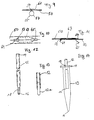
- FIG. 1 is a first embodiment of the invention Device 1 shown.
- a support 10 for support of plants and parts of plants consists of a holder 12, an actuator 20, a spacer 40 and one Support element 50.
- a floor anchor 13 is placed on the holder 12, which is inserted into the soil 3 surrounding a plant 2 is.
- a marking element 70 is on the support 10 put on.
- FIG. 2 shows a first embodiment of the actuating element 20 shown.
- the control element 20 shown in FIG. 2 first embodiment consists of an upper part 28 and a Lower part 30, which is axially rotatably connected to one another are.
- the adjusting element passes through the upper part 28 and lower part 30 20 a through axial bore 22 which the Longitudinal axis of the actuator 20 forms. Through this hole 22, the actuating element 20 can be placed on the holder 12 and adjustable in height along the holder 12.
- the lower part 30 and the upper part 28 of the actuating element 20 are independent of one another rotatable around the holder 12.
- Upper part 28 and lower part 30 of the actuating element 20 point transversely to the bore 22 extending holes 24, which as a bearing serve for spacers 40.
- the spacers 40 are slidable and rotatable along the bores 24.
- the top 28 of the actuating element 20 is provided with slots 26 which are guided parallel to the bore 22 or to the bore 24.
- the Slots 26 serve as bearings for the support element 50.
- a second embodiment of the actuating element 20 is shown. Like the control element 20 according to FIG. 2, this has an upper part 32, which largely corresponds to the upper part 28 of the control element 20 from FIG. 2.
- the upper part 32 of the actuating element 20 from FIGS. 3 to 5 also has bores 24 as bearings for spacer elements 40 and slots 26 as bearings for supporting elements 50.
- a lower part 34 of the actuating element 20 from FIGS. 3 to 5 is designed as a plate axially rotatably connected to the upper part 32.
- the upper part 32 has an axial bore 36 and the lower part 34 has an axial bore 38, the bore 38 of the lower part 34 being offset eccentrically from the bore 36 of the upper part 32.
- the lower part 34 is rotated relative to the upper part 32 such that the bores 36 and 38 are aligned and the adjusting element 20 can be displaced.
- the lower part 32 is rotated such that the bores 36 and 48 become out of alignment and the actuating element 20 is jammed against the holder 12.
- the adjusting element 20 according to FIGS. 3 to 5 can be on its Upper and lower parts 32, 34 with a tactile and visible Marking, for example with raised arrows or the like, be provided, which allow it, optically and / or sensory determine in which position the Bores 36, 38 are located relative to one another, i.e. to determine whether the control element in a released or locked state located.
- the control element 20 according to the 3 to 5 between its upper part 32 and its lower part also be provided with a catch, which is then effective becomes when the clamping effect of the twisted against each other Upper and lower parts 32.34 is largest.
- Such Detent also allows an acoustic control of the optimal Clamping effect of the actuating element 20 against the holder 12.
- the adjusting elements 20 according to FIGS. 2-5 consist of plastic, so that a desired flexibility of the slots 26th is guaranteed, whereby support elements 50 with a greater thickness than the width of the slots 26, can be inserted into the slots 26.
- FIG. 6-8 are exemplary embodiments of support elements 50 of the device 1 according to the invention.
- This Support elements are flexible bands made of a suitable one Plastic.
- the support element 50 from FIG. 6 points uniformly circular holes 51 spaced apart from one another. These holes 51 serve ends 52 and 54 of the support element 50 to be connected to one another, spacer elements 40 or holder 12 pick up or parts of plants using wire or otherwise suitable way to connect with the holes 51.
- FIG. 7 is a second embodiment of a support element 50 shown. This faces the support element 50 from Fig. 6 elongated holes 53, which in vertical slots flow out. This can be advantageous if in the elongated holes 53 fasteners 55 shown in Fig. 9 or conventional serrated plastic strips, for example cable ties, Should be inserted When inserting plastic strips the plastic strips can be in the elongated holes 53 be twisted so that they are vertical Slits slide and are thereby fixed to the support member 50.
- the fastener 55 shown in Fig. 9 consists of an open ring 57, the free ends 59 and 61 are formed so that they engage behind the support member 50 when inserted into a hole 53 of the support member 50. With this fastening element 55, plant parts can be connected to the support element 50. If 57 plastic strips are used instead of the rings, loops of any length can be formed.
- FIG. 8 is a third embodiment of the support element 50 shown. Across the edges 56 and 58 of the support member 50 run 50 slots 60 and 62. In these slots 60 and 62 plant parts to be supported fixed with wire or tape.
- 10 and 11 is a preferred embodiment of the Connection of the free ends 52 and 54 of the support element 50 by means of a clamp 63 serving as a connecting element shown.
- Ends 64 and 65 are here in the immediate Proximity to holes 51 located at ends 54 and 52 performed and for closing the support member 50 in a ring shape bent over. It is also possible to use the clamp 63 to have several To connect support elements 50 together.
- a holder 12 is shown in FIG.
- the holder 12 is a metal tube with a rear end 14 and a front End 16.
- the front end 16 has a taper 18. Through this taper 18, the holder 12 can in another Holder 12 can be inserted.
- the diameter of the taper 18 is dimensioned so that it has an adequate clamping fit in another holder.
- a not shown Spacer 40 has the same as holder 12 12 shows a rear end 42 and a front end 44 with the front end 44 as well as the holder 12 a taper 46 is provided.
- the diameter of the spacer 40 corresponds to the diameter of the holder 12, so that these each as a spacer 40 or as Holder 12 can be used and connected together.
- FIG. 13 is a second embodiment in longitudinal section of the holder 12 shown.
- This holder 12 points in contrast to the holder 12 from FIG. 12 no taper at its end on, but is provided with a pin 12a, which in the open end of the holder 12 is inserted.
- An end of Pin 12a projects beyond the open end of holder 12, that this end is inserted into the open end of another holder can and thus the two holders together can be connected.
- the pin 12a can also be used for connection two spacers can be used.
- a floor anchor 13 is shown.
- the ground anchor 13 has a square profile, each side with a longitudinal groove is provided so that the ground anchor has approximately the cross-sectional shape of a cross.
- a hole 15 made centrally in the ground anchor 13 serves the holder of the holder 12. To possibly in the hole 15 The hole is easy to remove penetrated earth 15 alongside with incisions cut into the fillets Provide slots 17.
- One at one end of the floor anchor 13 located tip 19 is used to insert the ground anchor in mineral soil 3.
- the floor anchor 13 is provided with a plate 11 which ensures that the ground anchor 13 is not too deep in the mineral soil 3 can be inserted and also as an optical Help for the correct insertion depth of the ground anchor 13 serves. This ensures that when inserting several Ground anchor 13, the ground anchor 13 always the same insertion depth have, whereby inserted into the ground anchor 13 Holder 12 can also have the same height.
- a support 10 is shown on the holder 12 a marking element 70 is attached.
- This marker element 70 has a frame 72 which, as in FIG. 16, consisting of an upper part 76 and a lower part 74 consists.
- the upper part 76 is on the lower part 74 by a Snap lock 82 placed.
- the top 76 is at least partially transparent, so that one on the lower part 74 applied marking or a between lower part 74 and Top 76 inserted sheet through the top 76 remains recognizable and legible.
- On the back 78 of the lower part 74 is a sleeve 80 attached, the diameter corresponds to the diameter of the holder and onto the holder 12 can be plugged on.
- the marking element 70 ensures that, as in FIG. 15 shown, even in winter when the plant 2 is not above ground Parts more, the plant 2 identifiable remains and can be located.
- 17 to 19 and 22 to 28 are various possible combinations of the elements of the device.
- 17 is the support member provided with holes 51 50 as a closed ring in two opposite one another Adjustment elements 20 stored.
- the control elements 20 are on Holder 12 attached. Through the support member 20 is a shrub-like plant 2 supported.
- Another control element 20 is on the left in Fig. 17 holder 12 above the Plant 2 and serves to help plant 2 grow taller to be able to be provided with a further support element 50.
- Fig. 18 is another embodiment of the Device 1 shown. In this configuration there are four Adjusting elements 20 mounted one above the other on a holder 12. The actuating elements 20 are provided with spacer elements 40, which serve to support plant 2.
- FIG. 19 is another embodiment of the Device 1 shown.
- the one shown in Figs. 20 and 21 Wall bracket 90 is substantially U-shaped and has one bore 96 extending through both legs 92 and 94. Through a second bore 98, the wall bracket 90 is by means of suitable means, such as one shown in FIG Screw 100, attachable to a building wall or the like.
- Fig. 22 there is a further design option in supervision the device 1 shown, in which two spacer elements 40 parallel to each other in an actuator 20 are stored.
- the space between the two spacers 40 can be used to support parts of plants be so that the spacers 40 function take over the support member 50.
- 23 and 24 are combinations of multiple devices 1 shown together.
- 23 shows the arrangement of the device as a rectangular frame
- Fig. 24 shows the design of the device as a gallery for use Edges away.
- the spacer elements shown there are different Length can be in one piece or by inserting one into the other several spacer elements can be formed.
- 25 to 28 show further possible combinations of actuators 20, support members 50 and spacers 40, with the support element 50 shown in FIG. 27 for stiffening the support element 50, spacer elements 40 are plugged in.
- FIG. 28 it is shown that by the Flexibility of the support element 50 also an oval configuration of the support element 50 is possible.
- FIG. 29 shows a top view of an actuating element 20, in the slot 26 of which a support element 50 is introduced such that both ends 52, 54 of the support element 50 are located in the slot 26 and abut one another.
- ends 52, 54 of the band-shaped support element 50 do not have to be connected separately, for example by wire, rings or the like, to form a ring. It is also possible to clamp one end of the holding element 50 in a slot 26 and the other end of the holding element 50 in the opposite slot 26 of the actuating element.
Landscapes
- Life Sciences & Earth Sciences (AREA)
- Environmental Sciences (AREA)
- Supports For Plants (AREA)
Abstract
Description
Bei der Verwendung der erfindungsgemäßen Vorrichtung in Pflanzgärten, botanischen Gärten, Gewächshäusern, Laboratorien oder dergleichen ist auch eine Individualisierung der zu stützenden Pflanzen mittels (wetterfester) Markierungen nötig. Diese Markierungen lasen sich aber nur schwer an den bislang bekannten Vorrichtungen anbringen, so daß diese Markierungen meist neben den Markierungen in den Boden gesteckt werden. Da viele Stauden und Blumen aber im Winter nicht mehr über die Bodenoberfläche hinausragen, ist das Auffinden dieser Pflanzen, beispielsweise um die Wurzel, Knollen oder Zwiebeln umzusetzen, schwierig. Eine auf die Vorrichtung aufgesetzte Markierung erleichtert daher das Auffinden der Pflanzen im Winter.
- Fig. 1
- ein Ausführungsbeispiel der erfindungsgemäßen Vorrichtung von der Seite,
- Fig. 2
- die perspektivische Ansicht einer bevorzugten Ausführungsform eines Stellelements der erfindungsgemäßen Vorrichtung,
- Fig. 3
- eine Seitenansicht zweier Stellelemente einer zweiten Ausführungsform,
- Fig. 4
- die Seitenansicht einer zweiten Ausführungsform eines Stellelements der erfindungsgemäßen Vorrichtung,
- Fig. 5
- die Draufsicht auf das Stellelement aus Fig. 4,
- Fig. 6
- eine Teilansicht eines Stützelements der erfindungsgemäßen Vorrichtung von der Seite,
- Fig. 7
- die Teilansicht einer zweiten Ausführungsform eines Stützelements der erfindungsgemäßen Vorrichtung von der Seite,
- Fig. 8
- die Teilansicht einer dritten Ausführungsform des Stützelements der erfindungsgemäßen Vorrichtung von der Seite,
- Fig. 9
- die Draufsicht auf ein Befestigungselement der erfindungsgemäßen Vorrichtung,
- Fig. 10
- die Ansicht eines Verbindungselements des Stützelements von hinten,
- Fig. 11
- die Ansicht des Verbindungselements aus Fig. 10 von oben,
- Fig. 12
- die Teilansicht einer bevorzugten Ausführungsform eines Halters der erfindungsgemäßen Vorrichtung von der Seite,
- Fig. 13
- die Teilansicht einer weiteren Ausführungsform eines Halters der erfindungsgemäßen Vorrichtung im Längsschnitt,
- Fig. 14
- einen Bodenanker eines Halters der erfindungsgemäßen Vorrichtung von der Seite,
- Fig. 15
- eine weitere Ausführungsform der erfindungsgemäßen Vorrichtung von der Seite,
- Fig. 16
- die Teilansicht eines Markierungselements der erfindungsgemäßen Vorrichtung von der Seite,
- Fig. 17
- ein Ausführungsbeispiel der erfindungsgemäßen Vorrichtung von vorne,
- Fig. 18
- ein weiteres Ausführungsbeispiel der erfindungsgemäßen Vorrichtung von der Seite,
- Fig. 19
- ein weiteres Ausführungsbeispiel der erfindungsgemäßen Vorrichtung,
- Fig. 20
- einen Wandhalter eines Halters der erfindungsgemäßen Vorrichtung von der Seite,
- Fig. 21
- den Wandhalter aus Fig. 20 von oben,
- Fig. 22
- ein weiteres Ausführungsbeispiel der erfindungsgemäßen Vorrichtung von oben,
- Fig. 23
- die perspektivische Ansicht einer weiteren Ausgestaltung der erfindungsgemäßen Vorrichtung,
- Fig. 24
- die perspektivische Ansicht einer weiteren Ausführungsform der erfindungsgemäßen Vorrichtung,
- Fig. 25
- eine Ausführungsform der erfindungsgemäßen Vorrichtung von oben,
- Fig. 26
- eine weitere Ausgestaltung der erfindungsgemäßen Vorrichtung von oben,
- Fig. 27
- eine weitere Ausgestaltung der erfindinngsgemäßen Vorrichtung von oben,
- Fig. 28
- eine weitere Ausgestaltung der erfindungsgemäßen Vorrichtung von oben, und
- Fig. 29
- eine weitere Ausgestaltung der erfindungsgemäßen Vorrichtung von oben.
Zum Verschieben des Stellelements 20 gemäß den Fig. 3 bis 5 wird das Unterteil 34 gegenüber dem Oberteil 32 so verdreht, daß die Bohrungen 36 und 38 fluchten und das Stellelement 20 verschoben werden kann. Umgekehrt wird zur Festlegung des Stellelements 20 aus Fig. 3 bis 5 das Unterteil 32 so verdreht, daß die Bohrungen 36 und 48 außer Flucht geraten und sich das Stellelement 20 gegen den Halter 12 verklemmt.
Werden anstelle der Ringe 57 übliche Kunststoffbänder verwendet, können beliebig lange Schlaufen gebildet werden.
Es ist auch möglich, ein Ende des Halteelements 50 in einen Schlitz 26, und das andere Ende des Halteelements 50 in den gegenüberliegenden Schlitz 26 des Stellelements einzuklemmen.
Claims (29)
- Vorrichtung zum Ausrichten von Pflanzen mit einer Stütze (10) zum Abstützen von Pflanzen und Pflanzenteilen, bestehend aus mindestens einem Halter (12), aus mindestens einem Stellelement (20), welches an dem Halter (12) höhenverstellbar anbringbar ist, und aus mindestens einem Stützelement (50), welches die zu stützende Pflanze zumindest teilweise umgreift, wobei das Stützelement (50) längenverstellbar ist und wobei der Abstand zwischen Stellelement (20) und Stützelement (50) durch ein Abstandselement (40) verstellbar ist, dadurch gekennzeichnet , daß das Stellelement (20) zur Halterung jeweils des Stützelements (50) und des Abstandselements (40) ausgebildet ist, wobei das Abstandselement (40) zur Halterung des Stützelements (50) und zur Verbindung mit mindestens einem weiteren Stellelement (20) ausgebildet ist, oder wobei das Abstandselement (40) als Stützelement (50) ausgebildet ist.
- Vorrichtung nach Anspruch 1, dadurch gekennzeichnet , daß das Stellelement (20) aus einem Oberteil (28;32) und einem Unterteil (30;34) besteht, welche drehbar miteinander verbunden sind und eine gemeinsame, dem Durchmesser des Halters (12) entsprechende und die Längsachse bildende zentrale Bohrung (22;36,38) aufweisen, wobei das Stellelement (20) mindestens einen senkrechten Schlitz (26) zur Aufnahme des Stützelements (50) aufweist.
- Vorrichtung nach Anspruch 1 oder 2, dadurch gekennzeichnet , daß das Stellelement (20) mindestens eine als Lager für das Abstandselement (40) dienende, quer zur Längsachse (22) verlaufende Bohrung (24) aufweist.
- Vorrichtung nach Anspruch 2 und 3, dadurch gekennzeichnet , daß der Schlitz (26) parallel zur Längsachse (22) bzw. zur Bohrung (24) geführt ist.
- Vorrichtung nach Anspruch 2 bis 4, dadurch gekennzeichnet , daß der Schlitz (26) in die Bohrung (24) mündet.
- Vorrichtung nach einem der Ansprüche 1 bis 5, dadurch gekennzeichnet , daß das Stellelement (20) um den Halter (12) drehbar ist.
- Vorrichtung nach einem der Ansprüche 2 bis 6, dadurch gekennzeichnet , daß das Unterteil (34) des Stellelements (20) mit einer gegenüber der Bohrung (36) des Oberteils (32) exzentrisch versetzten Bohrung (38) versehen ist.
- Vorrichtung nach Anspruch 1, dadurch gekennzeichnet , daß Stützelement (50) ein flexibles Band ist.
- Vorrichtung nach Anspruch 1 und 8, dadurch gekennzeichnet , daß Enden (52, 54) des Bandes (50) miteinander verbindbar sind.
- Vorrichtung nach Anspruch 1 und einem der Ansprüche 8 und 9, dadurch gekennzeichnet , daß die Dicke des Stützelements (50) der Breite des Schlitzes (26) entspricht.
- Vorrichtung nach Anspruch 1 und einem der Ansprüche 8 - 10, dadurch gekennzeichnet , daß das Stützelement (50) voneinander beabstandete Löcher (51; 53) aufweist.
- Vorrichtung nach Anspruch 11, dadurch gekennzeichnet , daß in die Löcher (51; 53) des Bandes (50) mindestens ein Befestigungselement (55) einbringbar ist.
- Vorrichtung nach Anspruch 12, dadurch gekennzeichnet , daß das Befestigungselement (55) ein federnder, einseitig offener Ring (57) ist, dessen freie Enden (59, 61) abgewinkelt sind.
- Vorrichtung nach Anspruch 1 und einem der Ansprüche 11 und 12, dadurch gekennzeichnet , daß der Durchmesser der Löcher (51; 53) dem Durchmesser des Abstandselements (40) entspricht.
- Vorrichtung nach Anspruch 1 und einem der Ansprüche 8 - 14, dadurch gekennzeichnet , daß das Stützelement (50) an seinen Kanten (56, 58) mit Schlitzen (60, 62) versehen ist.
- Vorrichtung nach Anspruch 1, dadurch gekennzeichnet , daß der Halter (12) mit mindestens einem weiteren Halter (12) axial verbindbar ist.
- Vorrichtung nach Anspruch 1, dadurch gekennzeichnet , daß der Halter (12) mit mindestens einem weiteren Halter (12) axial steckbar verbindbar ist.
- Vorrichtung nach Anspruch 1 und einem der Ansprüche 16 und 17, dadurch gekennzeichnet , daß der Halter (12) rohrförmig ist, wobei ein Ende (16) des Halters (12) mit einer Verjüngung (18) versehen ist.
- Vorrichtung nach Anspruch 1 und einem der Ansprüche 16 - 18, dadurch gekennzeichnet , daß der Halter (12) mit einem Bodenanker (13) versehbar ist.
- Vorrichtung nach Anspruch 19, dadurch gekennzeichnet , daß der Bodenanker (13) eine zentrale Bohrung (15) zur Aufnahme des Halters (12), an einem Ende eine Spitze (19) und am anderen Ende einen Teller (11) aufweist.
- Vorrichtung nach Anspruch 20, dadurch gekennzeichnet , daß die Bohrung (15) längsseits mit mindestens einem Schlitz (17) versehen ist.
- Vorrichtung nach Anspruch 1 und einem der Ansprüche 16 - 18, dadurch gekennzeichnet , daß der Halter (12) mit einem Wandbefestigungselement (90) versehbar ist.
- Vorrichtung nach Anspruch 1, dadurch gekennzeichnet , daß das Abstandselement (40) mit wenigstens einem weiteren Abstandselement (40) axial verbindbar ist.
- Vorrichtung nach Anspruch 1, dadurch gekennzeichnet , daß das Abstandselement (40) mit wenigstens einem weiteren Abstandselement (40) axial steckbar verbindbar ist.
- Vorrichtung nach Anspruch 1 und einem der Ansprüche 23 und 24, dadurch gekennzeichnet , daß das Abstandselement (40) rohrförmig ist, wobei ein Ende (44) des Abstandselements (40) mit einer Verjüngung (46) versehen ist.
- Vorrichtung nach Anspruch 1 und einem der Ansprüche 16 - 18 und 23 - 25, dadurch gekennzeichnet , daß Halter (12) und Abstandselement (40) den gleichen Querschnitt und den gleichen Durchmesser aufweisen.
- Vorrichtung nach Anspruch 1, dadurch gekennzeichnet , daß die Vorrichtung (1) mit einem Markierungselement (70) versehbar ist.
- Vorrichtung nach Anspruch 27, dadurch gekennzeichnet , daß das Markierungselement (70) aus einem zweiteiligen Rahmen (72) mit einem Unterteil (74) und einem Oberteil (76) besteht, wobei das Oberteil (76) zumindest teilweise transparent ist.
- Vorrichtung nach Anspruch 28, dadurch gekennzeichnet , daß an der Rückseite (78) des Unterteils (74) im Winkel zur Ebene des Unterteils (74) eine Hülse (80) angebracht ist.
Applications Claiming Priority (2)
| Application Number | Priority Date | Filing Date | Title |
|---|---|---|---|
| DE19723546 | 1997-06-05 | ||
| DE1997123546 DE19723546C2 (de) | 1997-06-05 | 1997-06-05 | Vorrichtung zum Abstützen von Pflanzen |
Publications (2)
| Publication Number | Publication Date |
|---|---|
| EP0882391A2 true EP0882391A2 (de) | 1998-12-09 |
| EP0882391A3 EP0882391A3 (de) | 2000-03-22 |
Family
ID=7831455
Family Applications (1)
| Application Number | Title | Priority Date | Filing Date |
|---|---|---|---|
| EP98109992A Withdrawn EP0882391A3 (de) | 1997-06-05 | 1998-06-02 | Vorrichtung zum Ausrichten von Pflanzen |
Country Status (2)
| Country | Link |
|---|---|
| EP (1) | EP0882391A3 (de) |
| DE (1) | DE19723546C2 (de) |
Cited By (4)
| Publication number | Priority date | Publication date | Assignee | Title |
|---|---|---|---|---|
| US6588147B2 (en) * | 2000-10-19 | 2003-07-08 | Norwood Industries Pty Ltd. | Juvenile plant holding device |
| AU783812B2 (en) * | 2000-10-19 | 2005-12-08 | Norwood Industries Pty Ltd | Holding device |
| US20170172073A1 (en) * | 2015-12-18 | 2017-06-22 | Barend J. Van Den Heever | Supporting clamp apparatus and process |
| CN112136548A (zh) * | 2020-10-09 | 2020-12-29 | 汤小荔 | 一种用于柑橘幼苗种植的矫正定位装置 |
Families Citing this family (5)
| Publication number | Priority date | Publication date | Assignee | Title |
|---|---|---|---|---|
| DE20217318U1 (de) * | 2002-11-07 | 2003-12-18 | Ch. Baur Formschaumtechnik Gmbh | Pflanzenfixiervorrichtung |
| DE202005003890U1 (de) * | 2005-03-10 | 2006-07-20 | Steinberger, Barbara | Pflanzenstützvorrichtung |
| CN106900483A (zh) * | 2017-01-13 | 2017-06-30 | 广州子赫建筑装饰有限公司 | 一种市政绿化用的树木扶正装置 |
| CN108575540A (zh) * | 2018-04-19 | 2018-09-28 | 贾红娜 | 一种新型园林育苗装置 |
| CN108401781B (zh) * | 2018-06-07 | 2020-02-07 | 正坚建设有限公司 | 园林绿化树木支撑装置 |
Citations (2)
| Publication number | Priority date | Publication date | Assignee | Title |
|---|---|---|---|---|
| DE2809388A1 (de) | 1978-03-04 | 1979-09-13 | Wolf Dieter Norra | Wachstumverstellbarer baum- und pflanzenhalter |
| DE8811068U1 (de) | 1988-09-01 | 1988-11-17 | Haas, Heidi, 7981 Gruenkraut, De |
Family Cites Families (14)
| Publication number | Priority date | Publication date | Assignee | Title |
|---|---|---|---|---|
| US1758839A (en) * | 1929-08-07 | 1930-05-13 | Kelsey Theodore | Plant support |
| DE536496C (de) * | 1930-12-05 | 1931-10-23 | Ella Telle Geb Hallama | Verstellbarer, Stauden- und Strauchhalter |
| GB915923A (en) * | 1961-03-10 | 1963-01-16 | Frank Harlow | Improvements in or relating to locking devices |
| FR1292047A (fr) * | 1961-06-13 | 1962-04-27 | Pieu ou poteau à mettre en place verticalement dans le sol, en particulier pieu pour une enceinte | |
| AT282247B (de) * | 1968-11-13 | 1970-06-25 | Josef Leitner | Baumstütze |
| FR2215162B2 (de) * | 1972-07-13 | 1976-05-14 | Paniez Jean Marie | |
| DE3009354A1 (de) * | 1980-03-12 | 1981-10-01 | Multibinder Frei Gmbh, 7597 Rheinau | Vorrichtung zum stuetzen und halten von pflanzen |
| DE3224569A1 (de) * | 1982-07-01 | 1984-01-05 | Biege-, Form- & Stanzteile oHG Döpper & Dittmann, 5800 Hagen | Stuetzdraht-traegerpfahl fuer den weinbau |
| US4480403A (en) * | 1983-07-28 | 1984-11-06 | Williams Wilburn R | Apparatus for supporting a cantilevered beam from a T-shaped post |
| DE3433374A1 (de) * | 1984-09-12 | 1986-03-20 | Brigitte 2943 Esens Rode | Vorrichtung zum stuetzen von pflanzen |
| DE8812297U1 (de) * | 1988-09-29 | 1988-12-15 | Zander, Juergen, 5880 Luedenscheid, De | |
| DE9213577U1 (de) * | 1992-10-08 | 1993-05-27 | Stolten, Hans-Werner, 4500 Osnabrueck, De | |
| DE19512530C2 (de) * | 1995-04-05 | 1997-03-27 | Jochum Geb Rexin Elisabeth | Stützvorrichtung für knickgefährdete Bäumchen oder einen Stamm bildende Jungpflanzen |
| US5542210A (en) * | 1995-07-03 | 1996-08-06 | Hupfl; Martin | Apparatus for supporting plantlife growing in a ground area |
-
1997
- 1997-06-05 DE DE1997123546 patent/DE19723546C2/de not_active Expired - Fee Related
-
1998
- 1998-06-02 EP EP98109992A patent/EP0882391A3/de not_active Withdrawn
Patent Citations (2)
| Publication number | Priority date | Publication date | Assignee | Title |
|---|---|---|---|---|
| DE2809388A1 (de) | 1978-03-04 | 1979-09-13 | Wolf Dieter Norra | Wachstumverstellbarer baum- und pflanzenhalter |
| DE8811068U1 (de) | 1988-09-01 | 1988-11-17 | Haas, Heidi, 7981 Gruenkraut, De |
Cited By (4)
| Publication number | Priority date | Publication date | Assignee | Title |
|---|---|---|---|---|
| US6588147B2 (en) * | 2000-10-19 | 2003-07-08 | Norwood Industries Pty Ltd. | Juvenile plant holding device |
| AU783812B2 (en) * | 2000-10-19 | 2005-12-08 | Norwood Industries Pty Ltd | Holding device |
| US20170172073A1 (en) * | 2015-12-18 | 2017-06-22 | Barend J. Van Den Heever | Supporting clamp apparatus and process |
| CN112136548A (zh) * | 2020-10-09 | 2020-12-29 | 汤小荔 | 一种用于柑橘幼苗种植的矫正定位装置 |
Also Published As
| Publication number | Publication date |
|---|---|
| DE19723546A1 (de) | 1998-12-10 |
| DE19723546C2 (de) | 1999-09-02 |
| EP0882391A3 (de) | 2000-03-22 |
Similar Documents
| Publication | Publication Date | Title |
|---|---|---|
| DE69906191T2 (de) | Vorrichtung zur Befestigung einer Antenne | |
| EP0882391A2 (de) | Vorrichtung zum Ausrichten von Pflanzen | |
| EP0714334B1 (de) | Spannfutter und zugehöriges werkzeug | |
| DE60038654T2 (de) | Klemmhalterung für Stütz- und Verbindungselemente | |
| DE2353418C3 (de) | Federnde Klemmvorrichtung zur Befestigung eines flächigen ersten Teilelements an einem flächigen zweiten Teilelement | |
| DE1184544B (de) | Vorrichtung zum Aufbinden einer wachsenden Pflanze mit Hilfe eines drahtfoermigen Elements | |
| EP0416201B1 (de) | Vorrichtung zur Sicherung von Einzugsspalten an Bandförderern | |
| DE3606113C2 (de) | Hilfsvorrichtung für den Bausektor | |
| DE3009354A1 (de) | Vorrichtung zum stuetzen und halten von pflanzen | |
| AT401186B (de) | Dachleitungshalter, der zur auflage auf einen firstziegel bestimmt ist | |
| DE2524402C3 (de) | Höhenanpaßbarer Pfosten für Trennwände | |
| EP2572563A1 (de) | Federzahnegge | |
| DE1270759B (de) | Feststeller fuer Wolkenstores | |
| AT413722B (de) | Distanzhalter | |
| EP0319714B1 (de) | Backen für Skibindungen | |
| DE1154245B (de) | Halter zum Befestigen von Tragschienen fuer Gardinen, Vorhaenge u. dgl. | |
| DE20217318U1 (de) | Pflanzenfixiervorrichtung | |
| DE1509538C (de) | Lamellenjalousie mit lotrecht angeordneten und um ihre Längsachse gemeinsam schwenkbaren Lamellen | |
| DE3028814C2 (de) | Schraubbefestigung von Blitzableiterleitungen an Leitungshaltern o.dgl. | |
| DE2705250C3 (de) | Vorrichtung zum Aufwickeln von Gurten, Bändern o.dgl. insbesondere von Rolladengurten | |
| WO2024028177A1 (de) | Angelvorrichtung für einen gummiköder | |
| AT405226B (de) | Hängevorrichtung für elektrische leitungen | |
| DE202011003539U1 (de) | Rankhilfe für hochwachsende Pflanzen, insbesondere für Tomatenstauden | |
| DE2050436A1 (de) | Rohrbandschelle | |
| DE8625101U1 (de) | Pflanzen-Haltevorrichtung |
Legal Events
| Date | Code | Title | Description |
|---|---|---|---|
| PUAI | Public reference made under article 153(3) epc to a published international application that has entered the european phase |
Free format text: ORIGINAL CODE: 0009012 |
|
| AK | Designated contracting states |
Kind code of ref document: A2 Designated state(s): AT BE CH CY DE DK ES FI FR GB GR IE IT LI LU MC NL PT SE |
|
| AX | Request for extension of the european patent |
Free format text: AL;LT;LV;MK;RO;SI |
|
| RIC1 | Information provided on ipc code assigned before grant |
Free format text: 7A 01G 9/12 A, 7A 01G 17/14 B, 7A 01G 17/12 B |
|
| PUAL | Search report despatched |
Free format text: ORIGINAL CODE: 0009013 |
|
| AK | Designated contracting states |
Kind code of ref document: A3 Designated state(s): AT BE CH CY DE DK ES FI FR GB GR IE IT LI LU MC NL PT SE |
|
| AX | Request for extension of the european patent |
Free format text: AL;LT;LV;MK;RO;SI |
|
| AKX | Designation fees paid | ||
| REG | Reference to a national code |
Ref country code: DE Ref legal event code: 8566 |
|
| STAA | Information on the status of an ep patent application or granted ep patent |
Free format text: STATUS: THE APPLICATION IS DEEMED TO BE WITHDRAWN |
|
| 18D | Application deemed to be withdrawn |
Effective date: 20000923 |