EP0881630A2 - Dispositif d'exposition pour matrice de disque optique - Google Patents
Dispositif d'exposition pour matrice de disque optique Download PDFInfo
- Publication number
- EP0881630A2 EP0881630A2 EP98109638A EP98109638A EP0881630A2 EP 0881630 A2 EP0881630 A2 EP 0881630A2 EP 98109638 A EP98109638 A EP 98109638A EP 98109638 A EP98109638 A EP 98109638A EP 0881630 A2 EP0881630 A2 EP 0881630A2
- Authority
- EP
- European Patent Office
- Prior art keywords
- light
- laser light
- optical element
- exposure device
- optical disc
- Prior art date
- Legal status (The legal status is an assumption and is not a legal conclusion. Google has not performed a legal analysis and makes no representation as to the accuracy of the status listed.)
- Granted
Links
Images


Classifications
-
- G—PHYSICS
- G11—INFORMATION STORAGE
- G11B—INFORMATION STORAGE BASED ON RELATIVE MOVEMENT BETWEEN RECORD CARRIER AND TRANSDUCER
- G11B7/00—Recording or reproducing by optical means, e.g. recording using a thermal beam of optical radiation by modifying optical properties or the physical structure, reproducing using an optical beam at lower power by sensing optical properties; Record carriers therefor
- G11B7/24—Record carriers characterised by shape, structure or physical properties, or by the selection of the material
- G11B7/26—Apparatus or processes specially adapted for the manufacture of record carriers
- G11B7/261—Preparing a master, e.g. exposing photoresist, electroforming
-
- G—PHYSICS
- G02—OPTICS
- G02B—OPTICAL ELEMENTS, SYSTEMS OR APPARATUS
- G02B7/00—Mountings, adjusting means, or light-tight connections, for optical elements
- G02B7/02—Mountings, adjusting means, or light-tight connections, for optical elements for lenses
- G02B7/04—Mountings, adjusting means, or light-tight connections, for optical elements for lenses with mechanism for focusing or varying magnification
- G02B7/10—Mountings, adjusting means, or light-tight connections, for optical elements for lenses with mechanism for focusing or varying magnification by relative axial movement of several lenses, e.g. of varifocal objective lens
-
- G—PHYSICS
- G11—INFORMATION STORAGE
- G11B—INFORMATION STORAGE BASED ON RELATIVE MOVEMENT BETWEEN RECORD CARRIER AND TRANSDUCER
- G11B7/00—Recording or reproducing by optical means, e.g. recording using a thermal beam of optical radiation by modifying optical properties or the physical structure, reproducing using an optical beam at lower power by sensing optical properties; Record carriers therefor
- G11B7/08—Disposition or mounting of heads or light sources relatively to record carriers
- G11B7/085—Disposition or mounting of heads or light sources relatively to record carriers with provision for moving the light beam into, or out of, its operative position or across tracks, otherwise than during the transducing operation, e.g. for adjustment or preliminary positioning or track change or selection
- G11B7/08547—Arrangements for positioning the light beam only without moving the head, e.g. using static electro-optical elements
- G11B7/08558—Arrangements for positioning the light beam only without moving the head, e.g. using static electro-optical elements using acousto-optical elements
-
- G—PHYSICS
- G11—INFORMATION STORAGE
- G11B—INFORMATION STORAGE BASED ON RELATIVE MOVEMENT BETWEEN RECORD CARRIER AND TRANSDUCER
- G11B7/00—Recording or reproducing by optical means, e.g. recording using a thermal beam of optical radiation by modifying optical properties or the physical structure, reproducing using an optical beam at lower power by sensing optical properties; Record carriers therefor
- G11B7/12—Heads, e.g. forming of the optical beam spot or modulation of the optical beam
- G11B7/135—Means for guiding the beam from the source to the record carrier or from the record carrier to the detector
- G11B7/1372—Lenses
- G11B7/1374—Objective lenses
-
- G—PHYSICS
- G11—INFORMATION STORAGE
- G11B—INFORMATION STORAGE BASED ON RELATIVE MOVEMENT BETWEEN RECORD CARRIER AND TRANSDUCER
- G11B7/00—Recording or reproducing by optical means, e.g. recording using a thermal beam of optical radiation by modifying optical properties or the physical structure, reproducing using an optical beam at lower power by sensing optical properties; Record carriers therefor
- G11B7/12—Heads, e.g. forming of the optical beam spot or modulation of the optical beam
- G11B7/135—Means for guiding the beam from the source to the record carrier or from the record carrier to the detector
- G11B7/1372—Lenses
- G11B7/1376—Collimator lenses
-
- G—PHYSICS
- G11—INFORMATION STORAGE
- G11B—INFORMATION STORAGE BASED ON RELATIVE MOVEMENT BETWEEN RECORD CARRIER AND TRANSDUCER
- G11B7/00—Recording or reproducing by optical means, e.g. recording using a thermal beam of optical radiation by modifying optical properties or the physical structure, reproducing using an optical beam at lower power by sensing optical properties; Record carriers therefor
- G11B7/12—Heads, e.g. forming of the optical beam spot or modulation of the optical beam
- G11B7/135—Means for guiding the beam from the source to the record carrier or from the record carrier to the detector
- G11B7/1372—Lenses
- G11B2007/13727—Compound lenses, i.e. two or more lenses co-operating to perform a function, e.g. compound objective lens including a solid immersion lens, positive and negative lenses either bonded together or with adjustable spacing
-
- Y—GENERAL TAGGING OF NEW TECHNOLOGICAL DEVELOPMENTS; GENERAL TAGGING OF CROSS-SECTIONAL TECHNOLOGIES SPANNING OVER SEVERAL SECTIONS OF THE IPC; TECHNICAL SUBJECTS COVERED BY FORMER USPC CROSS-REFERENCE ART COLLECTIONS [XRACs] AND DIGESTS
- Y10—TECHNICAL SUBJECTS COVERED BY FORMER USPC
- Y10S—TECHNICAL SUBJECTS COVERED BY FORMER USPC CROSS-REFERENCE ART COLLECTIONS [XRACs] AND DIGESTS
- Y10S430/00—Radiation imagery chemistry: process, composition, or product thereof
- Y10S430/146—Laser beam
Definitions
- This invention relates to a light exposure device for a master optical disc used as a master disc in manufacturing an optical disc formed with pits and grooves for exposing the master optical disc to light.
- a recordable optical disc is formed with concentric grooves or a spirally extending groove.
- an optical disc of the groove-recording type in which information signals are recorded in the grooved portion.
- an optical disc of the land-recording type in which information signals are recorded on lands which are protuberant portions formed between neighboring turns of the groove(s).
- an optical disc of the land-and-groove recording type in which the information signals are recorded in the groove(s) and the lands.
- a master optical disc is prepared in the so-called mastering process, and the optical discs are prepared from the master disc, a father disc, a mother disc and a stamper. That is, in producing an optical disc, a master optical disc having crests and valleys corresponding to the groove(s) and lands formed to high precision is required.
- the portions formed in the master optical disc in register with pits of the optical disc are termed "pit-forming portions", while the portions similarly formed in the master optical disc in register with groove(s) of the optical disc are termed "groove-forming portions".
- a laser light beam is illuminated on a photoresist coated to a pre-set thickness on a glass substrate for forming the pit-forming and groove-forming portions by light exposure. That is, with the master optical disc, the laser light beam is illuminated on the pit-forming and groove-forming portions, and the areas of the photoresist illuminated by the laser light beam are etched during the development process, while the areas thereof other than those illuminated by the laser light beam are cured. This forms the pit-forming portions and the groove-forming portions having the desired shape on the master optical disc.
- the wobbling method As described in Japanese Laying-Open Patent Publication 64-35742, is used. With the wobbling method, the laser light beam illuminated on the photoresist is oscillated along the radius of the master optical disc for forming pits and groove(s) to wider widths.
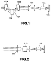
- a light exposure device 101 having a pair of wedge-shaped cylindrical lenses 100A, 100B, as shown in Fig. 1, is used.
- the light exposure device 101 includes a light source, not shown, for radiating a laser light beam, the paired cylindrical lenses 100A, 100B, arranged on the optical axis of the laser light beam radiated from the light source, an acoustic optical element 102, arranged between the paired wedge-shaped cylindrical lenses 100A; 100B; a light condenser lens 103 arranged on the optical axis of the laser light transmitted through the for condensing the laser light wedge-shaped cylindrical lenses 100A, 100B and an objective lens 104 arranged downstream of the focal point position of the light condenser lens 103.
- the laser light transmitted through the paired wedge-shaped cylindrical lenses 100A, 100B has its pre-set direction condensed, while having its direction perpendicular thereto collimated so as to enter the acoustic optical element 102. That is, the laser light entering the acoustic optical element 102 is in the form substantially of a spot having the direction of light condensation as the longitudinal direction.
- the acoustic optical element 102 wobbles the laser light entered thereto in a state in which compression waves of pre-set frequencies are superimposed thereon.
- the compression waves are superimposed from the direction parallel to the longitudinal direction of the substantially linear spot shape for wobbling the laser light.
- the laser light beam wobbled by the acoustic optical element 102 is restored to its original shape; as it is transmitted through the opposite side wedge-shaped cylindrical lens 100B, so as to be illuminated on the condenser lens 103.
- the condenser lens 103 having its focal point position upstream of the objective lens 104, condenses the wobbled laser light on its focal point position.
- the wobbled laser light is exposed to the master optical disc 105 via the objective lens 104.
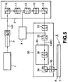
- a light exposure device 110 When the master optical disc is exposed to light by the wobbling method, a light exposure device 110 is sometime used, as shown in Fig.2.
- This light exposure device 110 includes a light source, not shown, a light condenser lens 111 arranged on the optical axis of the laser light outgoing from the light source, an acoustic optical element 112 arranged upstream of the light condenser lens 111 and an objective lens 113 arranged downstream of the focal point of the light condenser lens 111.
- the laser light outgoing from the light source is condensed by the light condenser lens 111 so as to enter the acoustic optical element 112 at a point ahead of the focal point position.
- the acoustic optical element 112 superimposes the compression waves on the laser light.
- the laser light entering the acoustic optical element 112 of the light exposure device 110 has its profile changed to a circular shape.
- the wobbled laser light is exposed via objective lens 113 on a master optical disc 114.
- a master optical disc having crests and valleys formed to high precision by the wobbling method
- the acoustic optical element 102 superimposes the compression wave on the laser light, condensed to a substantially linear light beam, from the direction parallel to the longitudinal direction of the spot shape. If, in the present light exposure device, the high frequency compression wave is used, the longitudinal width of the spot shape is substantially equal to the wavelength of the compression wave. This renders the direction of diffraction of the laser light in the light flux to be non-uniform to cause scattering of the laser light. Thus, in this case, the wobbled laser light exposing the master optical disc to light is not of the desired spot shape.
- the master optical disc is exposed to light in areas other than desired areas, so that the disc cannot have the pit-forming portion or the groove-forming portion of desired shape. That is, the above-described light exposure device has a drawback that it is difficult to perform light exposure so that the pit-forming portions and the groove-forming portions will present the shape of recesses and crests of high precision.
- the acoustic optical element 112 is arranged upstream of the focal point position of the light condenser lens 111. Also, in this case, since the acoustic optical element 112 uses compression waves of high frequency, the laser light of a small spot diameter needs to be supplied.
- the acoustic optical element 112 needs to be arranged in the vicinity of the focal point position of the light condenser lens 111.
- the light deflection by the acoustic optical element 112 becomes smaller the closer the acoustic optical element 112 is arranged towards the focal point position of the light condenser lens 111 in association with the compression waves of higher frequency. That is, in the present light exposure device 110, the laser light is of a small amplitude.
- the above-described light exposure device 110 has a drawback that the master optical disc cannot be exposed to light in register with the groove-forming portion or the pit-forming portion adapted for forming larger wobbling pits.
- the present invention provides a light exposure device for a master optical disc for exposing to light the portions of a photoresist coated on the master optical disc in register with a pre-set pattern carrying recorded information signals including a light condensing optical element for condensing the laser light radiated from a light source, a deflecting optical element for condensing the laser light radiated from the light condensing optical element, and an optical system arranged downstream of the focal point position of the light-condensing optical element for re-imaging the laser light wobbled by the deflecting optical element upstream of an objective lens.
- a light condensing optical element for condensing the laser light radiated from a light source
- a deflecting optical element for condensing the laser light radiated from the light condensing optical element
- an optical system arranged downstream of the focal point position of the light-condensing optical element for re-imaging the laser light wobbled by the deflecting optical element upstream of an objective
- the light exposure device for the master optical disc according to the present invention includes the deflecting optical element at a pre-set position from the focal point position of the light-condensing optical element.
- a laser light beam of a small spot diameter is illuminated on the deflecting optical element. Consequently, the defecting optical element of the light exposure device wobbles the laser light of the small spot diameter, thus assuring optimum wobbling of the laser light beam.
- the optical system of the light exposure device re-images the laser light beam wobbled by the defecting optical element at a desired focal length.
- the light exposure device can set the amplitude of the re-imaged laser light to a pre-set value. That is, with the present light exposure device, the amplitude of the wobbled laser light can be adjusted by the optical system to expose the master optical disc with the laser light wobbled to the desired amplitude.
- the laser light can be wobbled satisfactorily even if the compression wave of a higher frequency is used, while the wobbled laser light can be increased in amplitude.
- a master optical disc can be produced which is high in precision and which has crests and recesses of broader widths.
- Fig. 1 shows the optical path of essential portions of the conventional light exposure device.
- Fig. 2 shows the optical path of essential portions of the conventional light exposure device.
- Fig. 3 shows the structure of a light exposure device for a master optical disc according to the present invention.
- Fig.4 shows the optical path of essential parts of a laser illuminating portion in the light exposure device.
- Fig. 5 shows the structure of a light exposure device for another master optical disc according to the present invention.
- Fig. 6 shows the optical path of essential parts of the laser illuminating portion in the light exposure device shown in Fig.3.
- the light exposure device for the master optical disc is used for forming an optical disc, exemplified by a magneto-optical disc and which is formed with pits as information signals and a groove as a guide groove for tracking servo.
- the light exposure device for the master optical disc includes a laser light source 1 for radiating the laser light, a first optical modulating element 2 for power control, a laser adjustment unit 3 for adjusting the spot diameter of the laser light, a controller 4 for supplying the control signal to the laser adjustment unit 3 and a laser light illuminating portion 5.
- the light exposure device illuminates the wobbled laser light on a pre-set area of the master optical disc 6.
- the master optical disc 6 includes a substantially disc-shaped substrate 7 of glass or the like and a photoresist layer 8 formed on the substrate 7.
- the portions of the photoresist layer 8 in register with the pits of the optical disc are formed with pit-forming portions, while the portions of the optical disc in register with the grooves are formed with groove-forming portions. These pit- and groove-forming portions are formed as recesses.
- the photoresist layer 8 is first formed to a pre-set film thickness on the glass substrate 7.
- the substrate 7 used is planarized to a high degree and has its surface freed of deposited dust and dirt.
- a photoresist is coated on this highly planarized surface.
- the photoresist may be formed on a thin metal layer such as a chromium layer or a primer layer of an organic material, such as a silane coupling agent, formed on the substrate 7.
- the photoresist layer 8 is coated to a precisely controlled film thickness for prescribing the depth of the pit-forming and groove-forming portions.
- a precisely controlled film thickness for prescribing the depth of the pit-forming and groove-forming portions.
- an ellipsometer may be used, or the film thickness may be calculated from the reflectance value.
- the laser adjustment unit 3 includes a first mirror 10 for refracting the laser light reflected from the laser light source 1, and a first lens 11, a second optical modulation element 12, a second lens 13 and a second mirror 14, arranged in this order on the optical axis of the laser light reflected by the first mirror 10.
- the second optical modulation element 12 is connected to the controller 4.
- the optical system 17 includes a collimator lens 20 and a second light condenser lens 21 in this order on the optical axis of the laser light.
- the acoustic optical element 16 is arranged within one-half of the focal length (fl in Fig.4) from the focal point position of the first light collecting lens 15, on the optical axis of the diffracted light of the first light collecting lens 15, as shown in Fig.4.
- This acoustic optical element 16 is connected to the controller 4 so that a compression wave of a higher frequency of the order of 5 MHz is superimposed on the laser light.
- a laser light beam having the shape of a substantially linear spot falls on the acoustic optical element 16 fed with a compression wave having a pre-set frequency.
- the compression wave is supplied to the acoustic optical element from the longitudinal direction of the linear shape of the spot of the incident laser light.
- the compression wave is supplied to the acoustic optical element from the longitudinal direction of the spot shape of the incident laser light. This wobbles the laser light incident on the acoustic optical element at an amplitude A1 shown in Fig.4 at a pre-set frequency.
- the optical system 17 includes a collimator lens 20 and the second light condenser lens 21 in this order on the optical axis of the laser light wobbled by the acoustic optical element 16, as shown in Fig.4.
- the laser light wobbled by the acoustic optical element 16 means the first-order diffracted light diffracted within the acoustic optical element 16.
- the collimator lens 20 is arranged downstream of the focal point position of the first light collecting lens 15.
- the collimator lens 20 is arranged downstream of the focal point position F1 of the first light collecting lens 15 by a distance f2 shown in Fig.4.
- the second light condenser lens 21 is arranged on the optical path of the laser light radiated from the collimator lens 20 and has a focal point position F3 shown as a focal length f3 in Fig.4.
- the amplitude of the laser LW0 at the focal point position F3 is indicated as A2.
- the above-described collimator lens 20 is movable in a direction parallel to the optical axis. That is, with the present optical system 17, the distance f2 from the focal point position F1 of the first light collecting lens 15 to the collimator lens 20 can be set to a desired magnitude.
- the second light condenser lens 21 has a fixed focal point position F3 and a desired focal point distance f3. In order for the focal length f3 to have a desired value, the second light condenser lens 21 is preferably designed as varifocal lens.
- the wobbled laser light beam is illuminated on the photoresist layer 8 for light-exposure of the areas of the photoresist layer 8 in register with the pit forming portions and groove forming portions.
- the pre-set laser light beam is radiated from the laser light source 1 to fall on the first optical modulating element 2.
- the laser light beam radiated from the laser light source 1 is power-controlled in the first optical modulating element 2 so as to be turned into laser light L0.
- the first optical modulating element 2 which modulates the intensity of the incident laser light beam suffices such that the first optical modulating element 2 may be designed to perform opto-electric modulation, acousto-optical modulation or photomagnetic modulation.
- This laser adjustment unit 3 is adapted to turn the laser L0 on and off for exposing to light the portions of the photoresist layer 8 in register with the pit-forming and groove-forming portions.
- the laser light L0 is refracted by the first mirror 10 to fall on the first lens 11.
- the laser light L0 is formed by the first lens 11 into a spot of a pre-set diameter to fall on the second optical modulation element 12.
- This second optical modulation element 12 is fed with a control signal from the controller 4 to transmit or shield the incident laser light L0.
- the second optical modulation element 12 may, for example, be designed as an acousto-optical type modulator.
- the controller 4 manages control to transmit or to shield the laser light L0 when the laser light illuminated on the photoresist layer 8 is or is not in the pit-forming portions or in the groove-forming portions, respectively.
- the laser light L0 transmitted through the second optical modulation element 12 falls on the second lens 13 for collimation.
- the collimated laser light L0 is refracted by the second mirror 14 so as to fall on the laser light illuminating portion 5.
- the laser L0 is collimated in this manner by the laser adjustment unit 3 at a desired timing so as to then fall on the laser light illuminating portion 5.
- the incident laser light L0 is wobbled into the laser light LW0 by the acoustic optical element 16 of the laser light illuminating portion 5, as the deflecting optical element, with the laser light LW0 being illuminated on the master optical disc 6.
- the laser light L0 radiated from the laser adjustment unit 3 falls on the first light collecting lens 15 of the laser light illuminating portion 5.
- This first light collecting lens 15 is a lens having the focal length f1, as shown in Fig.2, and condenses the laser L0 at the focal point position F1.
- the acoustic optical element 16 is arranged on the optical axis of the laser light L0. On the acoustic optical element 16 falls the laser light L0 condensed by the first light collecting lens 15.
- This acoustic optical element 16 is arranged at a position within one/half the focal length f1 from the focal point position F1.
- the laser light L0 with a small spot size is illuminated via the first light collecting lens 15 on the acoustic optical element 16.
- the compression wave is superimposed on the illuminated laser light L0 to wobble the laser light L0.
- the acoustic optical element 16 diffracts the laser light L0 condensed by the first condenser lens 15. From the acoustic optical element 16 is radiated the first-order diffracted light of the diffracted laser light L0.
- the laser light L0 is uniform in the direction of diffraction in the light beam. such that the laser light is not scattered and deflection by the compression wave is uniform in the light beam. Therefore, with the laser light illuminating portion 5, the laser light L0 can be wobbled satisfactorily even if the compression wave is of a higher frequency of approximately 6 MHz.
- the laser light LW0 wobbled with the amplitude A1, falls on the collimator lens 20.
- the laser light LW0 is collimated by the collimator lens 20 spaced a distance f2 from the focal point position F1.
- the laser light LW0, collimated by the collimator lens 20, falls on the second light condenser lens 21 so as to be condensed with the amplitude A2 at the focal point position F3.
- the amplitude enlarging factor (A2/A1) of the laser light LW0 can be represented as f3/f2. That is, the laser light LW0 can have a desired amplitude by adjusting the magnitude f3/f2 in the light exposure device shown in Fig.4. In particular, in the preset light exposure device, the amplitude of the laser light LW0 can be enlarged by satisfying the relation f3>f2.
- the focal length f2 of the collimator lens 20 and the focal length f3 of the second light condenser lens 21 are adjusted for satisfying the relation f3>f2 when exposing the pit-forming or groove-forming portions to broader widths on the photoresist layer 8.
- the pit-forming or groove-forming portions of broader widths can be exposed easily to light.
- the collimator lens 20 it is sufficient if a varifocal lens capable of varying the foal length f2 without varying the focal point position F1 is used as the collimator lens 20. If the second light condenser lens 21 is the varifocal lens, the focal length f3 can be set to a pre-set value without varying the focal point position F3. With the present light exposure device, the portions of the photoresist layer 8 in register with the pit-forming or groove-forming portions of broader widths can be exposed to laser light.
- the enlarging factor A2/A1 For increasing the enlarging factor A2/A1 in the present light exposure device, such an optical element is used in which the focal lengths f1 and f2 are varied without varying the focal lengths F1, F2.
- the enlarging factor A2/A1 may be set to a pre-determined value. In this case, the portions of the photoresist layer 8 in register with the pit-forming or groove-forming portions of broader widths can be exposed easily to light.
- the laser light LW0 is refracted by the third mirror 18 to fall on the objective lens 19.
- the laser light LW0 is illuminated via objective lens 19 on the photoresist layer 8.
- This objective lens 19 has a contracting factor of 1/100 and contracts the laser light LW0 at the focal point position F3 of the second light condenser lens 21 to 1/100 in effectuating light exposure.
- the laser light can be satisfactorily wobbled even using the compression wave of a higher frequency of the order of 6 MHz.
- the present light exposure device can expose the photoresist layer 8 in register with the pit-forming and groove - forming portions to higher accuracy. Consequently, with the present light exposure device, the master optical disc 6 can be fabricated in which crests and valleys are formed to high precision.
- the laser light wobbled by the acoustic optical element 15 is re-imaged by the optical system 17.
- the amplitude A2 of the laser light wobbled by the acoustic optical element 16 can be set to a pre-determined value. That is, with the present light exposure device, the amplitude A1 of the wobbled laser light is adjusted by the optical system 17 so that the laser light can be used to expose the master optical disc 6 with the laser light wobbled with the amplitude A2.
- the portions of the photoresist layer 8 in register with the pit-forming or groove-forming portions of broader widths can be satisfactorily exposed to light by increasing the amplitude A2. That is, with the present light exposure device, the master optical disc 6 having the pit-forming or groove-forming portions of broader widths can be manufactured easily.
- the light exposure device for the master optical disc according to the present invention is not limited to the light exposure device of the above-described embodiment, but may also be a light exposure device having a modified structure shown in Fig. 5.
- the structure which is the same as that of the above-described light exposure device is depicted by the same reference numerals and the structure and operation of the modified embodiment are omitted for simplicity.
- the light exposure device shown in Fig. 5 includes a laser light source 1 for radiating the laser light, a first optical modulating element 2 for power control, a laser adjustment unit 3 for adjusting the spot size of the laser light, a controller 4 for supplying the control signal to the laser adjustment unit 3, and a laser light illuminating portion 30 for wobbling the laser light and for illuminating the wobbled laser light.
- the laser light illuminating portion 30, on which falls the laser light radiated from the laser adjustment unit 3, includes a first light condenser lens 31, an acoustic optical element 32, as a deflecting optical element, an optical system 33, a third mirror 34 and an objective lens 35, arrayed in this order on the optical axis of the laser light.
- the acoustic optical element 32 is connected to the controller 4.
- the optical system 33 includes a varifocal lens 36 on the optical axis of the laser light.
- the acoustic optical element 32 is arranged on the optical axis of the refracted light beam of the first light condenser lens 31 at a distance within one-half of the focal length g1 in Fig.6 from the focal point position; shown at G1 in Fig.6, of the first light condenser lens 31, as shown in Fig. 6.
- the acoustic optical element 32 is connected to the controller 4 to permit the compression wave of a higher frequency of the order of 6 MHz to be superimposed on the laser light.
- the present acoustic optical element 32 adapted for superimposing the incident laser light with the compression wave, the laser light is wobbled at the amplitude B1 in Fig.6 with a pre-set frequency.
- the optical system 33 includes the varifocal lens 36 arranged on the optical axis of the laser light wobbled by the acoustic optical element 32.
- the separation between the focal point position G1 of the first light condenser lens 31 and the varifocal lens 36 is indicated as g2, while the focal point position and the focal length of the varifocal lens 36 are indicated as G3 and g3, respectively.
- the first-order diffracted light condensed by the first light condenser lens 31 is wobbled by the acoustic optical element 32 in order to adjust the amplitude of the laser light wobbled by the optical system 33.
- the laser light L0 radiated from the laser adjustment unit 3 is condensed by the first light condenser lens 31 to fall on the acoustic optical element 32. Since the acoustic optical element 32 is arranged at a pre-set position, as described above, the laser light L0 incident on the acoustic optical element 32 is of a reduced spot diameter. Thus, with the present light exposure device, the direction of diffraction in the light beam of the superimposed compression wave becomes uniform so that it is deflected uniformly in the light beam. Thus, with the present laser light illuminating portion 30, the laser light L0 can be wobbled satisfactorily even if the compression wave is of a higher frequency of the order of 5 MHz.
- the wobbled laser light LW0 is re-imaged by the varifocal lens 36. That is, in the laser light illuminating portion 30, the amplitude B1 of the laser light LW0 at the focal point position G1 is changed to the amplitude B2 of the laser light LW0 at the focal point position G3 of the varifocal lens 36.
- the amplitude enlarging multiplication factor B2/B1 is indicated as g3/g2. It is however necessary at the same time as this time to adjust the focal point position G1 of the first light condenser lens 31 or the position of the acoustic optical element 32 so that the focal point position g3 will coincide with the object point on the upstream side.
- the laser light LW0 can be wobbled at a large amplitude by setting the multiplication factor B2/B1 to not less than unity.
- the desired areas of the photoresist layer 8 in register with the pit-forming or groove-forming portions of broader widths can be exposed to light to enable a master optical disc to be produced with the pit-forming or groove-forming portions of broader widths.
- the light exposure device of the present invention is not limited to that having the acoustic optical elements 16 or 32 as the deflective optical elements. That is, the deflective optical element capabl3 of oscillating the laser light with a reset wavelength suffices.
- the deflective optical element may be designed as the electro-optical or photomagnetic type device.
Applications Claiming Priority (3)
| Application Number | Priority Date | Filing Date | Title |
|---|---|---|---|
| JP9138924A JPH10334503A (ja) | 1997-05-28 | 1997-05-28 | 光ディスク原盤の露光装置 |
| JP138924/97 | 1997-05-28 | ||
| JP13892497 | 1997-05-28 |
Publications (3)
| Publication Number | Publication Date |
|---|---|
| EP0881630A2 true EP0881630A2 (fr) | 1998-12-02 |
| EP0881630A3 EP0881630A3 (fr) | 2001-02-07 |
| EP0881630B1 EP0881630B1 (fr) | 2005-05-18 |
Family
ID=15233324
Family Applications (1)
| Application Number | Title | Priority Date | Filing Date |
|---|---|---|---|
| EP98109638A Expired - Lifetime EP0881630B1 (fr) | 1997-05-28 | 1998-05-27 | Dispositif d'exposition pour matrice de disque optique |
Country Status (5)
| Country | Link |
|---|---|
| US (1) | US6208611B1 (fr) |
| EP (1) | EP0881630B1 (fr) |
| JP (1) | JPH10334503A (fr) |
| KR (1) | KR100552024B1 (fr) |
| DE (1) | DE69830214T2 (fr) |
Cited By (1)
| Publication number | Priority date | Publication date | Assignee | Title |
|---|---|---|---|---|
| EP1564734A1 (fr) * | 2002-11-20 | 2005-08-17 | Sony Corporation | Procede pour produire une matrice utilisee pour la production d'un disque optique, et procede de production de disque optique |
Families Citing this family (2)
| Publication number | Priority date | Publication date | Assignee | Title |
|---|---|---|---|---|
| JP4081702B2 (ja) * | 1999-07-29 | 2008-04-30 | ソニー株式会社 | 露光装置及び露光方法 |
| US7551537B2 (en) * | 2002-10-15 | 2009-06-23 | Sony Corporation | Method and apparatus for making master optical disk |
Citations (6)
| Publication number | Priority date | Publication date | Assignee | Title |
|---|---|---|---|---|
| EP0301865A2 (fr) * | 1987-07-31 | 1989-02-01 | Sony Corporation | Appareil d'enregistrement optique et disque optique |
| JPH02252133A (ja) * | 1989-03-24 | 1990-10-09 | Ricoh Co Ltd | サンプルサーボ方式の光ディスク原盤露光装置 |
| EP0411525A2 (fr) * | 1989-08-02 | 1991-02-06 | Hitachi, Ltd. | Méthode de fabrication d'une matrice de disque optique et disque optique |
| JPH04248144A (ja) * | 1991-01-09 | 1992-09-03 | Fuji Photo Film Co Ltd | カッティング装置 |
| JPH0636359A (ja) * | 1992-07-20 | 1994-02-10 | Ricoh Co Ltd | 光ディスク原盤露光装置 |
| JPH09128783A (ja) * | 1995-11-02 | 1997-05-16 | Sony Corp | 光学記録方法、光学記録装置及び光学記録媒体 |
Family Cites Families (9)
| Publication number | Priority date | Publication date | Assignee | Title |
|---|---|---|---|---|
| US4949331A (en) * | 1985-06-19 | 1990-08-14 | Hitachi, Ltd. | Apparatus and record carrier for optical disc memory with correction pattern and master disc cutting apparatus |
| JPS6410728U (fr) * | 1987-07-10 | 1989-01-20 | ||
| US5040165A (en) * | 1988-03-03 | 1991-08-13 | Hitachi Maxell, Ltd. | Optical information recording medium and method of fabricating the same |
| JP2984004B2 (ja) * | 1989-08-28 | 1999-11-29 | ソニー株式会社 | カッテングマシン |
| US5120136A (en) * | 1989-09-12 | 1992-06-09 | Lasertape Systems, Inc. | Optical tape recorder having an acousto-optic device for scanning a radiant energy beam onto a media |
| JPH03154239A (ja) * | 1989-11-10 | 1991-07-02 | Pioneer Electron Corp | 光ディスクカッティング装置 |
| JPH0696524A (ja) * | 1992-09-11 | 1994-04-08 | Sony Corp | 記録媒体、記録方法、記録再生装置およびカッティング装置 |
| ATE198386T1 (de) * | 1993-12-24 | 2001-01-15 | Koninkl Philips Electronics Nv | Verfahren zur herstellung eines optischen informationsträgers, vorrichtung zur durchführung des verfahrens, und nach diesem verfahren hergestellter optischer informationsträger |
| JPH0855358A (ja) * | 1994-08-11 | 1996-02-27 | Pioneer Video Corp | 光学的記録装置 |
-
1997
- 1997-05-28 JP JP9138924A patent/JPH10334503A/ja not_active Withdrawn
-
1998
- 1998-05-27 EP EP98109638A patent/EP0881630B1/fr not_active Expired - Lifetime
- 1998-05-27 KR KR1019980019193A patent/KR100552024B1/ko not_active IP Right Cessation
- 1998-05-27 DE DE69830214T patent/DE69830214T2/de not_active Expired - Lifetime
- 1998-05-27 US US09/084,369 patent/US6208611B1/en not_active Expired - Fee Related
Patent Citations (6)
| Publication number | Priority date | Publication date | Assignee | Title |
|---|---|---|---|---|
| EP0301865A2 (fr) * | 1987-07-31 | 1989-02-01 | Sony Corporation | Appareil d'enregistrement optique et disque optique |
| JPH02252133A (ja) * | 1989-03-24 | 1990-10-09 | Ricoh Co Ltd | サンプルサーボ方式の光ディスク原盤露光装置 |
| EP0411525A2 (fr) * | 1989-08-02 | 1991-02-06 | Hitachi, Ltd. | Méthode de fabrication d'une matrice de disque optique et disque optique |
| JPH04248144A (ja) * | 1991-01-09 | 1992-09-03 | Fuji Photo Film Co Ltd | カッティング装置 |
| JPH0636359A (ja) * | 1992-07-20 | 1994-02-10 | Ricoh Co Ltd | 光ディスク原盤露光装置 |
| JPH09128783A (ja) * | 1995-11-02 | 1997-05-16 | Sony Corp | 光学記録方法、光学記録装置及び光学記録媒体 |
Non-Patent Citations (4)
| Title |
|---|
| PATENT ABSTRACTS OF JAPAN vol. 014, no. 585 (P-1148), 27 December 1990 (1990-12-27) -& JP 02 252133 A (RICOH CO LTD), 9 October 1990 (1990-10-09) * |
| PATENT ABSTRACTS OF JAPAN vol. 017, no. 023 (P-1470), 18 January 1993 (1993-01-18) -& JP 04 248144 A (FUJI PHOTO FILM CO LTD), 3 September 1992 (1992-09-03) * |
| PATENT ABSTRACTS OF JAPAN vol. 018, no. 264 (P-1740), 19 May 1994 (1994-05-19) -& JP 06 036359 A (RICOH CO LTD), 10 February 1994 (1994-02-10) * |
| PATENT ABSTRACTS OF JAPAN vol. 1997, no. 09, 30 September 1997 (1997-09-30) -& JP 09 128783 A (SONY CORP), 16 May 1997 (1997-05-16) * |
Cited By (2)
| Publication number | Priority date | Publication date | Assignee | Title |
|---|---|---|---|---|
| EP1564734A1 (fr) * | 2002-11-20 | 2005-08-17 | Sony Corporation | Procede pour produire une matrice utilisee pour la production d'un disque optique, et procede de production de disque optique |
| EP1564734B1 (fr) * | 2002-11-20 | 2011-08-24 | Sony Corporation | Procede pour produire une matrice utilisee pour la production d'un disque optique, et procede de production de disque optique |
Also Published As
| Publication number | Publication date |
|---|---|
| EP0881630A3 (fr) | 2001-02-07 |
| DE69830214D1 (de) | 2005-06-23 |
| EP0881630B1 (fr) | 2005-05-18 |
| US6208611B1 (en) | 2001-03-27 |
| DE69830214T2 (de) | 2006-02-02 |
| KR19980087405A (ko) | 1998-12-05 |
| KR100552024B1 (ko) | 2006-04-21 |
| JPH10334503A (ja) | 1998-12-18 |
Similar Documents
| Publication | Publication Date | Title |
|---|---|---|
| US5801889A (en) | Technique to eliminate scattered light in diffractive optical elements | |
| US7061691B2 (en) | Optical lens and method of producing the same, method of producing optical lens array, focus error signal production method, and optical pickup apparatus | |
| JP3743732B2 (ja) | 光ピックアップ装置 | |
| JPH11273119A (ja) | 光学式ピックアップ装置 | |
| US7313072B2 (en) | Method for recording and reproducing holographic data and holographic recording medium | |
| KR20030019377A (ko) | 광 레코딩 매체를 판독 및/또는 기록하기 위한 장치 | |
| EP0848379A2 (fr) | Méthode et dispositif pour initialiser un support d'enregistrement optique à changement de phase | |
| US6208611B1 (en) | Light exposure apparatus for master optical disc | |
| KR970071532A (ko) | 대물렌즈장치 및 이 대물렌즈장치를 채용한 광픽업장치 | |
| JPH10255304A (ja) | 光学ピックアップ用対物レンズの調整方法及び調整装置 | |
| US5859730A (en) | Optical apparatus having a luminous flux shaping filter | |
| JPH02306440A (ja) | 光ヘッド用対物レンズおよび光ヘッド | |
| US5896361A (en) | Master disk exposure device using optical fiber | |
| US6025953A (en) | Annular shutter mirror | |
| JPH11250487A (ja) | 光ピックアップヘッド | |
| KR100186292B1 (ko) | 광디스크 스탬퍼 제조를 위한 노광방법 및 그 장치 | |
| JPH06103613A (ja) | 光ディスク原盤の製造方法 | |
| JPH0764024A (ja) | 集積型光学装置及びその製造方法 | |
| JPH0793828A (ja) | 光ディスク原盤露光方法 | |
| JPH02244440A (ja) | 光ディスク原盤の製造方法 | |
| JPH0815619A (ja) | 光量調整光学系 | |
| JP2000113496A (ja) | 情報記録媒体作製用原盤および情報記録媒体の製造方法と、光照射方法と、光照射装置および情報記録媒体 | |
| JPH0338020A (ja) | 微細パターン描画装置 | |
| JPH11176011A (ja) | 光ディスク、光ディスク原盤、光ディスク原盤露光方法及び露光装置 | |
| JP2002023379A (ja) | 光ディスク、露光装置および露光方法 |
Legal Events
| Date | Code | Title | Description |
|---|---|---|---|
| PUAI | Public reference made under article 153(3) epc to a published international application that has entered the european phase |
Free format text: ORIGINAL CODE: 0009012 |
|
| AK | Designated contracting states |
Kind code of ref document: A2 Designated state(s): DE FR GB |
|
| AX | Request for extension of the european patent |
Free format text: AL;LT;LV;MK;RO;SI |
|
| PUAL | Search report despatched |
Free format text: ORIGINAL CODE: 0009013 |
|
| AK | Designated contracting states |
Kind code of ref document: A3 Designated state(s): AT BE CH CY DE DK ES FI FR GB GR IE IT LI LU MC NL PT SE |
|
| AX | Request for extension of the european patent |
Free format text: AL;LT;LV;MK;RO;SI |
|
| 17P | Request for examination filed |
Effective date: 20010711 |
|
| AKX | Designation fees paid |
Free format text: AT BE CH LI |
|
| RBV | Designated contracting states (corrected) |
Designated state(s): DE FR GB |
|
| REG | Reference to a national code |
Ref country code: DE Ref legal event code: 8566 |
|
| 17Q | First examination report despatched |
Effective date: 20040123 |
|
| GRAP | Despatch of communication of intention to grant a patent |
Free format text: ORIGINAL CODE: EPIDOSNIGR1 |
|
| GRAS | Grant fee paid |
Free format text: ORIGINAL CODE: EPIDOSNIGR3 |
|
| GRAA | (expected) grant |
Free format text: ORIGINAL CODE: 0009210 |
|
| AK | Designated contracting states |
Kind code of ref document: B1 Designated state(s): DE FR GB |
|
| REG | Reference to a national code |
Ref country code: GB Ref legal event code: FG4D |
|
| REF | Corresponds to: |
Ref document number: 69830214 Country of ref document: DE Date of ref document: 20050623 Kind code of ref document: P |
|
| PLBE | No opposition filed within time limit |
Free format text: ORIGINAL CODE: 0009261 |
|
| STAA | Information on the status of an ep patent application or granted ep patent |
Free format text: STATUS: NO OPPOSITION FILED WITHIN TIME LIMIT |
|
| ET | Fr: translation filed | ||
| 26N | No opposition filed |
Effective date: 20060221 |
|
| PGFP | Annual fee paid to national office [announced via postgrant information from national office to epo] |
Ref country code: FR Payment date: 20110607 Year of fee payment: 14 |
|
| PGFP | Annual fee paid to national office [announced via postgrant information from national office to epo] |
Ref country code: GB Payment date: 20110520 Year of fee payment: 14 |
|
| PGFP | Annual fee paid to national office [announced via postgrant information from national office to epo] |
Ref country code: DE Payment date: 20110520 Year of fee payment: 14 |
|
| GBPC | Gb: european patent ceased through non-payment of renewal fee |
Effective date: 20120527 |
|
| REG | Reference to a national code |
Ref country code: FR Ref legal event code: ST Effective date: 20130131 |
|
| REG | Reference to a national code |
Ref country code: DE Ref legal event code: R119 Ref document number: 69830214 Country of ref document: DE Effective date: 20121201 |
|
| PG25 | Lapsed in a contracting state [announced via postgrant information from national office to epo] |
Ref country code: GB Free format text: LAPSE BECAUSE OF NON-PAYMENT OF DUE FEES Effective date: 20120527 Ref country code: FR Free format text: LAPSE BECAUSE OF NON-PAYMENT OF DUE FEES Effective date: 20120531 |
|
| PG25 | Lapsed in a contracting state [announced via postgrant information from national office to epo] |
Ref country code: DE Free format text: LAPSE BECAUSE OF NON-PAYMENT OF DUE FEES Effective date: 20121201 |