EP0880972B1 - Vorrichtung und Verfahren zum Sterilisieren - Google Patents
Vorrichtung und Verfahren zum Sterilisieren Download PDFInfo
- Publication number
- EP0880972B1 EP0880972B1 EP19980107826 EP98107826A EP0880972B1 EP 0880972 B1 EP0880972 B1 EP 0880972B1 EP 19980107826 EP19980107826 EP 19980107826 EP 98107826 A EP98107826 A EP 98107826A EP 0880972 B1 EP0880972 B1 EP 0880972B1
- Authority
- EP
- European Patent Office
- Prior art keywords
- chamber
- gas
- hydrogen peroxide
- sterilization
- circulation path
- Prior art date
- Legal status (The legal status is an assumption and is not a legal conclusion. Google has not performed a legal analysis and makes no representation as to the accuracy of the status listed.)
- Expired - Lifetime
Links
Images
Classifications
-
- A—HUMAN NECESSITIES
- A61—MEDICAL OR VETERINARY SCIENCE; HYGIENE
- A61L—METHODS OR APPARATUS FOR STERILISING MATERIALS OR OBJECTS IN GENERAL; DISINFECTION, STERILISATION OR DEODORISATION OF AIR; CHEMICAL ASPECTS OF BANDAGES, DRESSINGS, ABSORBENT PADS OR SURGICAL ARTICLES; MATERIALS FOR BANDAGES, DRESSINGS, ABSORBENT PADS OR SURGICAL ARTICLES
- A61L2/00—Methods or apparatus for disinfecting or sterilising materials or objects other than foodstuffs or contact lenses; Accessories therefor
- A61L2/16—Methods or apparatus for disinfecting or sterilising materials or objects other than foodstuffs or contact lenses; Accessories therefor using chemical substances
- A61L2/20—Gaseous substances, e.g. vapours
- A61L2/208—Hydrogen peroxide
-
- A—HUMAN NECESSITIES
- A61—MEDICAL OR VETERINARY SCIENCE; HYGIENE
- A61L—METHODS OR APPARATUS FOR STERILISING MATERIALS OR OBJECTS IN GENERAL; DISINFECTION, STERILISATION OR DEODORISATION OF AIR; CHEMICAL ASPECTS OF BANDAGES, DRESSINGS, ABSORBENT PADS OR SURGICAL ARTICLES; MATERIALS FOR BANDAGES, DRESSINGS, ABSORBENT PADS OR SURGICAL ARTICLES
- A61L2/00—Methods or apparatus for disinfecting or sterilising materials or objects other than foodstuffs or contact lenses; Accessories therefor
- A61L2/24—Apparatus using programmed or automatic operation
-
- A—HUMAN NECESSITIES
- A61—MEDICAL OR VETERINARY SCIENCE; HYGIENE
- A61L—METHODS OR APPARATUS FOR STERILISING MATERIALS OR OBJECTS IN GENERAL; DISINFECTION, STERILISATION OR DEODORISATION OF AIR; CHEMICAL ASPECTS OF BANDAGES, DRESSINGS, ABSORBENT PADS OR SURGICAL ARTICLES; MATERIALS FOR BANDAGES, DRESSINGS, ABSORBENT PADS OR SURGICAL ARTICLES
- A61L2202/00—Aspects relating to methods or apparatus for disinfecting or sterilising materials or objects
- A61L2202/10—Apparatus features
- A61L2202/12—Apparatus for isolating biocidal substances from the environment
- A61L2202/122—Chambers for sterilisation
-
- A—HUMAN NECESSITIES
- A61—MEDICAL OR VETERINARY SCIENCE; HYGIENE
- A61L—METHODS OR APPARATUS FOR STERILISING MATERIALS OR OBJECTS IN GENERAL; DISINFECTION, STERILISATION OR DEODORISATION OF AIR; CHEMICAL ASPECTS OF BANDAGES, DRESSINGS, ABSORBENT PADS OR SURGICAL ARTICLES; MATERIALS FOR BANDAGES, DRESSINGS, ABSORBENT PADS OR SURGICAL ARTICLES
- A61L2202/00—Aspects relating to methods or apparatus for disinfecting or sterilising materials or objects
- A61L2202/20—Targets to be treated
- A61L2202/24—Medical instruments, e.g. endoscopes, catheters, sharps
Definitions
- the invention relates to an apparatus for and a method of sterilization which takes place by containing an object or article in a sterilizing chamber, into which a sterilizing gas is fed for purpose of sterilization.
- Such an apparatus and such a method are known from EP 0 298 694 A2.
- a sterilization by way of a sterilizing gas has been used in the conventional practice for a container formed of a resin, for example, such as an injection syringe or eyedropper for which steam or dry hot sterilization cannot be used.
- Such a gas sterilizer generally comprises a sterilizing chamber which can be sealingly enclosed to contain an article therein, a sterilizing gas feeder connected to the chamber through a valve for feeding a sterilizing gas thereto, a vacuum pump for drawing gas from the chamber, and an air inlet connected to the chamber through a valve for introducing sterilized air which is passed through a sterilizing filter into the chamber.
- a sterilizing gas feeder connected to the chamber through a valve for feeding a sterilizing gas thereto
- a vacuum pump for drawing gas from the chamber
- an air inlet connected to the chamber through a valve for introducing sterilized air which is passed through a sterilizing filter into the chamber.
- an article to be sterilized is received in the chamber, which is then drawn by the vacuum pump to achieve a vacuum condition at a given pressure within the chamber.
- the sterilizing gas feeder then feeds the gas into the chamber for permeation or immersion of the article for purpose of sterilization.
- the vacuum pump draws sterilizing gas from the chamber to be displaced therefrom, followed by the introduction of sterilized air into the chamber.
- sterilizing gas is removed from the chamber, and the sterilized article is then removed from the chamber.
- the sterilizers use ethylene oxide gas or the like as the sterilizing gas.
- ethylene oxide gas for sterilization involves a problem that a sterilization cycle becomes longer. In particular, it takes a long time for a degassing step or displacement of sterilizing gas from the chamber upon completion of the sterilization process.
- ethylene oxide gas is strongly toxic, causing adverse influences upon men and global environment. The influences upon men and global environment are even more significant inasmuch as toxicity remains in decomposed products from the sterilization process.
- hydrogen peroxide gas is fed to the sterilizing chamber which is maintained vacuum by operation of the vacuum pump, thereby sterilizing the article contained in the chamber.
- the step of drawing vacuum and the step of feeding hydrogen peroxide are alternately repeated to achieve a perfect sterilization.
- air is introduced into the chamber, and a gas mixture comprising the air and the hydrogen peroxide gas is circulated through the closed circuit circulation path, whereupon the hydrogen peroxide gas in the mixture is adsorped by the catalyst, thus reducing the concentration of hydrogen peroxide in the mixture gas.
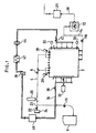
- Fig. 1 is a circuit diagram schematically illustrating an apparatus for sterilization according to one embodiment of the invention.
- a sterilizing chamber 2 which contains an article therein for sterilization, is connected through a gas pipe 4 to a hydrogen peroxide gas feeder 6.
- Valves 8 and 10 are disposed in the gas pipe 4 toward the chamber 2 and the feeder 6, respectively.
- a vacuum pump 12 operative to draw gas from the chamber 2, is connected to the chamber 2 through a suction pipe 14 and a valve 16. Gas drawn by the pump 12 is passed through a downstream discharge pipe 18 having a catalyst 20 disposed therein to be exhausted externally or outdoors.
- An air inlet 24 is connected to a point in the gas pipe 4 located between the pair of valves 8, 10 through another valve 22 and an extension pipe 23. Air admitted through the air inlet 24 is introduced into the chamber 2 through a sterilizing filter 26 which is connected in the gas pipe 4.
- a pressure gauge 28 and a thermometer 30 are mounted on the chamber 2 to detect the pressure and the temperature within the chamber.
- a concentration meter 32 is also mounted to determine the concentration of hydrogen peroxide gas in the chamber 2.
- a circulation path 34 is connected to the chamber 2 and forms a closed circuit together with the latter.
- a circulating fan 36 is connected in the circulation path 34, and valves 38 and 40 are also connected in the circulation path 34 at locations toward the outlet and the inlet, respectively, of the chamber 2. When the both valves 38 and 40 are open, the operation of the fan 36 allows gas in the chamber 2 to be circulated.
- a heater 42 which heats the circulating gas and a filter 44 are connected in the circulation path 34.
- a catalyst 46 is also disposed in the circulation path 34 to adsorp hydrogen peroxide gas contained in the air which circulates the path 34. In the present embodiment, platinum or palladium is used for the catalyst 46, whereby a simple passage of hydrogen peroxide therethrough enables a decomposition thereof in a facilitated manner.
- the valve 16 connected in the suction pipe 14 connected to the vacuum pump 12 is then opened, and the pump 12 is operated, thus drawing air from the chamber 2 to achieve a vacuum condition.
- a vacuum condition which corresponds to a given pressure is attained, the valve 16 associated with the pump 12 is closed while the valves 8 and 10 in the gas pipe 4 are opened to begin and continue supplying hydrogen peroxide gas from the feeder 6 into the chamber 2 until the entire article to be sterilized is immersed in the hydrogen peroxide gas.
- a chosen amount of hydrogen peroxide gas be supplied since when supplied in excess, the hydrogen peroxide no longer assumes a gas phase.
- the air pressure in the chamber 2 is greatly reduced as a result of operation of the vacuum pump 12, the hydrogen peroxide gas has a high level of partial pressure.
- the valve 22 associated with the air inlet 24 is opened to allow sterilized air, which is obtained by passage through the sterilizing filter 26, to be introduced into the chamber 2, raising the internal pressure thereof slightly above its initial vacuum condition. This condition is maintained for a few minutes, allowing the hydrogen peroxide gas to permeate into detailed features of the article. Sterilization is then continued by repeating a sequence of the suction step by the pump 12, the step of feed sterilizing gas and the step of introducing sterilized air several times.
- the degassing step to remove hydrogen peroxide gas from the chamber 2 takes place.
- the vacuum pump 12 is operated to reestablish a vacuum condition corresponding to a given pressure within the sterilizing chamber 2 by drawing gas therefrom.
- the valve 16 associated with the pump 12 is closed while the valve 22 associated with the air inlet 24 and the valve 8 disposed in the gas pipe 4 toward the chamber 2 are opened, thus introducing sterilized air into the chamber 2 and raising the pressure within the chamber to a level slightly below the atmospheric pressure.
- valves 22 and 8 are then closed while the valves 38 and 40 connected in the circulation path 34 toward the outlet and the inlet of the chamber 2 are opened, and the circulating fan 36 is operated.
- the gas mixture of the air and the hydrogen peroxide gas circulates through the path 34.
- the catalyst 46 such as platinum adsorps the hydrogen peroxide and the heating of the circulating gas by the heater 42 promotes the decomposition of the hydrogen peroxide gas, thus reducing the concentration of the hydrogen peroxide in the chamber 2.
- the concentration of the hydrogen peroxide will be significantly reduced.
- the decomposition and the removal of the hydrogen peroxide gas can be achieved in a reduced length of time.
- the sterilization is achieved by using hydrogen peroxide gas which is not toxic. Accordingly, there is no adverse influence upon human bodies and environment, and decomposition products from the sterilization are oxygen and water, which are harmless.
- valve 16 in the pipe 14 leading to the pump 12 as well as the valve 22 in the extension pipe 23 from the air inlet 224 and the valve 8 in the gas pipe may be opened while simultaneously operating the pump 12, thus continuously displacing gas through the chamber 2 while drawing the air through the air inlet 24.
- the access door of the chamber when placing or removing an article into or from the chamber 2, the access door of the chamber may be maintained fully open while the pump 12 is operated to displace gas, thus preventing any residue of hydrogen peroxide gas in the chamber 2 from flowing out of the chamber.
- articles which can be sterilized by the apparatus of the embodiment are not limited to resin containers such as injection syringe or eyedropper, but that the invention is applicable to a variety of articles.
- the invention is particularly preferred for use with articles which are not heat resistant, and a perfect sterilization is assured even for an article which has a complicated configuration.
Landscapes
- Health & Medical Sciences (AREA)
- Epidemiology (AREA)
- Life Sciences & Earth Sciences (AREA)
- Animal Behavior & Ethology (AREA)
- General Health & Medical Sciences (AREA)
- Public Health (AREA)
- Veterinary Medicine (AREA)
- Chemical & Material Sciences (AREA)
- Chemical Kinetics & Catalysis (AREA)
- General Chemical & Material Sciences (AREA)
- Apparatus For Disinfection Or Sterilisation (AREA)
Claims (7)
- Einrichtung zur Sterilisierung, die eine Sterilisierungskammer (2) aufwiest, in welcher ein Gegenstand aufgenommen werden kann, eine Zufuhrvorrichtung (6) für Wasserstoffperoxyd, die an die Kammer über ein Gasrohr (4) angeschlossen ist, eine Vakuumpumpe (12), die an die Kammer durch ein Saugrohr (14) angeschlossen ist, um aus dieser Gas abzuziehen, und einen Lufteinlass (24), der an die Kammer (2) über eine Filterkammer (26) angeschlossen ist, gekennzeichnet durch einen geschlossenen Umwälzungsweg (34), der an die Kammer (21) durch ein Auslassventil (38) und ein Einlassventil (40) angeschlossen ist, ein in dem geschlossenen Umwälzungsweg vorgesehenes Umwälzgebläse (36), und einen in dem geschlossenen Umwälzungsweg angeordneten Katalysator (46).
- Einrichtung nach Anspruch 1, bei welcher eine Heizvorrichtung (42) in dem Umwälzungsweg (34) vorgesehen ist.
- Einrichtung nach Anspruch 1 oder 2, bei welcher ein Filter (44) in dem Umwälzungsweg (34) vorgesehen ist.
- Verfahren zur Sterilisierung, mit den Schritten, eine Vakuumpumpe zum Abziehen von Gas von einer Sterilisierungskammer zu verwenden, die abgedichtet umschlossen ist, damit in ihr ein Gegenstand aufgenommen werden kann, Zuführen von Wasserstoffperoxydgas in die Sterilisierungskammer zur Sterilisierung, Wiederholen der Schritte des Abziehens von Gas und des Zuführens von Wasserstoffperoxydgas mehrfach, nachfolgendes Einlassen von sterilisierter Luft in die Kammer, gekennzeichnet durch Umwälzen von Gas in der Kammer mithilfe eines Umwälzgebläses, und durch einen geschlossenen Umwälzungsweg, der an die Kammer durch ein Einlassventil und ein Auslassventil angeschlossen ist, und Durchleiten des Gases durch einen Katalysator, der in dem Umwälzungsweg angeordnet ist, um das Wasserstoffperoxydgas zu entfernen.
- Verfahren nach Anspruch 4, bei welchem der Schritt der Zuführung von Wasserstoffperoxydgas in die Sterilisierungskammer zur Sterilisierung umfasst, nach dem Zuführen des Wasserstoffperoxydgases sterilisierte Luft in die Sterilisierungskammer einzulassen, wobei dieser Zustand über ein vorgegebenes Zeitintervall beibehalten wird.
- Verfahren nach Anspruch 4, welches folgend auf den Schritt des Entfernens des Wasserstoffperoxydgases umfasst, eine Saugwirkung auf die Sterilisierungskammer von der Vakuumpumpe aufzubringen, während Luft von einem Einlass in die Sterilisierungskammer eingelassen wird.
- Verfahren nach Anspruch 4, mit dem weiteren Schritt, die Vakuumpumpe dazu zu betreiben, dass Gas verdrängt wird, wenn ein Gegenstand in die Sterilisierungskammer eingebracht oder aus dieser entnommen wird.
Applications Claiming Priority (3)
| Application Number | Priority Date | Filing Date | Title |
|---|---|---|---|
| JP15585397A JP3783337B2 (ja) | 1997-05-29 | 1997-05-29 | 滅菌装置および滅菌方法 |
| JP155853/97 | 1997-05-29 | ||
| JP15585397 | 1997-05-29 |
Publications (3)
| Publication Number | Publication Date |
|---|---|
| EP0880972A2 EP0880972A2 (de) | 1998-12-02 |
| EP0880972A3 EP0880972A3 (de) | 1998-12-09 |
| EP0880972B1 true EP0880972B1 (de) | 2004-02-25 |
Family
ID=15614938
Family Applications (1)
| Application Number | Title | Priority Date | Filing Date |
|---|---|---|---|
| EP19980107826 Expired - Lifetime EP0880972B1 (de) | 1997-05-29 | 1998-04-29 | Vorrichtung und Verfahren zum Sterilisieren |
Country Status (3)
| Country | Link |
|---|---|
| EP (1) | EP0880972B1 (de) |
| JP (1) | JP3783337B2 (de) |
| DE (1) | DE69821825T2 (de) |
Cited By (1)
| Publication number | Priority date | Publication date | Assignee | Title |
|---|---|---|---|---|
| US10905786B2 (en) | 2017-03-27 | 2021-02-02 | Regeneron Pharmaceuticals, Inc. | Sterilisation method |
Families Citing this family (12)
| Publication number | Priority date | Publication date | Assignee | Title |
|---|---|---|---|---|
| GB2351664A (en) | 1999-06-04 | 2001-01-10 | Microflow Ltd | Sterilizing enclosures |
| JP4106814B2 (ja) * | 1999-06-18 | 2008-06-25 | 澁谷工業株式会社 | 滅菌装置 |
| GB2367494A (en) * | 2000-08-04 | 2002-04-10 | Microflow Ltd | Sterilizing enclosures using sterilant vapours |
| DE102004062368B3 (de) | 2004-12-13 | 2006-07-27 | Alfred Kärcher Gmbh & Co. Kg | Verfahren und Vorrichtung zum Entgiften oder Entseuchen von temperaturempfindlien Gegenständen, insbesondere von militärischem Kleingerät |
| JP5464845B2 (ja) * | 2008-11-28 | 2014-04-09 | 四国化工機株式会社 | 無菌エアー循環式食品充填包装機 |
| EP2666483B1 (de) * | 2008-12-31 | 2014-12-03 | American Sterilizer Company | Vorrichtung zur Beförderung eines Trägergases mit chemischer Substanz |
| JP5735761B2 (ja) * | 2010-07-26 | 2015-06-17 | 株式会社Ihi | 有毒物質の除染装置 |
| JP5605343B2 (ja) * | 2011-10-06 | 2014-10-15 | キヤノンマーケティングジャパン株式会社 | 滅菌装置および滅菌方法 |
| CN103405797B (zh) * | 2013-08-13 | 2016-03-16 | 老肯医疗科技股份有限公司 | 适用于内镜灭菌的过氧化氢低温灭菌设备及其使用方法 |
| JP6020498B2 (ja) * | 2014-03-24 | 2016-11-02 | キヤノンマーケティングジャパン株式会社 | 滅菌装置および滅菌方法 |
| JP6436295B2 (ja) * | 2014-10-24 | 2018-12-12 | 三浦工業株式会社 | 過酸化水素ガス滅菌装置 |
| CN106139199A (zh) * | 2015-04-24 | 2016-11-23 | 南通华尔康医疗科技股份有限公司 | 一种快速进行环氧乙烷解析的方法及装置 |
Family Cites Families (11)
| Publication number | Priority date | Publication date | Assignee | Title |
|---|---|---|---|---|
| JPS5570255A (en) * | 1978-11-21 | 1980-05-27 | Tomoe Shokai Kk | Method of removing remaining medicine and its device |
| JPS609456B2 (ja) * | 1981-02-18 | 1985-03-11 | 拓實 鹿川 | ガス滅菌器におけるガス抜き方法 |
| GB2127692A (en) * | 1982-09-29 | 1984-04-18 | American Sterilizer Co | Hydrogen peroxide liquid film sterilization method |
| CA1303811C (en) * | 1987-07-06 | 1992-06-23 | Robert W. Childers | Flow-through vapor phase sterilization system |
| US5229071A (en) * | 1988-08-19 | 1993-07-20 | Meo Iii Dominic | Catalytic oxidizer for treating fixed quantities of gases |
| JPH08271464A (ja) * | 1995-03-30 | 1996-10-18 | Taiyo Toyo Sanso Co Ltd | 過酸化水素蒸気の濃度検出方法及びその装置 |
| US5872359A (en) * | 1995-07-27 | 1999-02-16 | American Sterilizer Company | Real-time monitor and control system and method for hydrogen peroxide vapor decontamination |
| MY115198A (en) * | 1995-08-11 | 2003-04-30 | Nestle Sa | Process and apparatus for sterilising surfaces |
| JPH09108319A (ja) * | 1995-10-19 | 1997-04-28 | Zexel Corp | オゾン殺菌装置 |
| JPH09131390A (ja) * | 1995-11-09 | 1997-05-20 | Taiyo Toyo Sanso Co Ltd | ガス滅菌処理方法及びガス滅菌処理システム |
| GB9523717D0 (en) * | 1995-11-20 | 1996-01-24 | Mdh Ltd | Method and apparatus for hydrogen peroxide vapour sterilization |
-
1997
- 1997-05-29 JP JP15585397A patent/JP3783337B2/ja not_active Expired - Fee Related
-
1998
- 1998-04-29 EP EP19980107826 patent/EP0880972B1/de not_active Expired - Lifetime
- 1998-04-29 DE DE1998621825 patent/DE69821825T2/de not_active Expired - Lifetime
Cited By (2)
| Publication number | Priority date | Publication date | Assignee | Title |
|---|---|---|---|---|
| US10905786B2 (en) | 2017-03-27 | 2021-02-02 | Regeneron Pharmaceuticals, Inc. | Sterilisation method |
| US10918754B2 (en) | 2017-03-27 | 2021-02-16 | Regeneron Pharmaceuticals, Inc. | Sterilisation method |
Also Published As
| Publication number | Publication date |
|---|---|
| DE69821825D1 (de) | 2004-04-01 |
| EP0880972A3 (de) | 1998-12-09 |
| EP0880972A2 (de) | 1998-12-02 |
| JPH10328276A (ja) | 1998-12-15 |
| DE69821825T2 (de) | 2004-12-09 |
| JP3783337B2 (ja) | 2006-06-07 |
Similar Documents
| Publication | Publication Date | Title |
|---|---|---|
| EP0880972B1 (de) | Vorrichtung und Verfahren zum Sterilisieren | |
| US4517159A (en) | Sterilizer | |
| US4203943A (en) | Method of biocidal sterilization using cyclic subatmospheric pressure conditioning | |
| US9827341B2 (en) | Method for sterilising and sterilising device | |
| CA1232424A (en) | Sterilization method and apparatus using a gaseous agent | |
| JP4914971B2 (ja) | 容器を滅菌する方法 | |
| JPS649862B2 (de) | ||
| JPH11193010A (ja) | 医療用滅菌包装における滅菌方法 | |
| JP4218076B2 (ja) | 滅菌装置 | |
| WO1999026667A3 (de) | Dampfsterilisations- bzw. dampfdesinfektionsverfahren und vorrichtung zur durchführung des verfahrens | |
| KR101298730B1 (ko) | 플라즈마 멸균 방법 | |
| KR200412929Y1 (ko) | 절수형 고압증기 멸균기 | |
| EP0202366A2 (de) | Verfahren und Vorrichtung zur Sterilisation von Erzeugnissen | |
| JPH07136236A (ja) | オゾン混合蒸気滅菌方法及び装置 | |
| JP4160859B2 (ja) | プラズマ滅菌装置及びプラズマ滅菌方法 | |
| JP3099200B2 (ja) | 過酸化水素ガス供給装置の滅菌方法 | |
| JP5074330B2 (ja) | プレフィルドシリンジの除染方法 | |
| JPH0263461A (ja) | ガス滅菌器に於ける残留ガス除去方法 | |
| JPH0731664A (ja) | ガス滅菌器における滅菌ガス処理装置 | |
| CN109731109B (zh) | 一种塑料安瓿的输液制剂的制备系统及预处理方法 | |
| JP2001178798A (ja) | 蒸気滅菌器およびその運転方法 | |
| JP2002052073A (ja) | ガス滅菌器の運転方法 | |
| KR960002603A (ko) | 처리장치, 처리방법 및 처리장치의 크리닝 방법 | |
| JP2022044186A (ja) | 除染方法及び除染装置 | |
| JPH0546461Y2 (de) |
Legal Events
| Date | Code | Title | Description |
|---|---|---|---|
| PUAI | Public reference made under article 153(3) epc to a published international application that has entered the european phase |
Free format text: ORIGINAL CODE: 0009012 |
|
| PUAL | Search report despatched |
Free format text: ORIGINAL CODE: 0009013 |
|
| 17P | Request for examination filed |
Effective date: 19980429 |
|
| AK | Designated contracting states |
Kind code of ref document: A2 Designated state(s): CH DE FR GB LI |
|
| AX | Request for extension of the european patent |
Free format text: AL;LT;LV;MK;RO;SI |
|
| AK | Designated contracting states |
Kind code of ref document: A3 Designated state(s): AT BE CH CY DE DK ES FI FR GB GR IE IT LI LU MC NL PT SE |
|
| AX | Request for extension of the european patent |
Free format text: AL;LT;LV;MK;RO;SI |
|
| AKX | Designation fees paid |
Free format text: CH DE FR GB LI |
|
| 17Q | First examination report despatched |
Effective date: 20021119 |
|
| GRAP | Despatch of communication of intention to grant a patent |
Free format text: ORIGINAL CODE: EPIDOSNIGR1 |
|
| GRAS | Grant fee paid |
Free format text: ORIGINAL CODE: EPIDOSNIGR3 |
|
| GRAA | (expected) grant |
Free format text: ORIGINAL CODE: 0009210 |
|
| AK | Designated contracting states |
Kind code of ref document: B1 Designated state(s): CH DE FR GB LI |
|
| REG | Reference to a national code |
Ref country code: GB Ref legal event code: FG4D |
|
| REG | Reference to a national code |
Ref country code: CH Ref legal event code: EP |
|
| REG | Reference to a national code |
Ref country code: CH Ref legal event code: NV Representative=s name: NOVAGRAAF INTERNATIONAL SA |
|
| REF | Corresponds to: |
Ref document number: 69821825 Country of ref document: DE Date of ref document: 20040401 Kind code of ref document: P |
|
| ET | Fr: translation filed | ||
| PLBE | No opposition filed within time limit |
Free format text: ORIGINAL CODE: 0009261 |
|
| STAA | Information on the status of an ep patent application or granted ep patent |
Free format text: STATUS: NO OPPOSITION FILED WITHIN TIME LIMIT |
|
| 26N | No opposition filed |
Effective date: 20041126 |
|
| REG | Reference to a national code |
Ref country code: CH Ref legal event code: PFA Owner name: SHIBUYA KOGYO CO., LTD Free format text: SHIBUYA KOGYO CO., LTD#58, KOH, MAMEDAHONMACHI#KANAZAWA-SHI, ISHIKAWA-KEN (JP) -TRANSFER TO- SHIBUYA KOGYO CO., LTD#58, KOH, MAMEDAHONMACHI#KANAZAWA-SHI, ISHIKAWA-KEN (JP) |
|
| PGFP | Annual fee paid to national office [announced via postgrant information from national office to epo] |
Ref country code: DE Payment date: 20110427 Year of fee payment: 14 Ref country code: CH Payment date: 20110412 Year of fee payment: 14 Ref country code: FR Payment date: 20110426 Year of fee payment: 14 |
|
| PGFP | Annual fee paid to national office [announced via postgrant information from national office to epo] |
Ref country code: GB Payment date: 20110427 Year of fee payment: 14 |
|
| REG | Reference to a national code |
Ref country code: CH Ref legal event code: PL |
|
| GBPC | Gb: european patent ceased through non-payment of renewal fee |
Effective date: 20120429 |
|
| REG | Reference to a national code |
Ref country code: FR Ref legal event code: ST Effective date: 20121228 |
|
| PG25 | Lapsed in a contracting state [announced via postgrant information from national office to epo] |
Ref country code: GB Free format text: LAPSE BECAUSE OF NON-PAYMENT OF DUE FEES Effective date: 20120429 Ref country code: LI Free format text: LAPSE BECAUSE OF NON-PAYMENT OF DUE FEES Effective date: 20120430 Ref country code: CH Free format text: LAPSE BECAUSE OF NON-PAYMENT OF DUE FEES Effective date: 20120430 |
|
| REG | Reference to a national code |
Ref country code: DE Ref legal event code: R119 Ref document number: 69821825 Country of ref document: DE Effective date: 20121101 |
|
| PG25 | Lapsed in a contracting state [announced via postgrant information from national office to epo] |
Ref country code: FR Free format text: LAPSE BECAUSE OF NON-PAYMENT OF DUE FEES Effective date: 20120430 |
|
| PG25 | Lapsed in a contracting state [announced via postgrant information from national office to epo] |
Ref country code: DE Free format text: LAPSE BECAUSE OF NON-PAYMENT OF DUE FEES Effective date: 20121101 |