EP0879479B1 - Auftrennbare verbindungsbrücke (fuse) und verbindbare leitungsunterbrechung (anti-fuse), sowie verfahren zur herstellung und aktivierung einer fuse und einer anti-fuse - Google Patents
Auftrennbare verbindungsbrücke (fuse) und verbindbare leitungsunterbrechung (anti-fuse), sowie verfahren zur herstellung und aktivierung einer fuse und einer anti-fuse Download PDFInfo
- Publication number
- EP0879479B1 EP0879479B1 EP97914128A EP97914128A EP0879479B1 EP 0879479 B1 EP0879479 B1 EP 0879479B1 EP 97914128 A EP97914128 A EP 97914128A EP 97914128 A EP97914128 A EP 97914128A EP 0879479 B1 EP0879479 B1 EP 0879479B1
- Authority
- EP
- European Patent Office
- Prior art keywords
- conduction
- fuse
- track
- substrate
- semiconductor material
- Prior art date
- Legal status (The legal status is an assumption and is not a legal conclusion. Google has not performed a legal analysis and makes no representation as to the accuracy of the status listed.)
- Expired - Lifetime
Links
Images

Classifications
-
- H—ELECTRICITY
- H01—ELECTRIC ELEMENTS
- H01L—SEMICONDUCTOR DEVICES NOT COVERED BY CLASS H10
- H01L23/00—Details of semiconductor or other solid state devices
- H01L23/52—Arrangements for conducting electric current within the device in operation from one component to another, i.e. interconnections, e.g. wires, lead frames
- H01L23/522—Arrangements for conducting electric current within the device in operation from one component to another, i.e. interconnections, e.g. wires, lead frames including external interconnections consisting of a multilayer structure of conductive and insulating layers inseparably formed on the semiconductor body
- H01L23/525—Arrangements for conducting electric current within the device in operation from one component to another, i.e. interconnections, e.g. wires, lead frames including external interconnections consisting of a multilayer structure of conductive and insulating layers inseparably formed on the semiconductor body with adaptable interconnections
- H01L23/5256—Arrangements for conducting electric current within the device in operation from one component to another, i.e. interconnections, e.g. wires, lead frames including external interconnections consisting of a multilayer structure of conductive and insulating layers inseparably formed on the semiconductor body with adaptable interconnections comprising fuses, i.e. connections having their state changed from conductive to non-conductive
-
- H—ELECTRICITY
- H01—ELECTRIC ELEMENTS
- H01L—SEMICONDUCTOR DEVICES NOT COVERED BY CLASS H10
- H01L23/00—Details of semiconductor or other solid state devices
- H01L23/52—Arrangements for conducting electric current within the device in operation from one component to another, i.e. interconnections, e.g. wires, lead frames
- H01L23/535—Arrangements for conducting electric current within the device in operation from one component to another, i.e. interconnections, e.g. wires, lead frames including internal interconnections, e.g. cross-under constructions
-
- H—ELECTRICITY
- H01—ELECTRIC ELEMENTS
- H01L—SEMICONDUCTOR DEVICES NOT COVERED BY CLASS H10
- H01L2924/00—Indexing scheme for arrangements or methods for connecting or disconnecting semiconductor or solid-state bodies as covered by H01L24/00
- H01L2924/0001—Technical content checked by a classifier
- H01L2924/0002—Not covered by any one of groups H01L24/00, H01L24/00 and H01L2224/00
-
- H—ELECTRICITY
- H01—ELECTRIC ELEMENTS
- H01L—SEMICONDUCTOR DEVICES NOT COVERED BY CLASS H10
- H01L2924/00—Indexing scheme for arrangements or methods for connecting or disconnecting semiconductor or solid-state bodies as covered by H01L24/00
- H01L2924/30—Technical effects
- H01L2924/301—Electrical effects
- H01L2924/3011—Impedance
Definitions
- the invention relates to a separable connecting bridge and a connectable line break, as well a method of making and activating a separable Connection bridge and a connectable line break.
- Fuse arrangements are used in integrated circuits, to be electrical after the actual manufacturing process Disconnect conductive connections ("fuse") or create new ones ( "Anti-fuse”).
- the use of such fuse arrangements are very diverse. So fuses become trimming used for example by analog circuits. Farther fuses are used to activate redundant circuit parts and switch off faulty ones.
- PLA programmable Logic arrays
- Essential criteria for fuse or anti-fuse arrangements are durability and reliability, i.e. how safe and over what period of time a fuse or anti-fuse the two states Preserved off / on, regardless of current density and temperature. Another criterion is the effort to activate fuse or Anti-fuse arrangements, for example when testing a fuse. For security-critical Applications is still security against reprogramming and external contact essential.
- fuse assemblies made of metal, made of polysilicon, or of a dielectric.
- the poly fuses to be assigned to another class are shown in same type as metal fuses as laser fuses or electrical ones Fuses executed.
- As an electrical fuse the conductive Material poly-silicon compared to metal disadvantages because due to the relatively good thermal coupling to the substrate and the better migration resistance the thermal destruction making the fuse more difficult to activate.
- the third-class anti-fuses with one Dielectric for example from the material SiN, see M. T. Takagi, I. Yoshii, N. Ikeda, H. Yasuda, K. Hama, Pros. IEDM 1993, pages 31 to 34
- a high-resistance semiconductor e.g. from amorphous silicon, see K.E. Gordon, R. J. Wong, Proc. IEDM 1993, pages 27 to 30
- destructible Isolators are typically used with programmable logic arrays used. They are caused by sufficiently high voltages activated. Protection against manipulation is opposite Improved metal and polyfuses. Nevertheless, there is locally high current densities in the programmed (conductive) Anti-fuses the danger of the insulation healing again. On Another major disadvantage of such anti-fuses is the higher Process expenditure for the additional insulator and electrode layers.
- an anti-fuse arrangement with a P + -doped diffusion region formed within an N-well and an aluminum conductor track assigned to the diffusion region has also become known.
- This anti-fuse arrangement is activated by applying a sufficiently large current to the conductor track so that aluminum migrates downward from the conductor track into the diffusion region, and irreversible conduction is caused by destruction of the pn junction of the diffusion region.
- This anti-fuse arrangement initially only represents a one-sided anti-fuse arrangement, ie it can only be operated in one current direction, ie it acts as a diode switched in the reverse direction.
- the invention is based, an easy to manufacture the task and fuse and / or anti-fuse arrangement to be activated to make available, which in safety-relevant integrated circuits can be applied.
- the invention provides for the formation of a new class or of a new type of fuse and anti-fuse arrangement those instead of one applied to the substrate and therefore easily recognizable metal sheet one within the surface of the semiconductor substrate, not from the outside recognizable conductive diffusion path is formed, which for Activation is separated or established.
- the semiconductor material of the substrate represents a first conductivity type, while the material of the diffusion connection from a second Line type is the opposite of the first line type Has a sign.
- the fuse or anti-fuse arrangement may be the first conduction type be referred to as p and the second conduction type as n, where however, it is within the scope of the invention, the two line types to swap.
- fuse and anti-fuse arrangements alone with conductive To form diffusion regions in a semiconductor substrate; any metal tracks are not required.
- the fuse and anti-fuse arrangements according to the invention external contact cannot be found is extremely complicated, and reprogramming impossible, so that the fuse and anti-fuse arrangements according to the invention ideally suited for safety circuits.
- the fuse and anti-fuse arrangements according to the invention have inherently high reliability because of the activation the fuse or anti-fuse diffusion process to be carried out is thermodynamically irreversible, so that one time In principle, activated fuse or anti-fuse do not heal again can.
- a heating of the activation section by the insert a laser is basically also a means of heating a current flow through the diffusion path possible.
- a resistive heating preferably made of polysilicon manufactured resistance meanders that in immediate Neighborhood to the activation section integrated on the Semiconductor substrate can be formed.
- the separable connecting bridge (fuse) has one in a made of semiconductor material of a first Conductivity type existing substrate trained electrically conductive, continuous in the longitudinal direction, transverse to the longitudinal extent having a predetermined width Diffusion or conduction path of a second, from the first Conductivity type of opposite conduction type, the semiconductor material such a concentration of the first conduction type compared to the material of the conduit that at a predetermined activation temperature, the greater is over as the operating temperature of the connecting bridge the entire width of the conduit is interrupted Diffusion of the dopant of the semiconductor material of the first conductivity type he follows.
- the conduit is one in the substrate formed from semiconductor material Diffusion area is assigned, which by doping with a Dopant of the first conductivity type is formed.
- the connecting bridge according to the invention can be provided that by doping diffusion region formed with the dopant of the first line type on both sides of the opposite of the Dimensions of the diffusion area have a smaller width Track of the second conduction type is formed is. It is advantageously provided that the conduit of the second conductivity type by doping with a doping element is formed, the doping concentration in terms of amount less than the doping concentration of the dopant Diffusion range of the first conductivity type.
- the connectable line interruption (anti-fuse) has one in a semiconductor material Substrate formed electrically conductive, by doping diffusion or conduction path formed with a dopant with in the longitudinal extent a gap with a predetermined Distance-forming sections of a first type of line and at least the area of the gap of the conductor track pieces filling, diffusion area of a second, of the first line type of the opposite line type on, wherein the dopant of the conductor track pieces at a predetermined Diffusion constant with respect to the semiconductor material of the substrate has such a doping concentration that at a predetermined activation temperature, the greater is as the operating temperature of the line break, Diffusion over the entire distance of the gap in the conductor track of the dopant of the conductor track pieces takes place and to an electrical connection of the two conduction pieces leads.
- the diffusion region of the second conductivity type by doping with a doping element is formed, the doping concentration in terms of amount less than the doping concentration of the dopant Line sections of the first line type is.
- the line break according to the invention is distinguished is characterized in that by the pieces of conduction and the diffusion area filling the gap of the conductor track pieces an activation section with at least two p-n transition is formed.
- the anti-fuse according to the invention a two-sided, real anti-fuse in represent two current directions.
- the practical impossible analyzability and thus the external contactability of the connecting bridge according to the invention which can hardly be carried out and which remains protected by passivation layers.
- at least the activation section consisting of part of the conductor track and the semiconductor material and / or the diffusion region is covered with an electrically insulating covering layer formed on the main surface of the substrate and transparent or at least translucent for radiation of a predetermined wavelength for local heating of the activation section is.
- Typical fuse lasers e.g. neodymium YAG lasers
- penetrate this transparent or at least translucent covering layer such as made of oxide or Si 3 N 4 largely unhindered and deposit the radiation energy predominantly in silicon, i.e. in the material of the diffusion sheet or the substrate.
- the invention even one within the semiconductor substrate provide buried arrangement of fuse or anti-fuse, so that an outside location and external contacting is even more difficult. It is provided that the Diffusion or conduction path completely within the Semiconductor material existing in an outgoing from the main surface of the substrate predetermined depth is arranged or formed.
- the method can be provided for local heating the activation section a radiation with a predetermined wavelength is used.
- Radiation from a laser light source can be used.
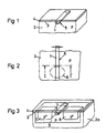
- Figures 1 and 2 show the basic structure of a lateral diffusion fuse arrangement according to an embodiment of the invention with a low n-doped, narrow flat diffusion path with a width m of about 0.5 to 1 micron, which is of a large, p- doped area 2 is surrounded.
- Region 2 can represent the substrate of a wafer with the basic material silicon, which is already predoped by basic doping with, for example, boron in a concentration of approximately 3 ⁇ 10 15 cm -3 .
- the diffusion path is produced by implantation of arsenic with an energy of 120 KeV and a dose of approximately 5.0 • 10 14 cm -2 .
- the main surface 31 of the substrate is coated in a manner known per se with a photoresist with an exemplary thickness of approximately 1.5 ⁇ m, exposed and developed using a suitable mask.
- the photoresist is removed, for example, in an oxygen-containing plasma environment.
- the implantation of the diffusion path is followed by a healing step at a temperature of approximately 900 ° Celsius and a duration of 20 minutes. on.
- a covering layer 4 which is transparent or at least translucent for radiation of a predetermined wavelength can then be deposited on the main surface 31.
- an activation section 6 indicated by dashed lines is locally heated, for example by brief exposure to laser light of a suitable wavelength, so that in the area of the activation section 6 n-dopants diffuse into one another from the diffusion path and p-dopants the p-doped region 2 takes place. If the concentration of the p-doping of the region 2 is sufficiently high, the region of the activation section 6 is doped with high resistance, which leads to the interruption of the n-doped diffusion path.
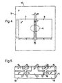
- FIGS. 3 and 4 show a fuse arrangement in accordance with a further exemplary embodiment of the invention.
- the reference numerals 1 and 3 to 6 here designate the same components as in the exemplary embodiment according to FIGS. 1 and 2.
- the diffusion path is assigned on both sides in the p + -doped diffusion regions 7, 8 formed in the substrate consisting of semiconductor material such as silicon, which are formed by implantation of, for example, boron at an energy of 20 KeV and a dose of about 5.0 ⁇ 10 15 cm -2 , and, relative to the main surface 31 of the substrate, have larger dimensions s, t than the width m of the diffusion path can.
- the two diffusion regions 7 and 8 are arranged at a distance r from one another.
- the diffusion regions 7, 8 are formed in a p-well 9 in the silicon substrate, which after structuring with conventional photolithography process steps using a mask 10 and subsequent implantation with boron at an energy of approximately 230 KeV and a dose of approximately 1.0 ⁇ 10 13 cm -2 can be formed.
- FIG. 5 shows a further exemplary embodiment of a fuse arrangement 5 according to the invention with two connection bridges 12 and 13 with n-doped diffusion tracks 14 which are formed side by side within the substrate or an n-well 11 and vertically formed with respect to the main surface 31 15 and 16 connected to one another by means of thin, vertically running n-doped channels 17 and 18.
- two n + -doped and thus low-resistance contact regions 19 and 20 are provided, which are produced by a suitable photolithography process step and a suitable implantation step.
- a further p + -doped contact region 21 formed in the main surface 31 allows the p + -doped diffusion region 22 to be completely contacted within the substrate or the n-well 11.
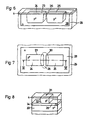
- FIGS. 6 and 7 show schematic views of the basic structure of a lateral diffusion anti-fuse arrangement according to a further exemplary embodiment of the invention.
- the substrate has silicon as the basic material with a p-type basic doping with boron of, for example, 3 • 10 15 cm -3 .
- the n-well 28 formed here can be formed after structuring with conventional photolithography process steps and subsequent implantation with phosphorus at an energy of approximately 460 KeV and a dose of approximately 6.0 ⁇ 10 12 cm -2 , an optional anti-punch implantation being used with arsenic at an energy of 320 KeV and a dose of about 8.0 • 10 11 cm -2 .
- the conduction path pieces 24 and 25 formed within the n-well 28 are exposed and developed using a suitable mask, via a subsequent implantation with boron at an energy of about 20 KeV and a dose of about 5.0 • 10 15 cm -2 .
- the conductor track pieces 24 and 25 are healed at a temperature of approximately 900 ° C. and a duration of approximately 20 minutes.
- the dimensions and doping concentrations of the conductor track pieces, 24, 25, the gap 26, and the surrounding diffusion region 27 are selected such that at a sufficiently high activation temperature, which is greater than the normal operating temperature of the line break or the other integrated circuits formed on the substrate , a thermodynamically irreversible diffusion of the dopants of the conductor track pieces 24, 25, 32, 33 takes place over the entire distance of the gap 26 of the conductor track pieces 24 and 25.
- FIG. 8 shows a further exemplary embodiment of the invention with a vertically arranged diffusion anti-fuse arrangement 31 with two highly p + -doped layers 32 and 33, which are isolated from one another by a thin n-doped layer 34.
- the p + -doped layers 32 and 33 forming the two conductor track pieces of the anti-fuse arrangement 31 with the n-doped layer 34 arranged therebetween, which represent the gap 26 between the conductor track pieces, can be produced with implantation steps or epitaxial steps.
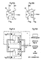
- Figure 9 shows an example of the multiple applications of fuse or anti-fuse arrangements according to the invention a wiring field with a variety of integrated trained Circuit groups 35, which are shown only schematically by the Diffusion anti-fuses 36 represented by double arrows are connectable. Are shown in an exemplary form two possible wiring paths 37 and 38.
- FIGS. 10A and 10B show a further preferred application example in the form of a programmable NAND gate 39 and a programmable NOR gate 40 with diffusion anti-fuse arrangements a, b, c, d, e, and f schematically represented by broken lines.
- This exemplary embodiment is particularly suitable for subsequent test circuit modifications in which, by activating the anti-fuse arrangements a, b, c or d, e, f and correspondingly connecting the MOS transistors T or coupling them to a supply voltage V DD and a ground V SS a NAND or NOR function with inputs E1, E2 and an output Off can be implemented.
- FIG. 11A shows the layout representation in a schematic plan view such programmable NAND-NOR gates 39 and 40, 11B explains the symbols of the individual layers is.
Description
- Vorsehen eines aus Halbleitermaterial eines ersten Leitungstyps bestehenden Substrates,
- Ausbilden einer elektrisch leitenden, in Längserstreckung kontinuierlich durchgehenden, quer zur Längserstreckung eine vorbestimmte Breite aufweisenden Leitungsbahn eines zweiten, vom ersten Leitungstyp entgegengesetzten Leitungstyps in dem aus Halbleitermaterial bestehenden Substrat, und
- Erwärmen eines die Leitungsbahn und wenigstens einen Teil des Halbleitermaterials des Substrates umfassenden Aktivierungsabschnittes bis zu einer vorbestimmten Aktivierungstemperatur, die größer ist als die Betriebstemperatur der Verbindungsbrücke, zur irreversiblen Unterbrechung über die gesamte Breite der Leitungsbahn durch Diffusion des Dotierstoffes des Halbleitermaterials des ersten Leitungstyps.
- Ausbilden einer elektrisch leitenden Leitungsbahn durch Dotierung mit einem Dotierstoff mit in Längserstreckung eine Lücke mit einem vorbestimmten Abstand bildenden Leitungsbahnstücken eines ersten Leitungstyps in einem aus Halbleitermaterial eines zweiten, vom ersten Leitungstyp entgegengesetzten Leitungstyps bestehenden Substrat, und
- Erwärmen eines die Lücke der Leitungsbahnstücke umfassenden Aktivierungsabschnittes bis zu einer vorbestimmten Aktivierungstemperatur, die größer ist als die Betriebstemperatur der Leitungsunterbrechung, zur irreversiblen Diffusion des Dotierstoffes der Leitungsbahnstücke über die gesamte Lücke der Leitungsbahn.
- Figur 1
- eine schematische Ansicht einer auftrennbaren Verbindungsbrücke (Fuse) gemäß einem Ausführungsbeispiel der Erfindung;
- Figur 2
- eine schematische Draufsicht der Fuse-Anordnung gemäß dem Ausführungsbeispiel nach Figur 1;
- Figur 3
- eine schematische Ansicht einer auftrennbaren Verbindungsbrücke (Fuse) gemäß einem weiteren Ausführungsbeispiel der Erfindung;
- Figur 4
- eine schematische Draufsicht der Fuse-Anordnung gemäß einem weiteren Ausführungsbeispiel nach Figur 1;
- Figur 5
- eine schematische Ansicht einer vertikalen Diffusions-Fuse-Anordnung gemäß einem weiteren Ausführungsbeispiel der Erfindung;
- Figur 6
- eine schematische Darstellung einer Diffusions-Anti-Fuse-Anordnung gemäß einem Ausführungsbeispiel der Erfindung;
- Figur 7
- eine schematische Draufsicht der Anti-Fuse-Anordnung gemäß dem Ausführungsbeispiel nach Figur 6;
- Figur 8
- eine schematische Darstellung einer vertikalen Diffusions-Anti-Fuse-Anordnung gemäß einem weiteren Ausführungsbeispiel der Erfindung;
- Figur 9
- eine schematische Draufsicht eines Verdrahtungsfeldes mit Diffusions-Anti-Fuseanordnungen gemäß einem Anwendungs beispiel der Erfindung;
- Figur 10A und 10B
- Schaltbilder eines programmierbaren NAND-Gatters und NOR-Gatters mit Diffusions-Anti-Fuseanordnungen gemäß einem weiteren Anwendungs beispiel der Erfindung; und
- Figur 11A und 11B
- eine schematische Draufsicht eines Lay-out-Beispieles des Anwendungs beispieles nach den Figuren 10A und 10B.
Claims (20)
- Auftrennbare Verbindungsbrücke (Fuse) (5,12,13) mit einer in einem aus Halbleitermaterial eines ersten Leitungstyps bestehenden Substrat (2,9) ausgebildeten elektrisch leitenden, in Längserstrekkung kontinuierlich durchgehenden, quer zur Längserstreckung eine vorbestimmte Breite (m) aufweisenden Leitungsbahn (1,14) eines zweiten, vom ersten Leitungstyp entgegengesetzten Leitungstyps, wobei das Halbleitermaterial des ersten Leitungstyps eine ausreichend hohe Dotierkonzentration gegenüber dem Material der Leitungsbahn aufweist, so daß bei einer vorbestimmten Aktivierungstemperatur, die größer ist als die Betriebstemperatur der Verbindungsbrücke, über die gesamte Breite (m) der Leitungsbahn eine Unterbrechung durch Diffusion des Dotierstoffes des Halbleitermaterials des ersten Leitungstyps erfolgt.
- Verbindungsbrücke nach Anspruch 1, dadurch gekennzeichnet, daß der Leitungsbahn ein in dem aus Halbleitermaterial bestehenden Substrat ausgebildeter Diffusionsbereich (7, 8) zugeordnet ist, der durch Dotierung mit einem Dotierstoff des ersten Leitungstyps ausgebildet ist.
- Verbindungsbrücke nach Anspruch 2, dadurch gekennzeichnet, daß der durch Dotierung mit dem Dotierstoff ausgebildete Diffusionsbereich (7, 8) des ersten Leitungstyps zu beiden Seiten der gegenüber den Abmessungen des Diffusionsbereiches (7, 8) eine geringere Breite (m) besitzenden Leitungsbahn des zweiten Leitungstyps ausgebildet ist.
- Verbindungsbrücke nach Anspruch 2 oder 3, dadurch gekennzeichnet, daß die Leitungsbahn des zweiten Leitungstyps durch. Dotierung mit einem Dotierelement ausgebildet ist, dessen Dotierkonzentration betragsmäßig kleiner als die Dotierkonzentration des Dotierstoffes des Diffusionsbereiches (7, 8) des ersten Leitungstyps ist.
- Verbindungsbrücke nach Anspruch 1 bis 4, dadurch gekennzeichnet, daß ein aus einem Teil der Leitungsbahn (1,14) und dem Halbleitermaterial (2,9) und/oder dem Diffusionsbereich (7, 8) bestehender Aktivierungsabschnitt (6) mit einer auf einer Hauptfläche (31) des Substrates ausgebildeten elektrisch isolierenden, für Strahlung einer vorbestimmten Wellenlänge zur lokalen Erwärmung des Aktivierungsabschnittes (6) transparenten oder wenigstens durchscheinenden Abdeckschicht (4) überdeckt ist.
- Verbindungsbrücke nach Anspruch 1 bis 5, dadurch gekennzeichnet, daß die Leitungsbahn (14) des zweiten Leitungstyps vollständig innerhalb des aus Halbleitermaterial bestehenden Substrates in einer ausgehend von der Hauptoberfläche (31) des Substrates vorbestimmten Tiefe angeordnet bzw. ausgebildet ist.
- Verbindungsbrücke nach Anspruch 6, dadurch gekennzeichnet, daß die innerhalb des Substrates ausgebildete Leitungsbahn (14) in ihrer Längserstreckung im wesentlichen quer zur Hauptoberfläche (31) des Substrates verläuft.
- Verbindungsbrücke nach Anspruch 1 bis 7, dadurch gekennzeichnet, daß die Leitungsbahn durch geeignete Dotierung als Widerstandsbahn ausgebildet ist, welche nach Beaufschlagung durch einen elektrischen Strom zur Aktivierung der Verbindungsbrücke erwärmbar ist.
- Verbindbare Leitungsunterbrechung (Antifuse) mit einer in einem aus Halbleitermaterial bestehenden Substrat ausgebildeten elektrisch leitenden, durch Dotierung mit einem Dotierstoff ausgebildeten Leitungsbahn (23), mit in Längserstreckung eine Lücke (26) mit einem vorbestimmten Abstand bildenden Leitungsbahnstücken (24, 25, 32, 33) eines ersten Leitungstyps und einem wenigstens den Bereich der Lücke (26) der Leitungsbahnstücke (24, 25, 32, 33) ausfüllenden Diffusionsbereich (28,34) eines zweiten, vom ersten Leitungstyp entgegengesetzten Leitungstyps, wobei der Dotierstoff der Leitungsbahnstücke (24, 25, 32, 33) bei vorgegebener Diffusionskonstante bezüglich des Halbleitermaterials des Substrates (29) eine ausreichend hohe Dotierkonzentration aufweist, so daß bei einer vorbestimmten Aktivierungstemperatur, die größer ist als die Betriebstemperatur der Leitungsunterbrechung, über den gesamten Abstand der Lücke (26) der Leiterbahn eine Diffusion des Dotierstoffes der Leitungsbahnstücke (24, 25, 32, 33) erfolgt und zu einer elektrischen Verbindung der beiden Leitungsbahnstücke (24, 25, 32, 33) führt.
- Leitungsunterbrechung nach Anspruch 9, dadurch gekennzeichnet, daß der Diffusionsbereich (28,34) des zweiten Leitungstyps durch Detierung mit einem Dotierelement ausgebildet ist, dessen Dotierkonzentration betragsmäßig kleiner als die Dotierkonzentration des Dotierstoffes der Leitungsbahnstücke (24, 25, 32, 33) des ersten Leitungstyps ist.
- Leitungsunterbrechung nach Anspruch 10, dadurch gekennzeichnet, daß die Leitungsbahnstücke (24, 25, 32, 33) und der Diffusionsbereich (28,34) mit einer auf einer Hauptfläche (31) des Substrates (29) ausgebildeten elektrisch isolierenden, für Strahlung einer vorbestimmten Wellenlänge zur lokalen Erwärmung eines die Lücke umfassenden Aktivierungsabschnittes (30) transparenten oder wenigstens durchscheinenden Abdeckschicht (4) überdeckt ist.
- Leitungsunterbrechung nach Anspruch 11, dadurch gekennzeichnet, daß wenigstens ein Teil der Leitungsbahnstücke (24, 25, 32, 33) innerhalb des aus Halbleitermaterial bestehenden Substrates in einer ausgehend von der Hauptoberfläche (31) des Substrates vorbestimmten Tiefe angeordnet bzw. ausgebildet ist.
- Leitungsunterbrechung nach Anspruch 12, dadurch gekennzeichnet, daß wenigstens der innerhalb des Substrates ausgebildete Teil der Leitungsbahnstücke (24, 25, 32, 33) in seiner Längserstreckung im wesentlichen quer zur Hauptoberfläche (31) des Substrates verläuft.
- Verbindungsbrücke bzw. Leitungsunterbrechung nach Anspruch 1 bis 13, dadurch gekennzeichnet, daß sich die Leitungsbahn (23) in thermischen Kontakt mit einem Heizelement befindet.
- Verfahren zur Herstellung und Aktivierung einer auftrennbaren Verbindungsbrücke (Fuse) (5,12,13) gemäß Anspruch 1 mit den Schritten:Vorsehen eines aus Halbleitermaterial (2,9) eines ersten Leitungstyps bestehenden Substrates,Ausbilden einer elektrisch leitenden, in Längserstreckung kontinuierlich durchgehenden, quer zur Längserstreckung eine vorbestimmte Breite (m) aufweisenden Leitungsbahn (1,14) eines zweiten, vom ersten Leitungstyp entgegengesetzten Leitungstyps in dem aus Halbleitermaterial bestehenden Substrat, undErwärmen eines die Leitungsbahn (1,14) und wenigstens einen Teil des Halbleitermaterials des Substrates umfassenden Aktivierungsabschnittes (6) bis zu einer vorbestimmten Aktivierungstemperatur, die größer ist als die Betriebstemperatur der Verbindungsbrücke (5, 12, 13), zur irreversiblen Unterbrechung über die gesamte Breite der Leitungsbahn durch Diffusion des Dotierstoffes des Halbleitermaterials des ersten Leitungstyps.
- Verfahren nach Anspruch 15, dadurch gekennzeichnet, daß zur Erwärmung des Aktivierungsabschnittes (30) die durch geeignete Dotierung als Widerstandsbahn ausgebildete Leitungsbahn mit einem Heizstrom beaufschlagt wird.
- Verfahren zur Herstellung und Aktivierung einer verbindbaren Leitungsunterbrechung (Antifuse) gemäß Anspruch 9 mit den Schritten:Ausbilden einer elektrisch leitenden Leitungsbahn (23) durch Dotierung mit einem Dotierstoff mit in Längserstreckung eine Lücke (26) mit einem vorbestimmten Abstand bildenden Leitungsbahnstücken (24, 25, 32, 33) eines ersten Leitungstyps in einem aus Halbleitermaterial eines zweiten, vom ersten Leitungstyp entgegengesetzten Leitungstyps bestehenden Substrat, undErwärmen eines die Lücke (26) der Leitungsbahnstücke (24, 25, 32, 33) umfassenden Aktivierungsabschnittes (30) bis zu einer vorbestimmten Aktivierungstemperatur, die größer ist als die Betriebstemperatur der Leitungsunterbrechung, zur irreversiblen Diffusion des Dotierstoffes der Leitungsbahnstükke (24, 25, 32, 33) über die gesamte Lücke (26) der Leitungsbahn (23) und zum dauerhaften elektrischen Verbinden der Leitungsbahn stücke.
- Verfahren nach Anspruch 15 bis 17, dadurch gekennzeichnet, daß zur lokalen Erwärmung des Aktivierungsabschnittes (30) eine Strahlung mit einer vorbestimmten Wellenlänge verwendet wird.
- Verfahren nach Anspruch 18, dadurch gekennzeichnet, daß zur lokalen Erwärmung des Aktivierungsabschnittes (30) die Strahlung einer Laserlichtquelle verwendet wird.
- Verfahren nach Anspruch 15 bis 19, dadurch gekennzeichnet, daß zur Erwärmung des Aktivierungsabschnittes (30) ein in thermischen Kontakt mit der Leitungsbahn stehendes Heizelement verwendet wird.
Applications Claiming Priority (3)
| Application Number | Priority Date | Filing Date | Title |
|---|---|---|---|
| DE19604776A DE19604776A1 (de) | 1996-02-09 | 1996-02-09 | Auftrennbare Verbindungsbrücke (Fuse) und verbindbare Leitungsunterbrechung (Anti-Fuse), sowie Verfahren zur Herstellung und Aktivierung einer Fuse und einer Anti-Fuse |
| DE19604776 | 1996-02-09 | ||
| PCT/DE1997/000235 WO1997029515A2 (de) | 1996-02-09 | 1997-02-06 | Auftrennbare verbindungsbrücke (fuse) und verbindbare leitungsunterbrechung (anti-fuse), sowie verfahren zur herstellung und aktivierung einer fuse und einer anti-fuse |
Publications (2)
| Publication Number | Publication Date |
|---|---|
| EP0879479A2 EP0879479A2 (de) | 1998-11-25 |
| EP0879479B1 true EP0879479B1 (de) | 2003-05-02 |
Family
ID=7784979
Family Applications (1)
| Application Number | Title | Priority Date | Filing Date |
|---|---|---|---|
| EP97914128A Expired - Lifetime EP0879479B1 (de) | 1996-02-09 | 1997-02-06 | Auftrennbare verbindungsbrücke (fuse) und verbindbare leitungsunterbrechung (anti-fuse), sowie verfahren zur herstellung und aktivierung einer fuse und einer anti-fuse |
Country Status (10)
| Country | Link |
|---|---|
| EP (1) | EP0879479B1 (de) |
| JP (1) | JP3288385B2 (de) |
| KR (1) | KR100414239B1 (de) |
| CN (1) | CN1211856C (de) |
| AT (1) | ATE239302T1 (de) |
| DE (2) | DE19604776A1 (de) |
| ES (2) | ES2158310T3 (de) |
| IN (1) | IN191121B (de) |
| UA (1) | UA50755C2 (de) |
| WO (1) | WO1997029515A2 (de) |
Families Citing this family (6)
| Publication number | Priority date | Publication date | Assignee | Title |
|---|---|---|---|---|
| EP0992809A1 (de) | 1998-09-28 | 2000-04-12 | Siemens Aktiengesellschaft | Schaltungsanordnung mit deaktivierbarem Scanpfad |
| DE10346460A1 (de) * | 2003-10-02 | 2005-05-19 | Infineon Technologies Ag | Anordnung und Verfahren zum Schutz von Fuses/Anti-Fuses |
| DE10349749B3 (de) * | 2003-10-23 | 2005-05-25 | Infineon Technologies Ag | Anti-Fuse-Verbindung für integrierte Schaltungen sowie Verfahren zur Herstellung von Anti-Fuse-Verbindungen |
| JP4701034B2 (ja) * | 2005-08-02 | 2011-06-15 | パナソニック株式会社 | 半導体装置 |
| US7576407B2 (en) | 2006-04-26 | 2009-08-18 | Samsung Electronics Co., Ltd. | Devices and methods for constructing electrically programmable integrated fuses for low power applications |
| US8542517B2 (en) | 2011-06-13 | 2013-09-24 | International Business Machines Corporation | Low voltage programmable mosfet antifuse with body contact for diffusion heating |
Family Cites Families (7)
| Publication number | Priority date | Publication date | Assignee | Title |
|---|---|---|---|---|
| IT1131790B (it) * | 1979-08-20 | 1986-06-25 | Rca Corp | Complesso universale di collegamento interno per circuiti integrati cmos/sos ad alta densita' |
| EP0054102A3 (de) * | 1980-12-11 | 1983-07-27 | Rockwell International Corporation | ROM-Zellen in sehr dichter Anordnung und Herstellungsverfahren |
| GB2100057A (en) * | 1981-05-27 | 1982-12-15 | Post Office | Method of forming conductive tracks in a semi-conductor body by annealing |
| EP0094073B1 (de) * | 1982-05-12 | 1988-07-27 | Kabushiki Kaisha Toshiba | Halbleiteranordnung mit der Fähigkeit für strukturelle Selektion |
| GB2215128B (en) * | 1988-02-23 | 1991-10-16 | Stc Plc | Improvements in integrated circuits |
| JPH0320063A (ja) * | 1989-06-16 | 1991-01-29 | Matsushita Electron Corp | 電気ヒューズ |
| FR2713398B1 (fr) * | 1993-11-30 | 1996-01-19 | Sgs Thomson Microelectronics | Fusible pour circuit intégré. |
-
1996
- 1996-02-09 DE DE19604776A patent/DE19604776A1/de not_active Withdrawn
- 1996-04-25 ES ES96914128T patent/ES2158310T3/es not_active Expired - Lifetime
-
1997
- 1997-02-06 WO PCT/DE1997/000235 patent/WO1997029515A2/de active IP Right Grant
- 1997-02-06 KR KR10-1998-0706091A patent/KR100414239B1/ko not_active IP Right Cessation
- 1997-02-06 UA UA98084340A patent/UA50755C2/uk unknown
- 1997-02-06 ES ES97914128T patent/ES2198559T3/es not_active Expired - Lifetime
- 1997-02-06 CN CNB971921598A patent/CN1211856C/zh not_active Expired - Lifetime
- 1997-02-06 AT AT97914128T patent/ATE239302T1/de not_active IP Right Cessation
- 1997-02-06 EP EP97914128A patent/EP0879479B1/de not_active Expired - Lifetime
- 1997-02-06 JP JP52805297A patent/JP3288385B2/ja not_active Expired - Fee Related
- 1997-02-06 DE DE59709973T patent/DE59709973D1/de not_active Expired - Lifetime
- 1997-02-10 IN IN229CA1997 patent/IN191121B/en unknown
Also Published As
| Publication number | Publication date |
|---|---|
| ES2158310T3 (es) | 2001-09-01 |
| CN1211856C (zh) | 2005-07-20 |
| KR100414239B1 (ko) | 2004-02-18 |
| CN1210623A (zh) | 1999-03-10 |
| IN191121B (de) | 2003-09-27 |
| EP0879479A2 (de) | 1998-11-25 |
| WO1997029515A2 (de) | 1997-08-14 |
| UA50755C2 (uk) | 2002-11-15 |
| KR19990082361A (ko) | 1999-11-25 |
| ATE239302T1 (de) | 2003-05-15 |
| ES2198559T3 (es) | 2004-02-01 |
| JPH11506874A (ja) | 1999-06-15 |
| DE19604776A1 (de) | 1997-08-14 |
| JP3288385B2 (ja) | 2002-06-04 |
| WO1997029515A3 (de) | 1997-09-18 |
| DE59709973D1 (de) | 2003-06-05 |
Similar Documents
| Publication | Publication Date | Title |
|---|---|---|
| DE3036869C2 (de) | Integrierte Halbleiterschaltung und Schaltkreisaktivierverfahren | |
| DE2300847C3 (de) | Halbleiterfestwertspeicher | |
| DE2841467C2 (de) | Programmierbarer Festwertspeicher | |
| DE4140681C2 (de) | Verfahren zur Herstellung eines Masken-Nur-Lesespeichers (Masken-ROM) | |
| EP0987764B1 (de) | Elektrisch programmierbare, nichtflüchtige Speicherzellenanordnung | |
| DE3927033C2 (de) | Halbleiterbauelement mit Antifuse-Elektrodenanordnung und Verfahren zu seiner Herstellung | |
| DE3141967A1 (de) | Programmierbare speicherzelle | |
| DE102007020903A1 (de) | Integriertes Halbleiterschmelzsicherungsbauelement und Herstellungsverfahren | |
| DE3116356A1 (de) | "programmierbare halbleiteranordnung und verfahren zu deren herstellung" | |
| WO2005096378A1 (de) | Elektronische schaltkreisanordnung | |
| DE69938381T2 (de) | Herstellung einer LDD Struktur für eine Schutzschaltung gegen elektrostatische Entladungen (ESD) | |
| DE69533537T2 (de) | Schmelzstruktur für eine integrierte Schaltungsanordnung | |
| DE19838150A1 (de) | Halbleitergerät mit einer Reihe von Standardzellen und Verfahren zu seiner Konstruktion | |
| EP0783182A2 (de) | Schmelzsicherung in einer integrierten Halbleiterschaltung | |
| DE2834759A1 (de) | Halbleiterelement | |
| DE2151632A1 (de) | Halbleiterbauteil mit schmelzbaren Verbindungen | |
| EP0879479B1 (de) | Auftrennbare verbindungsbrücke (fuse) und verbindbare leitungsunterbrechung (anti-fuse), sowie verfahren zur herstellung und aktivierung einer fuse und einer anti-fuse | |
| DE2152296A1 (de) | FET-Speicher-Mikrobaustein,FET-Einrichtungen dafuer und Verfahren zur Herstellung der FET-Einrichtungen | |
| DE19824242A1 (de) | Halbleitervorrichtung und Herstellungsverfahren einer Halbleitervorrichtung | |
| DE19600398C1 (de) | Schmelzsicherung in einer integrierten Halbleiterschaltung, deren Verwendung in einer Speicherzelle (PROM) sowie Verfahren zu ihrer Herstellung | |
| DE102020005807A1 (de) | Halbleitersicherungsstruktur und verfahren zum herstellen einer halbleitersicherungsstruktur | |
| DE19903349C2 (de) | Vorrichtung zur elektrischen Erzeugung einer niederohmigen Verbindung in einem Halbleiterbauelement sowie ein zugehöriges Programmierverfahren und ein zugehöriges Herstellverfahren | |
| WO2005088718A1 (de) | Halbleiterbauelement mit integrierter zener-diode und verfahren zur herstellung | |
| DE1952221A1 (de) | MIS-Feldeffekttransistor | |
| RU2172539C2 (ru) | Разъединяемый соединительный мостик (разрушаемая перемычка) и соединяемый разрыв проводника (восстанавливаемая перемычка), а также способ изготовления и активирования разрушаемой перемычки и восстанавливаемой перемычки |
Legal Events
| Date | Code | Title | Description |
|---|---|---|---|
| PUAI | Public reference made under article 153(3) epc to a published international application that has entered the european phase |
Free format text: ORIGINAL CODE: 0009012 |
|
| 17P | Request for examination filed |
Effective date: 19980805 |
|
| AK | Designated contracting states |
Kind code of ref document: A2 Designated state(s): AT CH DE ES FR GB IT LI |
|
| RAP1 | Party data changed (applicant data changed or rights of an application transferred) |
Owner name: INFINEON TECHNOLOGIES AG |
|
| GRAH | Despatch of communication of intention to grant a patent |
Free format text: ORIGINAL CODE: EPIDOS IGRA |
|
| GRAH | Despatch of communication of intention to grant a patent |
Free format text: ORIGINAL CODE: EPIDOS IGRA |
|
| GRAA | (expected) grant |
Free format text: ORIGINAL CODE: 0009210 |
|
| AK | Designated contracting states |
Designated state(s): AT CH DE ES FR GB IT LI |
|
| REG | Reference to a national code |
Ref country code: GB Ref legal event code: FG4D Free format text: NOT ENGLISH |
|
| REG | Reference to a national code |
Ref country code: CH Ref legal event code: EP |
|
| REF | Corresponds to: |
Ref document number: 59709973 Country of ref document: DE Date of ref document: 20030605 Kind code of ref document: P |
|
| REG | Reference to a national code |
Ref country code: CH Ref legal event code: NV Representative=s name: INFINEON TECHNOLOGIES SCHWEIZ AG |
|
| GBT | Gb: translation of ep patent filed (gb section 77(6)(a)/1977) | ||
| REG | Reference to a national code |
Ref country code: ES Ref legal event code: FG2A Ref document number: 2198559 Country of ref document: ES Kind code of ref document: T3 |
|
| PGFP | Annual fee paid to national office [announced via postgrant information from national office to epo] |
Ref country code: CH Payment date: 20040203 Year of fee payment: 8 |
|
| ET | Fr: translation filed | ||
| PGFP | Annual fee paid to national office [announced via postgrant information from national office to epo] |
Ref country code: ES Payment date: 20040217 Year of fee payment: 8 |
|
| PLBE | No opposition filed within time limit |
Free format text: ORIGINAL CODE: 0009261 |
|
| STAA | Information on the status of an ep patent application or granted ep patent |
Free format text: STATUS: NO OPPOSITION FILED WITHIN TIME LIMIT |
|
| 26N | No opposition filed |
Effective date: 20040203 |
|
| PG25 | Lapsed in a contracting state [announced via postgrant information from national office to epo] |
Ref country code: IT Free format text: LAPSE BECAUSE OF NON-PAYMENT OF DUE FEES;WARNING: LAPSES OF ITALIAN PATENTS WITH EFFECTIVE DATE BEFORE 2007 MAY HAVE OCCURRED AT ANY TIME BEFORE 2007. THE CORRECT EFFECTIVE DATE MAY BE DIFFERENT FROM THE ONE RECORDED. Effective date: 20050206 |
|
| PG25 | Lapsed in a contracting state [announced via postgrant information from national office to epo] |
Ref country code: ES Free format text: LAPSE BECAUSE OF NON-PAYMENT OF DUE FEES Effective date: 20050207 |
|
| PG25 | Lapsed in a contracting state [announced via postgrant information from national office to epo] |
Ref country code: LI Free format text: LAPSE BECAUSE OF NON-PAYMENT OF DUE FEES Effective date: 20050228 Ref country code: CH Free format text: LAPSE BECAUSE OF NON-PAYMENT OF DUE FEES Effective date: 20050228 |
|
| REG | Reference to a national code |
Ref country code: CH Ref legal event code: PL |
|
| PGFP | Annual fee paid to national office [announced via postgrant information from national office to epo] |
Ref country code: AT Payment date: 20060215 Year of fee payment: 10 |
|
| REG | Reference to a national code |
Ref country code: ES Ref legal event code: FD2A Effective date: 20050207 |
|
| GBPC | Gb: european patent ceased through non-payment of renewal fee |
Effective date: 20070206 |
|
| PG25 | Lapsed in a contracting state [announced via postgrant information from national office to epo] |
Ref country code: AT Free format text: LAPSE BECAUSE OF NON-PAYMENT OF DUE FEES Effective date: 20070206 |
|
| PG25 | Lapsed in a contracting state [announced via postgrant information from national office to epo] |
Ref country code: GB Free format text: LAPSE BECAUSE OF NON-PAYMENT OF DUE FEES Effective date: 20070206 |
|
| PGFP | Annual fee paid to national office [announced via postgrant information from national office to epo] |
Ref country code: GB Payment date: 20060221 Year of fee payment: 10 |
|
| REG | Reference to a national code |
Ref country code: FR Ref legal event code: PLFP Year of fee payment: 20 |
|
| PGFP | Annual fee paid to national office [announced via postgrant information from national office to epo] |
Ref country code: FR Payment date: 20160218 Year of fee payment: 20 |
|
| PGFP | Annual fee paid to national office [announced via postgrant information from national office to epo] |
Ref country code: DE Payment date: 20160419 Year of fee payment: 20 |
|
| REG | Reference to a national code |
Ref country code: DE Ref legal event code: R071 Ref document number: 59709973 Country of ref document: DE |