EP0875781B1 - Couche d'orientation pour cristaux liquides, et sa méthode de fabrication - Google Patents
Couche d'orientation pour cristaux liquides, et sa méthode de fabrication Download PDFInfo
- Publication number
- EP0875781B1 EP0875781B1 EP98107721A EP98107721A EP0875781B1 EP 0875781 B1 EP0875781 B1 EP 0875781B1 EP 98107721 A EP98107721 A EP 98107721A EP 98107721 A EP98107721 A EP 98107721A EP 0875781 B1 EP0875781 B1 EP 0875781B1
- Authority
- EP
- European Patent Office
- Prior art keywords
- liquid crystal
- alignment layer
- organic
- crystal alignment
- laser beam
- Prior art date
- Legal status (The legal status is an assumption and is not a legal conclusion. Google has not performed a legal analysis and makes no representation as to the accuracy of the status listed.)
- Expired - Lifetime
Links
- 0 **(*)****C*N Chemical compound **(*)****C*N 0.000 description 1
Images
Classifications
-
- G—PHYSICS
- G02—OPTICS
- G02F—OPTICAL DEVICES OR ARRANGEMENTS FOR THE CONTROL OF LIGHT BY MODIFICATION OF THE OPTICAL PROPERTIES OF THE MEDIA OF THE ELEMENTS INVOLVED THEREIN; NON-LINEAR OPTICS; FREQUENCY-CHANGING OF LIGHT; OPTICAL LOGIC ELEMENTS; OPTICAL ANALOGUE/DIGITAL CONVERTERS
- G02F1/00—Devices or arrangements for the control of the intensity, colour, phase, polarisation or direction of light arriving from an independent light source, e.g. switching, gating or modulating; Non-linear optics
- G02F1/01—Devices or arrangements for the control of the intensity, colour, phase, polarisation or direction of light arriving from an independent light source, e.g. switching, gating or modulating; Non-linear optics for the control of the intensity, phase, polarisation or colour
- G02F1/13—Devices or arrangements for the control of the intensity, colour, phase, polarisation or direction of light arriving from an independent light source, e.g. switching, gating or modulating; Non-linear optics for the control of the intensity, phase, polarisation or colour based on liquid crystals, e.g. single liquid crystal display cells
- G02F1/133—Constructional arrangements; Operation of liquid crystal cells; Circuit arrangements
- G02F1/1333—Constructional arrangements; Manufacturing methods
- G02F1/1337—Surface-induced orientation of the liquid crystal molecules, e.g. by alignment layers
- G02F1/133711—Surface-induced orientation of the liquid crystal molecules, e.g. by alignment layers by organic films, e.g. polymeric films
- G02F1/133723—Polyimide, polyamide-imide
-
- G—PHYSICS
- G02—OPTICS
- G02F—OPTICAL DEVICES OR ARRANGEMENTS FOR THE CONTROL OF LIGHT BY MODIFICATION OF THE OPTICAL PROPERTIES OF THE MEDIA OF THE ELEMENTS INVOLVED THEREIN; NON-LINEAR OPTICS; FREQUENCY-CHANGING OF LIGHT; OPTICAL LOGIC ELEMENTS; OPTICAL ANALOGUE/DIGITAL CONVERTERS
- G02F1/00—Devices or arrangements for the control of the intensity, colour, phase, polarisation or direction of light arriving from an independent light source, e.g. switching, gating or modulating; Non-linear optics
- G02F1/01—Devices or arrangements for the control of the intensity, colour, phase, polarisation or direction of light arriving from an independent light source, e.g. switching, gating or modulating; Non-linear optics for the control of the intensity, phase, polarisation or colour
- G02F1/13—Devices or arrangements for the control of the intensity, colour, phase, polarisation or direction of light arriving from an independent light source, e.g. switching, gating or modulating; Non-linear optics for the control of the intensity, phase, polarisation or colour based on liquid crystals, e.g. single liquid crystal display cells
- G02F1/133—Constructional arrangements; Operation of liquid crystal cells; Circuit arrangements
- G02F1/1333—Constructional arrangements; Manufacturing methods
- G02F1/1337—Surface-induced orientation of the liquid crystal molecules, e.g. by alignment layers
- G02F1/133711—Surface-induced orientation of the liquid crystal molecules, e.g. by alignment layers by organic films, e.g. polymeric films
- G02F1/133719—Surface-induced orientation of the liquid crystal molecules, e.g. by alignment layers by organic films, e.g. polymeric films with coupling agent molecules, e.g. silane
-
- G—PHYSICS
- G02—OPTICS
- G02F—OPTICAL DEVICES OR ARRANGEMENTS FOR THE CONTROL OF LIGHT BY MODIFICATION OF THE OPTICAL PROPERTIES OF THE MEDIA OF THE ELEMENTS INVOLVED THEREIN; NON-LINEAR OPTICS; FREQUENCY-CHANGING OF LIGHT; OPTICAL LOGIC ELEMENTS; OPTICAL ANALOGUE/DIGITAL CONVERTERS
- G02F1/00—Devices or arrangements for the control of the intensity, colour, phase, polarisation or direction of light arriving from an independent light source, e.g. switching, gating or modulating; Non-linear optics
- G02F1/01—Devices or arrangements for the control of the intensity, colour, phase, polarisation or direction of light arriving from an independent light source, e.g. switching, gating or modulating; Non-linear optics for the control of the intensity, phase, polarisation or colour
- G02F1/13—Devices or arrangements for the control of the intensity, colour, phase, polarisation or direction of light arriving from an independent light source, e.g. switching, gating or modulating; Non-linear optics for the control of the intensity, phase, polarisation or colour based on liquid crystals, e.g. single liquid crystal display cells
- G02F1/133—Constructional arrangements; Operation of liquid crystal cells; Circuit arrangements
- G02F1/1333—Constructional arrangements; Manufacturing methods
- G02F1/1337—Surface-induced orientation of the liquid crystal molecules, e.g. by alignment layers
- G02F1/13378—Surface-induced orientation of the liquid crystal molecules, e.g. by alignment layers by treatment of the surface, e.g. embossing, rubbing or light irradiation
- G02F1/133788—Surface-induced orientation of the liquid crystal molecules, e.g. by alignment layers by treatment of the surface, e.g. embossing, rubbing or light irradiation by light irradiation, e.g. linearly polarised light photo-polymerisation
-
- C—CHEMISTRY; METALLURGY
- C09—DYES; PAINTS; POLISHES; NATURAL RESINS; ADHESIVES; COMPOSITIONS NOT OTHERWISE PROVIDED FOR; APPLICATIONS OF MATERIALS NOT OTHERWISE PROVIDED FOR
- C09K—MATERIALS FOR MISCELLANEOUS APPLICATIONS, NOT PROVIDED FOR ELSEWHERE
- C09K19/00—Liquid crystal materials
- C09K19/52—Liquid crystal materials characterised by components which are not liquid crystals, e.g. additives with special physical aspect: solvents, solid particles
- C09K19/54—Additives having no specific mesophase characterised by their chemical composition
- C09K19/56—Aligning agents
-
- C—CHEMISTRY; METALLURGY
- C09—DYES; PAINTS; POLISHES; NATURAL RESINS; ADHESIVES; COMPOSITIONS NOT OTHERWISE PROVIDED FOR; APPLICATIONS OF MATERIALS NOT OTHERWISE PROVIDED FOR
- C09K—MATERIALS FOR MISCELLANEOUS APPLICATIONS, NOT PROVIDED FOR ELSEWHERE
- C09K2323/00—Functional layers of liquid crystal optical display excluding electroactive liquid crystal layer characterised by chemical composition
Definitions
- the present invention relates to a liquid crystal alignment layer, a production method for the same and a liquid crystal display device comprising the same. More specifically, it relates to a method of producing a liquid crystal alignment layer by aligning molecules in a surface portion of the layer through exposure to polarized pulsed laser beam, a liquid crystal alignment layer produced by the method and a liquid crystal display device comprising the same.
- TN Transmission Nematic liquid crystal display device having so-called TN liquid crystal cells, which is produced by forming a liquid crystal alignment layer on the surface, having a transparent conductive film, of a substrate to prepare a substrate for a liquid crystal display device, arranging two of the substrate to face each other, forming a nematic liquid crystal layer having dielectric anisotropy between the two substrates to form a sandwich-structured cell and twisting the long axis of the liquid crystal molecules at 90° from one substrate toward the other substrate continuously.
- the alignment of the liquid crystal molecules of a liquid crystal display device such as this TN liquid crystal display device is generally effected by a liquid crystal alignment layer provided with an ability to align liquid crystal molecules, by rubbing.
- non-rubbing treatment methods for providing a liquid crystal alignment layer with an ability to align liquid crystal molecules, without necessity of rubbing treatment.
- One of the methods is to expose a liquid crystal alignment layer to laser beam.
- JP-A 2-196219 discloses a method of producing a liquid crystal alignment layer by exposing the surface of a polymer film on an electrode substrate in a liquid crystal display device to high-intensity beam from an ultraviolet laser such as an XeF, XeCl, KrF, ArF or F2 excimer laser to form a periodic surface structure.
- an ultraviolet laser such as an XeF, XeCl, KrF, ArF or F2 excimer laser
- JP-A 6-130390 discloses a method of irradiating an alignment layer, which aligns the liquid crystal molecules formed on the substrate in a predetermined direction, with beam from an excimer laser through a mask having a large number of slit holes parallel to one another, while the inside of the container is deaerated, in a vacuum container.
- JP-A 5-232472 discloses a method of producing an electro-optic device comprising an alignment layer is formed on the surfaces, which are arranged to face each other, of a pair of transparent substrates with liquid crystals are filled into the space between the pair of transparent substrates, the method comprising the steps of forming the alignment layer having spacers for supporting a liquid crystal film on the opposing surfaces of the transparent substrates and exposing the alignment layer to laser beam to align the liquid crystal molecules.
- Luo et al., 9th Int. Symp. On Elect. Shanghai, China 1996, pp. 662 - 667 discloses a pulsed laser irradiation of a liquid crystal alignment layer comprising a polyimide film conducted for alignment of nematic liquid crystals.
- a pulsed ultraviolet laser is used at a wavelength of 248 nm and a pulse width of 30 ns.
- the irradiating energy fluence varied in the range of 15 to 80 mJ/cm 2 .
- the above objects and advantages of the present invention can be attained by a method of producing a liquid crystal film comprising exposing an organic film to polarized pulsed laser beam having an irradiation energy (about 1 mJ/cm 2 to 3 mJ/cm 2 ) much lower than the lowest critical irradiation energy (about 10 mJ/cm 2 ) by which the decomposition by exposure of polymer molecules occurs, to align polymer molecules in a surface portion of the organic film.
- liquid crystal alignment layer which is composed of a polyimide film and has molecules aligned through exposure to polarized pulsed laser beam, in a surface portion thereof obtained by the above method.
- liquid crystal display device comprising the above liquid crystal alignment layer of the present invention.
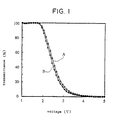
- Fig. 1 of the annexed drawing shows the relationship between the transmittance (%) of a liquid crystal display device and voltage (volt).
- a curve A is drawn for a liquid crystal display device comprising a liquid crystal alignment layer exposed to laser beam and a curve B is drawn for a liquid crystal display device comprising a rubbed liquid crystal alignment layer.
- the organic film for forming a liquid crystal alignment layer is formed from an organic polymer.
- the organic polymer include polyimides, polysulfones, polyesters, polyamides, poly(meth)acrylates, polycarbonates, polyphenylene sulfides, polyphenylene oxides, norbornene resins and the like.
- organic polymers having a secondary transition point (Tg) or melting point (Tm) of at least about 90°C and an SP (solubility parameter) value of at least 8.5 are preferred.
- Tg is more preferably at least 150°C, particularly preferably at least 180°C.
- a polyimide one of the organic polymers, contains recurring units represented by the following formula (I): wherein R 01 is a tetravalent organic group and R 02 is a divalent organic group.
- R 01 is a tetravalent organic group obtained by removing four carboxyl groups from a tetracarboxylic acid and R 02 a divalent organic group obtained by removing two amino groups from a diamine compound.
- the above polyimide can be obtained by reacting a tetracarboxylic dianhydride and a diamine compound in an organic solvent to synthesize a polyamic acid and dehydrating and ring-closing the polyamic acid as required.
- Illustrative examples of the tetracarboxylic dianhydride include 1,2,3,4-butane tetracarboxylic dianhydride, 1,2,3,4-cyclobutane tetracarboxylic dianhydride, 1,2-dimethyl-1,2,3,4-cyclobutane tetracarboxylic dianhydride, 1,3-dimethyl-1,2,3,4-cyclobutane tetracarboxylic dianhydride, 1,3-dichloro-1,2,3,4-cyclobutane tetracarboxylic dianhydride, 1,2,3,4-tetramethyl-1,2,3,4-cyclobutane tetracarboxylic dianhydride, 1,2,3,4-cyclopentane tetracarboxylic dianhydride, 1,2,4,5-cyclohexane tetracarboxylic dianhydride, 3,3',4,4'-dicyclohexyl tetracarbox
- 1,2,3,4-butane tetracarboxylic dianhydride 1,2,3,4-cyclobutane tetracarboxylic dianhydride, 1,3-dimethyl-1,2,3,4-cyclobutane tetracarboxylic dianhydride, 1,2,3,4-cyclopentane tetracarboxylic dianhydride, 2,3,5-tricarboxycyclopentyl acetic dianhydride, 5-(2,5-dioxotetrahydrofural)-3-methyl-3-cyclohexene-1,2-dicarboxylic dianhydride, 1,3,3a,4,5,9b-hexahydro-5-(tetrahydro-2,5-dioxo-3-furanyl)-naphtho[1,2-c]furan-1,3-dione, 1,3,3a,4,5,9b-hexahydro-8-methyl-5-(tetrahydro-2,5-dio
- 1,2,3,4-cyclobutane tetracarboxylic dianhydride 1,3-dimethyl-1,2,3,4-cyclobutane tetracarboxylic dianhydride, 2,3,5-tricarboxycyclopentyl acetic dianhydride, 1,3,3a,4,5,9b-hexahydro-5-(tetrahydro-2,5-dioxo-3-furanyl)-naphtho[1,2-c]furan-1,3-dione, 1,3,3a,4,5,9b-hexahydro-8-methyl-5-(tetrahydro-2,5-dioxo-3-furanyl)-naphtho[1,2-c]furan-1,3-dione, pyromellitic dianhydride and a compound represented by the following formula (5).
- diamine compound used in the synthesis of the above polyamic acid include aromatic diamines such as p-phenylenediamine, m-phenylenediamine, 4,4'-diaminodiphenylmethane, 4,4'-diaminodiphenylethane, 4,4'-diaminodiphenyl sulfide, 4,4'-diaminodiphenyl sulfone, 3,3'-dimethyl-4,4'-diaminobiphenyl, 4,4'-diaminobenzanilide, 4,4'-diaminodiphenyl ether, 1,5-diaminonaphthalene, 3,3'-dimethyl-4,4'-diaminobiphenyl, 5-amino-1-(4'-aminophenyl)-1,3,3-trimethylindane, 6-amino-1-(4'-aminophenyl)-1,3,3-trimethylindane, 6-
- diamine compounds may be used alone or in combination of two or more.
- the acid anhydride group of the tetracarboxylic dianhydride is preferably 0.2 to 2 equivalents, more preferably 0.3 to 1.2 equivalent, per 1 equivalent of the amino group contained in the diamine compound.
- the synthesis reaction of a polyamic acid is generally carried out in an organic solvent at 0 to 150°C, preferably 0 to 100°C for 1 to 48 hours.
- the organic solvent is not limited to a particular kind as long as it can dissolve a reaction product produced by the reaction.
- Illustrative examples of the organic solvent include aprotic polar solvents such as N-methyl-2-pyrrolidone, N,N-dimethylacetoamide, N,N-dimethylformamide, dimethylsulfoxide, ⁇ -butyrolactone, tetramethyl urea and hexamethylphosphor triamide; and phenolic solvents such as m-cresol, xylenol, phenol and phenol halide.
- the amount of the organic solvent used is preferably such that the total amount of the tetracarboxylic dianhydride and the diamine compound is 0.1 to 30 wt% of the total amount of the reaction solution.
- the organic solvent may be used in combination with a poor solvent for a polyamic acid such as an alcohol, ketone, ester, ether, halogenated hydrocarbon or hydrocarbon in such an amount that the produced polyamic acid does not precipitate.
- a poor solvent for a polyamic acid such as an alcohol, ketone, ester, ether, halogenated hydrocarbon or hydrocarbon in such an amount that the produced polyamic acid does not precipitate.
- the poor solvent include methyl alcohol, ethyl alcohol, isopropyl alcohol, cyclohexanol, ethylene glycol, propylene glycol, 1,4-butanediol, triethylene glycol, acetone, methyl ethyl ketone, cyclohexanone, methyl acetate, ethyl acetate, butyl acetate, diethyl oxalate, diethyl malonate, diethyl ether, ethylene glycol methyl ether, ethylene
- a reaction solution containing a polyamic acid dissolved therein can be obtained by the above synthesis reaction.
- This reaction solution is poured into a large amount of a poor solvent to obtain a precipitate, and the precipitate is then dried at a reduced pressure to obtain a polyamic acid.
- the step of dissolving this polyamic acid in an organic solvent again and precipitating it in a poor solvent is carried out once or several times to purify the polyamic acid.
- the polyimide constituting the liquid crystal aligning agent of the present invention can be prepared by dehydrating and ring-closing the above polyamic acid.
- the dehydration and ring closure of the polyamic acid are carried out (i) by heating the polyamic acid, or (ii) by dissolving the polyamic acid in an organic solvent and adding a dehydrating agent and a dehydrating/ring closing catalyst to this solution, and heating as required.
- the reaction temperature is generally 50 to 300°C, preferably 60 to 250°C.
- the reaction temperature is lower than 50°C, a dehydration and ring closure reaction may not proceed sufficiently, while when the reaction temperature is higher than 300°C, the molecular weight of the obtained imidized polymer may lower.
- an acid anhydride such as acetic anhydride, propionic anhydride or trifluoroacetic anhydride can be used as the dehydrating agent.
- the amount of the dehydrating agent used is preferably 0.01 to 20 moles per 1 mole of the recurring unit of the polyamic acid.
- a tertiary amine such as pyridine, collidine, lutidine or triethylamine can be used as the dehydrating/ring closing catalyst.
- the present invention is not limited to these.
- the amount of the dehydrating/ring closing catalyst used is preferably 0.01 to 10 moles per 1 mole of the dehydrating agent.
- Illustrative examples of the organic solvent used in a dehydration and ring closure reaction are the same as those listed for the organic solvent used in the synthesis of the polyamic acid.
- the reaction temperature of the dehydration and ring closure reaction is generally 0 to 180°C, preferably 10 to 150°C.
- the polyimide can be purified by carrying out the same operation as that for purifying the polyamic acid, on the thus obtained reaction solution.
- the polyimide constituting the liquid crystal aligning agent used in the present invention may be of a terminal modified type having a controlled molecular weight.
- this terminal modified polymer for example, the coating characteristics of the liquid crystal aligning agent can be improved without impairing the effect of the present invention.
- This terminal modified polymer can be synthesized by adding an acid monoanhydride, monoamine compound or monoisocyanate compound to a reaction system in the synthesis of the polyamic acid.
- acid monoanhydride examples include maleic anhydride, phthalic anhydride, itaconic anhydride, n-decylsuccinic anhydride, n-dodecylsuccinic anhydride, n-tetradecylsuccinic anhydride, n-hexadecylsuccinic anhydride and the like.
- Illustrative examples of the monoamine compound include aniline, cyclohexylamine, n-butylamine, n-pentylamine, n-hexylamine, n-heptylamine, n-octylamine, n-nonylamine, n-decylamine, n-undecylamine, n-dodecylamine, n-tridecylamine, n-tetradecylamine, n-pentadecylamine, n-hexadecylamine, n-heptadecylamine, n-octadecylamine, n-eicosylamine and the like.
- Illustrative examples of the monoisocyanate compound include phenylisocyanate, naphthylisocyanate and the like.
- the logarithmic viscosity ( ⁇ ln) of the polyamic acid as a precursor of the polyimide constituting the liquid crystal aligning agent used in the present invention is preferably 0.05 to 10 dl/g, more preferably 0.05 to 5 dl/g.
- the value of the logarithmic viscosity ( ⁇ ln) is obtained from the following equation by measuring the viscosity of a solution having a polymer concentration of 0.5 g/100 ml at 30°C using N-methyl-2-pyrrolidone as a solvent.
- ⁇ ln ln(downflow time of solution/downflow time of solvent) (weight concentration of polymer)
- the proportion of the polymer in the liquid crystal aligning agent for forming an organic film as a liquid crystal alignment layer is selected in view of viscosity and volatility. It is preferably 0.1 to 20 wt%, more preferably 1 to 10 wt% of the whole liquid crystal aligning agent. That is, the liquid crystal aligning agent comprising a polymer solution is coated on the surface of a substrate by a printing method, spin coating method or the like, and then dried to form an organic film as an alignment layer material. When the proportion of the polymer is less than 0.1 wt%, the thickness of the organic film is too small, whereby a good liquid crystal alignment layer may not be obtained.
- the proportion of the polymer is more than 20 wt%, the thickness of the organic film is too large to obtain a good liquid crystal alignment layer and the viscosity of the liquid crystal aligning agent increases, whereby its coating properties may be deteriorated.
- the organic solvent for dissolving the polymer is not particularly limited as long as it can dissolve the polymer.
- Illustrative examples of the organic solvent are the same as those listed for the solvent used in the synthesis reaction and the dehydration and ring closure reaction of the polyamic acid.
- the above poor solvents which can be used in combination in the synthesis reaction of the polyamic acid can be also suitably selected and used in combination of the above organic solvent.
- the liquid crystal aligning agent for forming the organic film may contain a functional silane-containing compound or an epoxy group-containing compound to improve the adhesion of the polymer to the surface of the substrate.
- the functional silane-containing compound include 3-aminopropyl trimethoxysilane, 3-aminopropyl triethoxysilane, 2-aminopropyl trimethoxysilane, 2-aminopropyl triethoxysilane, N-(2-aminoethyl)-3-aminopropyl trimethoxysilane, N-(2-aminoethyl)-3-aminopropylmethyl dimethoxysilane, 3-ureidopropyl trimethoxysilane, 3-ureidopropyl triethoxysilane, N-ethoxycarbonyl-3-aminopropyl trimethoxysilane, N-ethoxycarbonyl-3-aminopropyl triethoxysilane, N
- Preferred examples of the epoxy group-containing compound include ethylene glycol diglycidyl ether, polyethylene glycol diglycidyl ether, propylene glycol diglycidyl ether, tripropylene glycol diglycidyl ether, polypropylene glycol diglycidyl ether, neopentyl glycol diglycidyl ether, 1,6-hexanediol diglycidyl ether, glycerine diglycidyl ether, 2,2-dibromoneopentyl glycol diglycidyl ether, 1,3,5,6-tetraglycidyl-2,4-hexanediol, N,N,N',N'-tetraglycidyl-m-xylenediamine, 1,3-bis(N,N-diglycidylaminomethyl)cyclohexane, N,N,N',N'-tetraglycidyl-4,4'-diaminodiphenyl
- the method of producing the liquid crystal alignment layer of the present invention is advantageously carried out as follows, for example.
- a liquid crystal aligning agent containing an organic polymer is coated on a transparent conductive film side of a substrate having the patterned transparent conductive film formed thereon by a roll coating, spinner coating, printing or the like, and the coated surface is heated to form a coating film.
- the substrate may be used a transparent substrate made from glass such as float glass or soda glass or a plastic film such as polyethylene terephthalate, polybutylene terephthalate, polyether sulfone, polycarbonate, polyacrylate, norbornene resin or the like.
- the transparent conductive film formed on one side of the substrate is a NESA film made from SnO 2 or ITO film made from In 2 O 3 -SnO 2 .
- the patterning of the transparent conductive coating is carried out by a photo-etching method, a method using a mask in advance or the like.
- a functional silane-containing compound or a titanate may be coated in advance on the substrate or the transparent conductive film.
- the heating temperature is preferably 80 to 250°C, more preferably 120 to 200°C.
- the thickness of the formed coating film is generally 0.001 to 1 ⁇ m, preferably 0.005 to 0.5 ⁇ m.
- the formed organic film is exposed to polarized pulsed laser beam having an irradiation energy much lower than the lowest critical irradiation energy by which the decomposition by exposure of the surface of the organic film takes place. Molecules in a surface portion of the organic film are aligned by this exposure to form a liquid crystal alignment layer.
- Illustrative examples of the laser include ArF, KrF, XeCl and XeF excimer lasers; solid lasers such as an Nd:YAG laser, Nd:YLF laser, Nd:YNO 4 laser, Ti-sapphire laser and OPO (Opto-Parametric Oscillator) laser, which are excited by a diode or flash lamp; and dye lasers.
- an excimer laser is used in conjunction with a polarizer such as a quartz filter inclined at Brewster angle.
- the wavelength of the laser beam is 193 nm to 532 nm or may be higher than that. It is preferably 193 nm to 355 nm.
- the pulse width of the polarized pulsed laser beam is preferably 5 nsec to 1 msec, for example.
- the incident angle of the polarized laser beam to the organic film is preferably 10° to 40°, the irradiation energy is 1 mJ/cm 2 to 3 mJ/cm 2 per pulse, and the total irradiation amount is preferably 10 mJ/cm 2 to 2 J/cm 2 .
- the pitch interval can be, for example, 90 to 100 nm.
- the alignment direction of molecules in the surface portion depends on the type of the organic polymer, the molecules of the organic polymer at a depth of 50 to 100 nm from the surface are aligned such that they cross the swells at 90°.
- liquid crystal alignment layer having molecules aligned by exposure to polarized pulsed laser beam in its surface portion.
- liquid crystal alignment layer which is composed of a polyimide film having molecules aligned by exposure to polarized pulsed laser beam in its surface portion.
- a liquid crystal cell is constructed by preparing two substrates having the above liquid crystal alignment layer formed thereon, arranging the two substrates to face each other with spacing (cell gap) therebetween in such a manner that the irradiation directions of polarized pulsed laser beam onto the liquid crystal alignment layers become at right angles to each other or antiparallel to each other, sticking together the peripheral portions of the two substrates with a sealing agent, filling liquid crystals into the cell gap defined by the surfaces of the substrates and the sealing agent, and sealing up a filling hole.
- a liquid crystal display device can be obtained by sticking a polarizer to the outer surfaces of the liquid crystal cell, that is, the other sides of the substrates forming the liquid crystal cell in such a manner that the polarizing direction of the polarizer agrees with, or crosses at right angles to, the irradiation direction of polarized pulsed laser beam onto the liquid crystal alignment layer formed on one side of the substrate.
- sealing agent may be used an epoxy resin containing a curing agent and aluminum oxide particles as a spacer.
- the liquid crystal is a nematic liquid crystal or smectic liquid crystal.
- a nematic liquid crystal is preferred, as exemplified by a Schiff's base liquid crystal, azoxy liquid crystal, biphenyl liquid crystal, phenylcyclohexane liquid crystal, ester liquid crystal, terphenyl liquid crystal, biphenylcyclohexane liquid crystal, pyrimidine liquid crystal, dioxane liquid crystal, bicyclooctane liquid crystal, cubane liquid crystal and the like.
- cholesteric liquid crystal such as cholesteryl chloride, cholesteryl nonanoate or cholesteryl carbonate, a chiral agent marketed under the trade name of C-15 or CB-15 (products of Merck & Co., Inc), and the like.
- a ferroelectric liquid crystal such as p-decyloxybenzylidene-p-amino-2-methylbutyl cinnamate can be also used.
- liquid crystal display device comprising the liquid crystal alignment layer of the present invention.
- polarizer used on the outer sides of the liquid crystal cell may be used a polarizer comprising cellulose acetate protective films sandwiching a polarizing film called "H film" which has absorbed iodine while a polyvinyl alcohol is drawn and oriented, or a polarizer composed of the H film itself.
- a soluble polyimide (logarithmic viscosity: 1.3 dl/g) comprising recurring units represented by the following formula and composed of tricarboxycyclopentylacetic dianhydride and 4,4'-diaminodiphenyl methane was used as an organic polymer.
- This polymer was dissolved in ⁇ -butyrolactone to prepare a solution having a solid content of 4 wt%. This solution was filtered with a filter having a pore diameter of 1 ⁇ m to prepare a solution of a liquid crystal aligning agent. The solution was coated on the transparent electrode surface of a glass substrate having the transparent electrode composed of an ITO film to a thickness of 0.1 ⁇ m by a spinner, and dried at 180°C for 1 hour to form a thin film.
- the surface of the thin film was exposed to 3 mJ/cm 2 of polarized Nd-YAG laser beam having a main wavelength of 266 nm from the Quanta-Ray GCR (manufactured by Spectra-Physics) at a pulse frequency of 10 Hz and an incident angle of 15° to form a liquid crystal alignment layer of the present invention.
- an epoxy resin adhesive containing aluminum oxide particles having a diameter of 17 ⁇ m was coated, by a screen printing, on the outer edges, having a liquid crystal alignment layer, of a pair of substrates having the liquid crystal alignment layer of the present invention formed thereon, the pair of substrates were placed one upon the other in such a manner that the liquid crystal alignment layers of the substrates faced each other and the irradiation directions of the pulsed laser beam cross at right angles to each other, and bonded together by pressure, and the adhesive was cured.
- nematic liquid crystals (ZLI-1565 of Merck) were filled into the gap between the pair of substrates from an filling hole for liquid crystals, the filling hole was sealed up with an epoxy adhesive, and a polarizer was stuck to both outer sides of the substrates in such a manner that the polarizing direction of the polarizer agreed with the irradiation direction of pulsed laser beam onto the liquid crystal alignment layer of each of the substrates to produce a liquid crystal display device.
- the aligning properties of the liquid crystals were satisfactory. When a voltage of 5 V was applied, changes in the brightness of the liquid crystal display device in response to ON-OFF of the applied voltage were observed.
- thermosetting polyimide (logarithmic viscosity of a polyamic acid as a precursor: 1.9 dl/g) comprising recurring units represented by the following formula: and composed of pyromellitic acid and 4,4'-diaminodiphenyl methane was used in place of the organic polymer used in Example 1, and the same results as in Example 1 was observed.
- a liquid crystal display device was produced in the same manner as in Example 1 except that polystyrene was used in place of the organic polymer used in Example 1 and the same results as in Example 1 was observed.
- a thin film was formed using the soluble polyimide used in Example 1 in the same manner as in Example 1.
- the obtained thin film was rubbed by a rubbing machine having a roll wound with a rayon cloth at a roll revolution of 500 rpm, a stage moving speed of 1 cm/sec and a pile compression length of 0.4 mm to form a liquid crystal alignment layer.
- an epoxy resin adhesive containing aluminum oxide particles having a diameter of 17 ⁇ m was applied, by a screen printing, onto the outer edges having a liquid crystal alignment layer, of a pair of substrates having the liquid crystal alignment layer of the present invention formed thereon, the pair of substrates were placed one upon the other in such a manner that the liquid crystal alignment layers of the substrates faced each other and the irradiation directions of the pulsed laser beam cross at right angles to each other and bonded together by pressure, and the adhesive was cured.
- liquid crystals were filled and a polarizer was stuck to the substrates in the same manner as in Example 1 to produce a liquid crystal display device.
- the polarizer was stuck in such a manner that the polarizing direction agrees with the rubbing direction of the liquid crystal alignment layer of each of the substrates.
- the transmittance of a normally white TN liquid crystal cell was measured by changing the applied voltage from 1 V to 5 V to evaluate the transmittance-voltage characteristics of the cell in each of the liquid crystal display devices.
- the results are shown in Fig. 1.
- the liquid crystal display device of the present invention exhibited almost the same transmittance-voltage characteristics as those of a liquid crystal display device provided with aligning ability by rubbing.
- liquid crystal alignment layer which effectively aligns molecules in a surface portion of the alignment layer non-destructively without producing dusts or a decomposed product and can provide aligning ability to liquid crystal molecules.
Landscapes
- Physics & Mathematics (AREA)
- Nonlinear Science (AREA)
- Spectroscopy & Molecular Physics (AREA)
- Mathematical Physics (AREA)
- Chemical & Material Sciences (AREA)
- Crystallography & Structural Chemistry (AREA)
- General Physics & Mathematics (AREA)
- Optics & Photonics (AREA)
- Liquid Crystal (AREA)
Claims (13)
- Procédé de production d'une couche d'alignement de cristaux liquides consistant à exposer un film organique à un faisceau laser pulsé polarisé pour aligner les molécules dans une portion de surface du film organique, dans lequel le film organique est exposé au faisceau laser pulsé polarisé avec une énergie de rayonnement de 1 mJ/cm2 à 3 mJ/cm2 par pulsation.
- Procédé selon la revendication 1, dans lequel le film organique est formé d'un polymère organique choisi dans le groupe comprenant les polyimides, les polysulfones, les polyesters, les polyamides, les poly(méth)acrylates, les polycarbonates, les poly(sulfures de phénylène), les poly(oxydes de phénylène) et les résines de norbornène.
- Procédé selon la revendication 2, dans lequel le polymère organique présente un point de transition ou un point de fusion secondaire d'au moins environ 90° et un paramètre de solubilité d'au moins 8,5.
- Procédé selon la revendication 2, dans lequel le polymère organique est un polyimide contenant les unités structurales représentées par la formule (I) suivante :dans laquelle R01 est un groupe organique tétravalent et R02 est un groupe organique divalent.
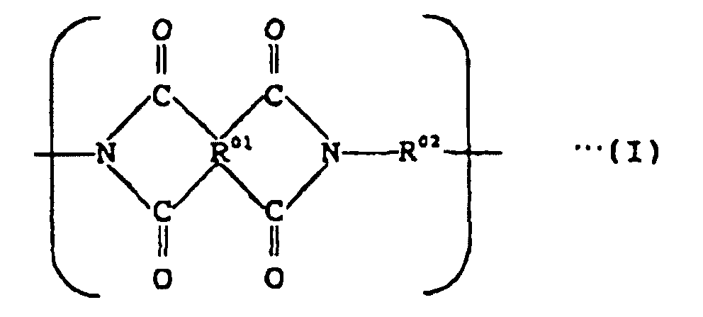
- Procédé selon la revendication 4, dans lequel le groupe organique tétravalent représenté par R01 dans la formule (I) donnée ci-dessus est un groupe résiduel obtenu par l'élimination de quatre groupes carboxyle d'un acide tétracarboxylique et le groupe organique divalent représenté par R02 obtenu par l'élimination de deux groupes amino d'une diamine organique.
- Procédé selon la revendication 1, dans lequel le faisceau laser pulsé polarisé présente une longueur d'onde de 193 nm à 532 nm.
- Procédé selon la revendication 1, dans lequel le faisceau laser pulsé polarisé est envoyé sur le film organique à un angle d'incidence de 10° à 40°.
- Couche d'alignement de cristaux liquides composée d'un film de polyimide ayant des molécules alignées par exposition à un faisceau laser pulsé polarisé, dans une portion de surface, ladite couche est obtenue par le procédé selon la revendication 1.
- Couche d'alignement de cristaux liquides selon la revendication 8, dans lequel un polyimide constituant le film de polyimide contient les unités structurales représentées par la formule (I) suivante :dans laquelle R01 est un groupe organique tétravalent et R02 est un groupe organique divalent.

- Couche d'alignement de cristaux liquides selon la revendication 8, dans lequel le groupe organique tétravalent représenté par R01 dans la formule (I) donnée ci-dessus est un groupe résiduel obtenu par l'élimination de quatre groupes carboxyle d'un acide tétracarboxylique et le groupe organique divalent représenté par R02 est un groupe résiduel obtenu par l'élimination de deux groupes amino d'une diamine organique.
- Couche d'alignement de cristaux liquides selon la revendication 8, dans lequel un polyimide constituant le film de polyimide est obtenu par déshydratation et par cyclisation d'un acide polyamique obtenu à partir d'un dianhydride tétracarboxylique et d'un composé diamine.
- Couche d'alignement de cristaux liquides selon la revendication 8, dans lequel des ondulations parallèles ayant un intervalle de pas pratiquement égal à un intervalle de pas donné par l'équation (VIII) suivante sont formées à la surface du film de polyimide :
- Dispositif d'affichage à cristaux liquides comprenant la couche d'alignement de cristaux liquides selon la revendication 8.
Applications Claiming Priority (3)
| Application Number | Priority Date | Filing Date | Title |
|---|---|---|---|
| JP11270197 | 1997-04-30 | ||
| JP11270197 | 1997-04-30 | ||
| JP112701/97 | 1997-04-30 |
Publications (3)
| Publication Number | Publication Date |
|---|---|
| EP0875781A2 EP0875781A2 (fr) | 1998-11-04 |
| EP0875781A3 EP0875781A3 (fr) | 2000-05-10 |
| EP0875781B1 true EP0875781B1 (fr) | 2005-08-17 |
Family
ID=14593345
Family Applications (1)
| Application Number | Title | Priority Date | Filing Date |
|---|---|---|---|
| EP98107721A Expired - Lifetime EP0875781B1 (fr) | 1997-04-30 | 1998-04-28 | Couche d'orientation pour cristaux liquides, et sa méthode de fabrication |
Country Status (4)
| Country | Link |
|---|---|
| US (1) | US6312769B1 (fr) |
| EP (1) | EP0875781B1 (fr) |
| KR (1) | KR19980081839A (fr) |
| DE (1) | DE69831186T2 (fr) |
Families Citing this family (19)
| Publication number | Priority date | Publication date | Assignee | Title |
|---|---|---|---|---|
| US7074344B2 (en) * | 2001-10-03 | 2006-07-11 | Jsr Corporation | Liquid crystal aligning agent and liquid crystal display element |
| JP3849138B2 (ja) * | 2002-02-18 | 2006-11-22 | Jsr株式会社 | 液晶配向剤、液晶配向膜の形成方法および液晶表示素子 |
| JPWO2003080732A1 (ja) * | 2002-03-26 | 2005-07-21 | 大日本印刷株式会社 | 有機半導体材料、有機半導体構造物、および、有機半導体装置 |
| EP1353217A1 (fr) * | 2002-03-29 | 2003-10-15 | JSR Corporation | Procédé d'alignement optique et dispositif à cristaux liquides |
| JP4600637B2 (ja) * | 2002-04-30 | 2010-12-15 | Jsr株式会社 | 液晶配向剤 |
| KR100917010B1 (ko) * | 2002-11-27 | 2009-09-10 | 삼성전자주식회사 | 배향막 형성 방법 및 장치 |
| WO2004053582A1 (fr) | 2002-12-09 | 2004-06-24 | Hitachi Displays, Ltd. | Ecran a cristaux liquides et son procede de fabrication |
| US7029729B2 (en) * | 2003-02-24 | 2006-04-18 | 3M Innovative Properties Company | Cholesteric liquid crystal additives |
| US7068344B2 (en) * | 2003-02-24 | 2006-06-27 | 3M Innovative Properties Company | Cholesteric liquid crystal optical bodies and methods of manufacture and use |
| US6913708B2 (en) * | 2003-02-24 | 2005-07-05 | 3M Innovative Properties Company | Cholesteric liquid crystal drying process and solvent |
| TWI354002B (en) * | 2003-12-24 | 2011-12-11 | Sumitomo Chemical Co | Epoxy compounds and cured epoxy resin obtained by |
| TWI246608B (en) * | 2004-12-10 | 2006-01-01 | Hon Hai Prec Ind Co Ltd | Method and equipment for manufacturing a polarizer |
| US20060215095A1 (en) * | 2005-03-26 | 2006-09-28 | Qin Liu | Laser-writing alignment marks on alignment layer to align liquid crystals |
| JP2008239679A (ja) * | 2007-03-26 | 2008-10-09 | Sumitomo Chemical Co Ltd | エポキシ樹脂組成物 |
| JP2008266594A (ja) * | 2007-03-26 | 2008-11-06 | Sumitomo Chemical Co Ltd | エポキシ樹脂組成物 |
| KR101056683B1 (ko) * | 2009-01-19 | 2011-08-12 | 주식회사 엘지화학 | 광학 필름, 이의 제조방법, 및 이를 포함하는 액정 표시 장치 |
| KR102069288B1 (ko) * | 2013-08-28 | 2020-01-23 | 삼성디스플레이 주식회사 | 액정 배향제 및 액정 표시 장치 |
| KR101809650B1 (ko) | 2015-10-02 | 2017-12-15 | 주식회사 엘지화학 | 광배향막의 제조 방법 |
| WO2017057854A1 (fr) * | 2015-10-02 | 2017-04-06 | 주식회사 엘지화학 | Procédé de production de couche de photoalignement |
Family Cites Families (16)
| Publication number | Priority date | Publication date | Assignee | Title |
|---|---|---|---|---|
| GB8324642D0 (en) * | 1983-09-14 | 1983-10-19 | Univ Manchester | Liquid crystal storage device |
| JP2537534B2 (ja) * | 1987-03-31 | 1996-09-25 | ユニチカ株式会社 | サ―モトロピック液晶性ポリエステルの製造方法 |
| JP2710779B2 (ja) * | 1987-06-03 | 1998-02-10 | 株式会社クラレ | 高分子液晶化合物への電場印加方法 |
| JP2569406B2 (ja) * | 1989-01-25 | 1997-01-08 | 工業技術院長 | レーザーを用いた液晶配向膜の作製方法 |
| US5073294A (en) * | 1990-03-07 | 1991-12-17 | Hercules Incorporated | Process of preparing compositions having multiple oriented mesogens |
| JP3267989B2 (ja) * | 1991-08-26 | 2002-03-25 | 株式会社東芝 | 液晶配向膜の製造方法 |
| JPH05232472A (ja) | 1992-02-20 | 1993-09-10 | Seiko Instr Inc | 電気光学装置の製造方法 |
| JP2785621B2 (ja) * | 1992-10-16 | 1998-08-13 | 澁谷工業株式会社 | 液晶パネルにおける配向膜の処理方法 |
| JPH06130390A (ja) | 1992-10-19 | 1994-05-13 | Nissin Electric Co Ltd | 配向膜の配向処理方法 |
| EP0977078B1 (fr) * | 1993-01-29 | 2004-07-28 | Sharp Kabushiki Kaisha | Méthode pour la fabrication d'un appareil d'affichage à cristal liquide |
| US5477360A (en) * | 1993-04-23 | 1995-12-19 | Kabushiki Kaisha Toshiba | Liquid crystal display device |
| KR950024007A (ko) * | 1994-01-24 | 1995-08-21 | 이헌조 | 액정표시기판의 배향처리장치 |
| FR2724561B1 (fr) * | 1994-09-19 | 1996-12-13 | Oreal | Utilisation du 2,4-diamino pyrimidine 3-oxyde ou de l'un de ses sels dans le traitement des desordres de la maturation et de la structuration du collagene |
| US5818560A (en) * | 1994-11-29 | 1998-10-06 | Sanyo Electric Co., Ltd. | Liquid crystal display and method of preparing the same |
| US5858273A (en) * | 1995-07-27 | 1999-01-12 | Canon Kabushiki Kaisha | Liquid crystal device |
| US5807498A (en) * | 1996-03-29 | 1998-09-15 | Alliant Techsystems Inc. | Process and materials for aligning liquid crystals and liquid crystal optical elements |
-
1998
- 1998-04-28 EP EP98107721A patent/EP0875781B1/fr not_active Expired - Lifetime
- 1998-04-28 DE DE69831186T patent/DE69831186T2/de not_active Expired - Lifetime
- 1998-04-29 KR KR1019980015341A patent/KR19980081839A/ko not_active Application Discontinuation
- 1998-04-29 US US09/069,169 patent/US6312769B1/en not_active Expired - Lifetime
Also Published As
| Publication number | Publication date |
|---|---|
| DE69831186D1 (de) | 2005-09-22 |
| EP0875781A3 (fr) | 2000-05-10 |
| EP0875781A2 (fr) | 1998-11-04 |
| US6312769B1 (en) | 2001-11-06 |
| KR19980081839A (ko) | 1998-11-25 |
| DE69831186T2 (de) | 2006-06-08 |
Similar Documents
| Publication | Publication Date | Title |
|---|---|---|
| EP0875781B1 (fr) | Couche d'orientation pour cristaux liquides, et sa méthode de fabrication | |
| KR100312150B1 (ko) | 액정배향제및액정표시소자 | |
| EP0840161B1 (fr) | Agent d'alignement de cristaux liquides | |
| KR100798245B1 (ko) | 액정 배향제 및 액정 표시 소자 | |
| KR101150633B1 (ko) | 액정 배향제 및 액정 표시 소자 | |
| KR100794075B1 (ko) | 액정 배향제 및 액정 표시 소자 | |
| JPH10104633A (ja) | 液晶配向剤 | |
| KR100803507B1 (ko) | 수직배향형 액정 배향제 및 이를 이용한 액정 표시 소자 | |
| KR101161447B1 (ko) | 액정 배향제 및 액정 표시 소자 | |
| JP4573039B2 (ja) | 液晶配向剤および液晶表示素子 | |
| JP2000204250A (ja) | 液晶配向剤および液晶表示素子 | |
| JP3603292B2 (ja) | 液晶配向膜の製造方法および液晶表示素子 | |
| JP3889077B2 (ja) | 液晶表示素子 | |
| KR100487053B1 (ko) | 액정배향제 | |
| JP3941080B2 (ja) | 液晶配向膜の製造法 | |
| KR101503933B1 (ko) | 액정 배향제 및 액정 표시 소자 | |
| KR100487047B1 (ko) | 액정배향제 | |
| JP2001311080A (ja) | 液晶配向剤 | |
| JPH09297312A (ja) | 液晶配向剤 | |
| KR100554330B1 (ko) | 액정배향막의제조방법 | |
| JPH10183118A (ja) | 液晶配向剤 | |
| KR20060074859A (ko) | 액정 배향제 및 액정 표시 소자 | |
| JPH10183119A (ja) | 液晶配向剤 | |
| JP2002049039A (ja) | 液晶配向剤、液晶配向膜の形成方法および液晶表示素子 | |
| JP2002049040A (ja) | 液晶配向剤、液晶配向膜の形成方法および液晶表示素子 |
Legal Events
| Date | Code | Title | Description |
|---|---|---|---|
| PUAI | Public reference made under article 153(3) epc to a published international application that has entered the european phase |
Free format text: ORIGINAL CODE: 0009012 |
|
| AK | Designated contracting states |
Kind code of ref document: A2 Designated state(s): DE NL |
|
| AX | Request for extension of the european patent |
Free format text: AL;LT;LV;MK;RO;SI |
|
| PUAL | Search report despatched |
Free format text: ORIGINAL CODE: 0009013 |
|
| AK | Designated contracting states |
Kind code of ref document: A3 Designated state(s): AT BE CH CY DE DK ES FI FR GB GR IE IT LI LU MC NL PT SE |
|
| AX | Request for extension of the european patent |
Free format text: AL;LT;LV;MK;RO;SI |
|
| 17P | Request for examination filed |
Effective date: 20000913 |
|
| AKX | Designation fees paid |
Free format text: DE NL |
|
| 17Q | First examination report despatched |
Effective date: 20011114 |
|
| RAP1 | Party data changed (applicant data changed or rights of an application transferred) |
Owner name: JSR CORPORATION |
|
| GRAP | Despatch of communication of intention to grant a patent |
Free format text: ORIGINAL CODE: EPIDOSNIGR1 |
|
| GRAS | Grant fee paid |
Free format text: ORIGINAL CODE: EPIDOSNIGR3 |
|
| GRAL | Information related to payment of fee for publishing/printing deleted |
Free format text: ORIGINAL CODE: EPIDOSDIGR3 |
|
| GRAS | Grant fee paid |
Free format text: ORIGINAL CODE: EPIDOSNIGR3 |
|
| GRAA | (expected) grant |
Free format text: ORIGINAL CODE: 0009210 |
|
| AK | Designated contracting states |
Kind code of ref document: B1 Designated state(s): DE NL |
|
| REF | Corresponds to: |
Ref document number: 69831186 Country of ref document: DE Date of ref document: 20050922 Kind code of ref document: P |
|
| PLBE | No opposition filed within time limit |
Free format text: ORIGINAL CODE: 0009261 |
|
| STAA | Information on the status of an ep patent application or granted ep patent |
Free format text: STATUS: NO OPPOSITION FILED WITHIN TIME LIMIT |
|
| 26N | No opposition filed |
Effective date: 20060518 |
|
| PGFP | Annual fee paid to national office [announced via postgrant information from national office to epo] |
Ref country code: DE Payment date: 20130419 Year of fee payment: 16 |
|
| REG | Reference to a national code |
Ref country code: DE Ref legal event code: R119 Ref document number: 69831186 Country of ref document: DE |
|
| REG | Reference to a national code |
Ref country code: DE Ref legal event code: R119 Ref document number: 69831186 Country of ref document: DE Effective date: 20141101 |
|
| PG25 | Lapsed in a contracting state [announced via postgrant information from national office to epo] |
Ref country code: DE Free format text: LAPSE BECAUSE OF NON-PAYMENT OF DUE FEES Effective date: 20141101 |
|
| PGFP | Annual fee paid to national office [announced via postgrant information from national office to epo] |
Ref country code: NL Payment date: 20150420 Year of fee payment: 18 |
|
| REG | Reference to a national code |
Ref country code: NL Ref legal event code: MM Effective date: 20160501 |
|
| PG25 | Lapsed in a contracting state [announced via postgrant information from national office to epo] |
Ref country code: NL Free format text: LAPSE BECAUSE OF NON-PAYMENT OF DUE FEES Effective date: 20160501 |