EP0870683A1 - Verfahren und Vorrichtung zum Herstellen (Füllen) von Beutelpackungen für Tabak - Google Patents
Verfahren und Vorrichtung zum Herstellen (Füllen) von Beutelpackungen für Tabak Download PDFInfo
- Publication number
- EP0870683A1 EP0870683A1 EP98104639A EP98104639A EP0870683A1 EP 0870683 A1 EP0870683 A1 EP 0870683A1 EP 98104639 A EP98104639 A EP 98104639A EP 98104639 A EP98104639 A EP 98104639A EP 0870683 A1 EP0870683 A1 EP 0870683A1
- Authority
- EP
- European Patent Office
- Prior art keywords
- bag
- material web
- pressing
- bags
- chamber
- Prior art date
- Legal status (The legal status is an assumption and is not a legal conclusion. Google has not performed a legal analysis and makes no representation as to the accuracy of the status listed.)
- Granted
Links
- 241000208125 Nicotiana Species 0.000 title claims abstract description 10
- 235000002637 Nicotiana tabacum Nutrition 0.000 title claims abstract description 10
- 238000000034 method Methods 0.000 title claims abstract description 10
- 239000000463 material Substances 0.000 claims abstract description 43
- 238000004519 manufacturing process Methods 0.000 claims abstract description 10
- 239000002657 fibrous material Substances 0.000 claims abstract description 5
- 238000003825 pressing Methods 0.000 claims description 21
- 238000003466 welding Methods 0.000 claims description 16
- 238000007639 printing Methods 0.000 claims description 3
- 239000000109 continuous material Substances 0.000 claims 2
- 238000005259 measurement Methods 0.000 claims 1
- 230000006835 compression Effects 0.000 abstract description 5
- 238000007906 compression Methods 0.000 abstract description 5
- 238000007789 sealing Methods 0.000 description 9
- 238000005520 cutting process Methods 0.000 description 7
- 230000008878 coupling Effects 0.000 description 5
- 238000010168 coupling process Methods 0.000 description 5
- 238000005859 coupling reaction Methods 0.000 description 5
- 210000000056 organ Anatomy 0.000 description 3
- 238000012545 processing Methods 0.000 description 3
- 230000001413 cellular effect Effects 0.000 description 2
- 238000004806 packaging method and process Methods 0.000 description 2
- 238000007493 shaping process Methods 0.000 description 2
- 230000000694 effects Effects 0.000 description 1
- 239000011888 foil Substances 0.000 description 1
- 238000003780 insertion Methods 0.000 description 1
- 230000037431 insertion Effects 0.000 description 1
- 238000012544 monitoring process Methods 0.000 description 1
- 238000000465 moulding Methods 0.000 description 1
- 238000002360 preparation method Methods 0.000 description 1
- 239000000700 radioactive tracer Substances 0.000 description 1
- 239000006228 supernatant Substances 0.000 description 1
- 238000012546 transfer Methods 0.000 description 1
- 230000001960 triggered effect Effects 0.000 description 1
- 238000011144 upstream manufacturing Methods 0.000 description 1
Images


Classifications
-
- B—PERFORMING OPERATIONS; TRANSPORTING
- B65—CONVEYING; PACKING; STORING; HANDLING THIN OR FILAMENTARY MATERIAL
- B65B—MACHINES, APPARATUS OR DEVICES FOR, OR METHODS OF, PACKAGING ARTICLES OR MATERIALS; UNPACKING
- B65B29/00—Packaging of materials presenting special problems
-
- B—PERFORMING OPERATIONS; TRANSPORTING
- B65—CONVEYING; PACKING; STORING; HANDLING THIN OR FILAMENTARY MATERIAL
- B65B—MACHINES, APPARATUS OR DEVICES FOR, OR METHODS OF, PACKAGING ARTICLES OR MATERIALS; UNPACKING
- B65B41/00—Supplying or feeding container-forming sheets or wrapping material
- B65B41/18—Registering sheets, blanks, or webs
-
- B—PERFORMING OPERATIONS; TRANSPORTING
- B65—CONVEYING; PACKING; STORING; HANDLING THIN OR FILAMENTARY MATERIAL
- B65B—MACHINES, APPARATUS OR DEVICES FOR, OR METHODS OF, PACKAGING ARTICLES OR MATERIALS; UNPACKING
- B65B63/00—Auxiliary devices, not otherwise provided for, for operating on articles or materials to be packaged
- B65B63/02—Auxiliary devices, not otherwise provided for, for operating on articles or materials to be packaged for compressing or compacting articles or materials prior to wrapping or insertion in containers or receptacles
Definitions
- the invention relates to a method for producing bag packs each with a portion of fibrous material, in particular (Cut) tobacco, one dosed according to weight or quantity Portion squeezed into an open container filled and this is then closed. Furthermore concerns the invention an apparatus for performing the method.
- fibrous material in particular (Cut) tobacco
- Bag packer for fibrous packaging goods especially for Portions of cut tobacco are known (DE 34 09 263). Exactly dosed portions of the tobacco are introduced into a press chamber and filled into an open bag after pressing. This is then in the area of a filling opening closed by a transverse seam.
- the practical requirements go there, such bag packers to develop in terms of performance.
- the invention is therefore the task of bag packers or to improve their functioning in such a way that a higher Performance and a wider range of applications are given.
- the method according to the invention is used to achieve this object characterized for the manufacture or filling of bag packs, that for (tobacco) portions of different sizes Bags of uniform size are used and the portion is compressed in this way is that regardless of the size of the serving fills the bag.
- the solution according to the invention creates a simplification in two ways Regarding: On the one hand, the bag packs can differ Content made on one and the same machine or be filled. On the other hand, despite the Serving size of different contents uniform in size and shape Bags are used. With larger quantities therefore more pressing, one for smaller portions less pressing is provided.
- Another special feature of the invention consists in measures when closing the filled bag.
- the (flat) bag is compressed in the area above the content. After that the seam is closed above the compressed area attached, and because of the compression completely trouble-free.
- the device according to the invention is designed in a special way, namely in particular with regard to press chambers for receiving of servings.
- the peculiarity is that for exact attachment of sealing seams and / or separating cuts the film web precisely controlled and differences in length due to stretching of the film be balanced automatically.
- the area a bag station of the device that is actually funded Length of the film web measured and then a sealing or Cutting unit controlled.
- the otherwise prepared one, namely precisely dosed according to weight Portion 10, is placed in one of several (three) cells 12 a cellular wheel 13 introduced, for example in accordance with the DE 34 09 263.
- the portion is made by rotating the cellular wheel 13 10 inserted into an upwardly open baling chamber 14.
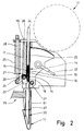
- the portion 10 is compressed and at the same time brought into a certain geometric shape (Fig. 2).
- the portion 10 has due to this pressing or shaping an essentially cuboid shape with two each other opposite large side surfaces 15, 16 and a narrow, elongated top 17.
- the top 17 opposite, ie below, the Portion 10 a tapered or sharp-edged profile 18 having.
- the resulting contour corresponds to the (vertical) Cross-sectional profile of the bag (Fig. 5 to Fig. 7).
- Suitable pressing members are assigned to the pressing chamber 14.
- the Bale chamber 14 is on one side, in the area of the side surface 15, delimited by an (upright) fixed wall 19.
- a movable press wall 20 is arranged. This is designed as a segment and around a lower joint or a lower axis 21 pivotable.
- Fig. 1 In the open position (Fig. 1) there is a funnel-shaped position of the press wall 20 and thus a large filling opening upwards.
- the press wall 20 is movable by a push rod 22 in a pivoting sense 1 in the position shown in FIG. 2 / Fig. 3rd parallel to the fixed wall 19.
- the pressing chamber 14 can be closed by a movable member, namely by a flap 23 which is one with the Fixed wall 19 connected axis 24 is pivotable.
- a flap 23 In the closed position (Fig. 1, Fig. 2) the flap 23 projects in a downward direction directed inclination in the bale chamber 14. This is thus closed at the bottom by a sloping surface.
- the portion 10 is pressurized by the press wall 20 there is a shape corresponding to the interior the press chamber 14, namely with the pointed down tapered profile 18.
- the corresponding shape is given by the flap 23 causes in the closed position.
- the flap 23 is in the direction of the closed position (Fig. 1, Fig. 2) elastically biased by a compression spring 25. This lies with an (upper) end on a support wall 26 on. The other end rests on a ledge or collar 27 from an actuating rod 28 for the flap 23.
- the operating rod 28 is connected to a lever 29 for this purpose, which in turn on the flap 23 or on its axis 24 is appropriate.
- a pivoting movement of the lever 29 - triggered through the actuating rod 28 - leads to a pivoting the flap 23 in one direction or the other.
- the operating rod 28 is, as shown in Fig. 4, upwards extended and is actuated by a curve segment 30.
- a curve segment 30 On whose outer curve 31 is a sensing roller 32 of a double arm Rocker arm 33.
- the other end of the stationary Rocker arm 33 is articulated with the upper end of the operating rod 28 connected.
- the portion 10 is in the press chamber 14 in at least two different Directions pressed together.
- a ram 34 effective from above in the Bale chamber 14 enters.
- the ram 34 has the dimensions (Length, width) of the press chamber 14 in the press position of the press wall 20.
- the ram 34 acts on the top 17 of the portion 10 and presses them together against the support effect of the Flap 23.
- the ram 34 is for this purpose from a upper starting position according to FIG. 1 with the press chamber closed 14 moves downward while compressing the portion 10 the size corresponding to the content of the bag 11, which is shown in FIG. 2 is shown.
- This press position of the press ram 34 is constant, regardless of the amount (weight) of the portion 10, so that always a constant dimension of the packable Portion 10 is created regardless of the amount.
- the ram 34 has another function. After completion of the pressing process and opening of the pressing chamber 14 downwards Swiveling back the flap 23, the pressed portion 10 of the plunger 34 pushed out by continued movement down in the upwardly open bag 11. This is below the press chamber 14 is kept ready by a turret 35, the one for each bag 11 directed downwards Filling mouthpiece 36 has. This is open at the top and bottom and enters this through a bag opening 37.
- the (pressed) Portion 10 is through the ram 34 into the filling mouthpiece 36 of the turret 35 inserted (Fig. 3). After that the ram 34 returns to the (upper) starting position according to Fig. 1 back.
- the turret 35 can be moved one station will.
- the pouch revolver that can be rotated in cycles around a vertical axis 35 is designed for a two-track mode of operation (FIG. 8). Accordingly, the bag turret 35 each has two bags 11 supplied to the bag turret 35 for receiving one each Portion 10 are positioned, namely each on a filling mouthpiece 36. Two receptacles or holders with filling mouthpiece 36 lie side by side on the turret 35.
- the described molding device is also corresponding the portions 10 and filling them into the bag 11 as stationary portioning unit 38 for simultaneous processing set up by two servings.
- Two side by side Bale chambers 14 are on a common support frame 39 attached in the area of a stationary filling station.
- the bale chambers 14 are at a distance from the bag 11 or filling mouthpieces 36 on the turret 35 corresponding distance from each other arranged.
- Each press chamber 14 is a press wall 20 assigned.
- Each press chamber 14 is also provided with a flap 23 Mistake.
- the two flaps 23 of the portion unit 38 are but through a common, centrally located operating rod 28 moves.
- Press rams 34 have a common end at their top Traverse 40 attached. This in turn is on the side with sliders 41, 42 movable on upright guide rods 43, 44.
- a crank drive is used to drive the (two) press rams 34 intended.
- This consists of a coupling rod 45 which with the rotatably mounted curve segment 30 is articulated. By partial rotation of the curve segment 30 is accordingly over the Coupling rod 45 an up and down movement of the cross member 40 and so that the ram 34 causes.
- the stroke of the ram 34 is adjustable in terms of 2.
- the coupling rod 45 is over a manually operable rocker arm 46 releasably on the cross member 40 anchored. After loosening the rocker arm 46, the lifting movement of the ram 34 can be changed. By moving the coupling rod 45 the stroke of the press ram 34 is changed so that that the lower pressing position in the area of the pressing chamber 14 down (smaller format of the compressed portion 10) or upwards (larger format of the pressed portion 10) becomes.
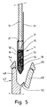
- the filled but open bag 11 is in the area of Locking station held in a pocket 47 open at the top.
- This consists of a fixed, upright side wall 48, one in a funnel-shaped open position (Fig. 4) movable Counter wall 49 and a profile corresponding to the bag 11, in the present case V-shaped bottom wall 50, which is connected to the fixed side wall 48.
- the bag is placed in the open pocket 47 (Fig. 5) from above introduced here.
- the bag opening 37 is a from above Pressure element, namely a pressure plate 51 inserted into the pocket 47, around the (pressed) portion 10 precisely in shape within the Position bag 11.
- the dimensions are made so that above portion 10, a supernatant of two opposite side bag walls 52, 53 created becomes.
- the bag 11 is positively attached to the Bottom wall 50 on.
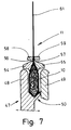
- the pocket 47 is closed by moving the counter wall 49 into a position parallel to the Sidewall 48.
- Now 48 and Counter wall 49 arranged and preferably with these walls connected pressure elements effective.
- the profile of the pressure bars 54, 55 is selected so that a lower cross-sectional area is shaping, namely, leaving a wedge-shaped recess to which Bag walls 52, 53 abuts.
- the bag walls 52, 53 lie in an area above the Portion 10 directly together.
- sealing organs effective namely sealing strips 58, 59. These generate a transverse sealing seam in the area of the bag opening.
- The can be pressure-free and by the action of the pressure bars 54, 55 attached without interference from portions of the portion 10 will.
- Fig. 8 and Fig. 9 Another special feature of the device results from Fig. 8 and Fig. 9. It is about the manufacture of the bag 11. This are made from a continuous web of material 60. Here it is preferably a thermally weldable material, so that side seams of the bag 11 are made by sealing can be. Unless otherwise described below, can this device in the sense of US 4,680,024 be trained.
- the material web 60 is for the production of bags 11 for Includes a pre-folded portion of tobacco, folded with unevenly long legs to form the bag 11 and one unilaterally longer closing flap 61.
- the pre-folded material web 60 is removed from a bobbin by feed rollers 62 withdrawn (not shown) and fed to a web pendulum 63. This controls the tension in the Material web 60.
- the material web 60 is transferred to a treatment unit via deflection rollers 64, 65 fed, namely a welding station 66. Im Areas of the same become during a standstill phase of the material web 60 welded or sealed seams attached to it, namely in particular transverse side seams of the bag 11 to be produced.
- the welding station 66 is so designed that seals for four during a work cycle successive bags 11 within the material web 60 getting produced. The welding station 66 is then opened and advanced the material web by a corresponding section.
- the material web provided with the side seams for the bag 11 is via a deflection roller connected to the welding station 66 67 as well as further deflection rollers 68 and 69 one Cutting station 70 fed.
- a deflection roller connected to the welding station 66 67 as well as further deflection rollers 68 and 69 one Cutting station 70 fed.
- the separating cuts are made in the area of the transverse or side seams of the material web 60 carried out.
- the separated bags 11 are replaced by a Bag conveyor 71, namely a (suction) belt, the one held ready Holders for the bags on the turret 35 fed.
- a special feature of the facility is that movement compensation in the area before and after welding station 66 is performed.
- movement compensation in the area before and after welding station 66 is performed.
- the material web 60 in front of this processing station for example, corresponding to four bags 11 Section is funded in cycles, is the (in sections) preference of the material web 60 in the area of Cutting station 70 and before that only the length of a single bag 11.
- a compensation body This exists from a reciprocable carriage 72. About this Areas of the material web 60 run before and after the carriage Welding station 66, in each case via the deflection roller 64 on the one hand and the deflection roller 69 on the other. The web of material 60 runs on both sides of these deflection rollers 64 and 69 along a section in parallel runs.
- the carriage 72 is back and forth with the deflection rollers 64 and 69 movable, namely from the right shown in FIG. 8 Position in an opposite end position adjacent to Deflection roller 68.
- a clockwise begins Drawing off a formed web supply 73 by feeding (Short) path sections to the cutting station 70.
- the advantage of the track is through (contactless) touch elements monitored, namely by a photocell 74. This is in the present Trap on the entry side in front of welding station 66 positioned. The photocell 74 reacts to the correct position arranged print marks 76 on the material web 60. Another Photocell 75 is arranged upstream of cutting station 70 by the feed lengths to control for this cutting station 70.
- a special feature of the device is that these changes in length the web of material 60 by stretching or shrinking recognizes and compensates. Especially with foils Plastic can cause such changes in length by stretching the Material web 60 occur.
- the device is actually funded Length of material web 60 (additionally) determined.
- At the present embodiment is at least one of the Deflection rollers, namely the one positioned at the exit of the welding station 66 Deflection roller 67, with a monitoring element for Determine the actually conveyed length of the material web 60 provided.
- It is preferably a known, usual resolver 77, i.e. around an angle step encoder. This measures exactly the conveyed length of the web based on the revolutions the guide roller 67. Any differences due to stretching of the material web 60 lead to an offset of the print mark 76 (Fig. 9). This difference becomes when the next succeeding Section of the material web 60 balanced, namely on best by reducing the feed length accordingly. This also leads to an offset relative position of the slide 72 in one or the other end position (Fig. 9).
- the movement compensation of the differently funded areas the material web 60 and the device for compensating for changes in length in the material web 60 can also be in another Connection with packaging machines.
Landscapes
- Engineering & Computer Science (AREA)
- Mechanical Engineering (AREA)
- Auxiliary Devices For And Details Of Packaging Control (AREA)
Abstract
Description
- Fig. 1
- eine Einzelheit der Vorrichtung, nämlich eine Füll-station, im Vertikalschnitt,
- Fig. 2
- die Aggregate der Füllstation gemäß Fig. 1 in Preßstellung,
- Fig. 3
- eine Stellung der Aggregate gemäß Fig. 1 und 2 beim Befüllen eines Beutels,
- Fig. 4
- die Füllstation gemäß Fig. 1 bis Fig. 3 in Draufsicht,
- Fig. 5
- eine Einzelheit der Vorrichtung im Vertikalschnitt, nämlich die Vorbereitung eines Beutels zum Verschließen,
- Fig. 6
- die Einzelheit gemäß Fig. 5 in einer weiteren Phase des Verschließens,
- Fig. 7
- die Einzelheit gemäß Fig. 5 und Fig. 6 beim Schließen des Beutels,
- Fig. 8
- eine Gesamtansicht (Draufsicht) einer Vorrichtung zum Herstellen und Füllen von Beuteln in stark vereinfachter Darstellung,
- Fig. 9
- eine Einzelheit der Vorrichtung gemäß Fig. 8, nämlich einen Ausschnitt, in stark vergrößertem Maßstab.
- 10
- Portion
- 11
- Beutel
- 12
- Zelle
- 13
- Zellenrad
- 14
- Preßkammer
- 15
- Seitenfläche
- 16
- Seitenfläche
- 17
- Oberseite
- 18
- Profil
- 19
- Festwand
- 20
- Preßwand
- 21
- Achse
- 22
- Schubstange
- 23
- Klappe
- 24
- Achse
- 25
- Druckfeder
- 26
- Stützwand
- 27
- Bund
- 28
- Betätigungsstange
- 29
- Hebel
- 30
- Kurvensegment
- 31
- Außenkurve
- 32
- Tastrolle
- 33
- Kipphebel
- 34
- Preßstößel
- 35
- Beutelrevolver
- 36
- Füllmundstück
- 37
- Beutelöffnung
- 38
- Portionsaggregat
- 39
- Traggestell
- 40
- Traverse
- 41
- Gleitstück
- 42
- Gleitstück
- 43
- Führungsstange
- 44
- Führungsstange
- 45
- Koppelstange
- 46
- Kipphebel
- 47
- Tasche
- 48
- Seitenwand
- 49
- Gegenwand
- 50
- Bodenwand
- 51
- Druckplatte
- 52
- Beutelwand
- 53
- Beutelwand
- 54
- Druckleiste
- 55
- Druckleiste
- 56
- Druckkante
- 57
- Druckkante
- 58
- Siegelleiste
- 59
- Siegelleiste
- 60
- Materialbahn
- 61
- Schließlappen
- 62
- Vorzugwalze
- 63
- Bahnpendel
- 64
- Umlenkrolle
- 65
- Umlenkrolle
- 66
- Schweißstation
- 67
- Umlenkwalze
- 68
- Umlenkwalze
- 69
- Umlenkwalze
- 70
- Schneidstation
- 71
- Beutelförderer
- 72
- Schlitten
- 73
- Bahnvorrat
- 74
- Fotozelle
- 75
- Fotozelle
- 76
- Druckmarke
- 77
- Resolver
Claims (14)
- Verfahren zum Herstellen von Beutelpackungen mit jeweils einer Portion (10) faserigen Materials, insbesondere (Schnitt-) Tabak, wobei eine nach Gewicht oder Menge dosierte Portion (10) zusammengepreßt, in einen oben offenen Beutel (11) eingefüllt und dieser danach verschlossen wird, dadurch gekennzeichnet, daS zur Herstellung von Beutelpackungen mit Portionen unterschiedlicher Größe (Gewicht) Beutel (11) einheitlicher Größe verwendet und die jeweils einzufüllende Portion (10) derart zusammengepreßt wird, daß unabhängig vom Gewicht der Portion (10) der Beutel (11) durch die Portion (10) gefüllt ist.
- Verfahren nach Anspruch 1, dadurch gekennzeichnet, daß die Portion (10) in einer Preßkammer (14) in zwei quer zueinander weisenden Richtungen verpreßt wird, insbesondere derart, daß bei einer flachen, etwa quaderförmig geformten Portion (10) diese zuerst flach zusammengedrückt und sodann durch Druck auf eine obere, schmale Oberseite (17) in Querrichtung verpreßt wird.
- Verfahren nach Anspruch 1 oder 2, dadurch gekennzeichnet, daß die Portion (10) beim Verpressen in der Preßkammer (14) in eine nach unten konvergierende Form, insbesondere mit einem unteren konvergierenden Profil (18) verformt wird.
- Verfahren nach Anspruch 1 oder einem der weiteren Ansprüche, dadurch gekennzeichnet, daß der Beutel (11) nach Einfüllen der Portion (10) in einem Bereich oberhalb derselben und unterhalb einer Beutelöffnung (37) zusammengedrückt und daß sodann oberhalb des zusammengedrückten Bereichs ein Beutelverschluß angebracht wird, insbesondere eine Beutelwände (52, 53) miteinander verbindende Verschlußnaht.
- Verfahren nach Anspruch 1 oder einem der weiteren Ansprüche, dadurch gekennzeichnet, daß Zuschnitte bzw. die Beutel (11) von einer fortlaufenden Materialbahn (60) nacheinander abgetrennt werden und daß die Materialbahn in einer Behandlungsstation, insbesondere in einer Schweißstation (66) vorbereitet, insbesondere verschweißt wird, wobei unterschiedliche Fördercharakteristika im Bereich vor und nach der Behandlungsstation, insbesondere unterschiedliche taktweise Förderabschnitte, durch ein bewegbares Umlenkorgan, insbesondere einen Schlitten (72) mit Umlenkwalzen (64 und 69), ausgeglichen werden.
- Verfahren nach Anspruch 1 oder einem der weiteren Ansprüche, dadurch gekennzeichnet, daß die Materialbahn (60) mit Hilfe von (Druck-)Marken abgetastet wird und daß etwaige Änderungen der Länge der Materialbahn (60), insbesondere durch Dehnung oder Schrumpfung, durch zusätzliche Messung der tatsächlich geförderten Länge der Materialbahn (60) festgestellt und danach die Relativstellung bzw. die aktuell geförderte Länge der Materialbahn (60) eingestellt wird.
- Vorrichtung zum Füllen von Beutelpackungen mit Portionen (10) faserigen Materials, insbesondere Portionen (10) von Schnittabak, wobei hinsichtlich Menge und/oder Gewicht dosierte Portionen (10) über eine Preßkammer (14) in einen oben offenen Beutel (11) einfüllbar sind, dadurch gekennzeichnet, daß die Preßkammer zum Zusammenpressen der Portion (10) mindestens zwei bewegbare Kammerbegrenzungen aufweist, nämlich insbesondere eine bewegbare Preßwand (20) und einen hierzu in Querrichtung bewegbaren Preßstößel (34), der nach Bewegen der Preßwand in die Preßstellung bis auf eine festgelegte (untere) Preßstellung absenkbar ist.
- Vorrichtung nach Anspruch 7, dadurch gekennzeichnet, daß eine untere (schlitzförmige) Austrittsöffnung der Preßkammer (14) durch ein bewegbares Verschlußorgan absperrbar ist, insbesondere durch eine schwenkbare Klappe (23), die zum Ausschub der Portion (10) aus dem Bereich der Preßkammer (14) herausbewegbar ist.
- Vorrichtung nach Anspruch 8, dadurch gekennzeichnet, daß die Portion (10) in der Preßkammer (14) hinsichtlich der Querschnittsgestalt formierbar ist, insbesondere mit einem unteren durch die Klappe (23) geformten Profil (18).
- Vorrichtung nach Anspruch 7 oder einem der weiteren Ansprüche, dadurch gekennzeichnet, daß einander gegenüberliegende Beutelwände (52, 53) nach dem Einführen einer Portion (10) unterhalb einer Beutelöffnung (37), jedoch oberhalb der Portion (10) zusammendrückbar sind, insbesondere durch Druckleisten (54, 55) und daß oberhalb derselben eine Verschlußnaht herstellbar ist, insbesondere durch Siegel leisten (58, 59).
- Vorrichtung nach Anspruch 10, dadurch gekennzeichnet, daß der Beutel (11) zur Herstellung der Verschlußnaht in gesonderten Taschen (47) einsetzbar ist, die dem Profil des Beutels (11) im unteren Bereich entsprechen und daß eine Druckplatte (51) über die offene Beutelöffnung (37) die Formgebung der Portion (10) innerhalb des Beutels (11) aufrechterhält.
- Vorrichtung nach Anspruch 7 oder einem der weiteren Ansprüche, dadurch gekennzeichnet, daß eine fortlaufende Materialbahn (60) zum Fertigen der Beutel (11) oder dergleichen mit unterschiedlichen Bewegungscharakteristika vor und nach einer Behandlungsstation, insbesondere einer Schweißstation (66) transportierbar ist, insbesondere mit unterschiedlichen taktweisen Vorzugslängen und daß die Bewegungsdifferenzen durch ein bewegbares Ausgleichsorgan, insbesondere einen hin- und herbewegbaren Schlitten (72), ausgeglichen werden.
- Vorrichtung nach Anspruch 12, dadurch gekennzeichnet, daß die Materialbahn (60) mit einem Bereich vor der Behandlungsstation bzw. Schweißstation (66) einerseits und mit einem Bereich im Anschluß an die Behandlungsstation jeweils über Umlenkrollen (64, 69) des Schlittens (72) läuft.
- Vorrichtung nach Anspruch 7 oder einem der weiteren Ansprüche, dadurch gekennzeichnet, daß eine Materialbahn (60) zum Herstellen der Beutel (11) oder dergleichen mit Hilfe von Druckmarken (76) und Abtastorganen, insbesondere Fotozellen (74, 75), hinsichtlich der Förderbewegung steuerbar ist und daß zusätzlich die effektiv geförderte Länge der Materialbahn (60) meßbar ist, insbesondere durch einen im Bereich einer Umlenkwalze (67) für die Materialbahn (60) angeordneten Resolver (77).
Applications Claiming Priority (2)
| Application Number | Priority Date | Filing Date | Title |
|---|---|---|---|
| DE19714245 | 1997-04-07 | ||
| DE19714245A DE19714245A1 (de) | 1997-04-07 | 1997-04-07 | Verfahren und Vorrichtung zum Herstellen (Füllen) von Beutelpackungen für Tabak |
Publications (2)
| Publication Number | Publication Date |
|---|---|
| EP0870683A1 true EP0870683A1 (de) | 1998-10-14 |
| EP0870683B1 EP0870683B1 (de) | 2004-05-26 |
Family
ID=7825651
Family Applications (1)
| Application Number | Title | Priority Date | Filing Date |
|---|---|---|---|
| EP98104639A Expired - Lifetime EP0870683B1 (de) | 1997-04-07 | 1998-03-14 | Verfahren und Vorrichtung zum Herstellen (Füllen) von Beutelpackungen für Tabak |
Country Status (3)
| Country | Link |
|---|---|
| US (1) | US6044624A (de) |
| EP (1) | EP0870683B1 (de) |
| DE (2) | DE19714245A1 (de) |
Cited By (1)
| Publication number | Priority date | Publication date | Assignee | Title |
|---|---|---|---|---|
| WO2009059729A3 (de) * | 2007-11-09 | 2009-07-02 | Focke & Co | Verfahren und vorrichtung zum füllen und verschliessen von tabakbeuteln |
Families Citing this family (13)
| Publication number | Priority date | Publication date | Assignee | Title |
|---|---|---|---|---|
| DE102008007737A1 (de) * | 2008-02-05 | 2009-08-06 | Focke & Co.(Gmbh & Co. Kg) | Vorrichtung zum Handhaben von (Tabak-) Beuteln |
| DE102008015082A1 (de) | 2008-03-19 | 2009-09-24 | Focke & Co.(Gmbh & Co. Kg) | Verfahren und Vorrichtung zum Herstellen von Beutelpackungen |
| US8991142B2 (en) | 2010-02-03 | 2015-03-31 | Altria Client Services Inc. | Apparatus for dispensing moist smokeless tobacco |
| IT1400655B1 (it) * | 2010-06-30 | 2013-06-28 | Azionaria Costruzioni Acma Spa | Macchina e metodo di confezionamento di materiale in fibra. |
| US20120317935A1 (en) * | 2011-06-15 | 2012-12-20 | Peter Richard Antoniak | Device to aid in the recycling of plastic bags by inserting them into used consumer liquid products containers for compact storage and transport |
| ITBO20110726A1 (it) * | 2011-12-16 | 2013-06-17 | Gd Spa | Metodo e macchina per la produzione di buste contenenti materiale in fibra. |
| ITBO20110727A1 (it) * | 2011-12-16 | 2013-06-17 | Gd Spa | Metodo e macchina per la produzione di buste contenenti materiale in fibra. |
| ITBO20110725A1 (it) * | 2011-12-16 | 2013-06-17 | Gd Spa | Metodo e macchina per la produzione di buste contenenti materiale in fibra. |
| ITBO20110724A1 (it) | 2011-12-16 | 2012-03-16 | Gd Spa | Metodo e macchina per la produzione di buste contenenti materiale in fibra. |
| ITBO20110728A1 (it) * | 2011-12-16 | 2013-06-17 | Gd Spa | Metodo e macchina per la produzione di buste contenenti materiale in fibra. |
| DE102012110800A1 (de) | 2012-11-09 | 2014-05-15 | Khs Gmbh | Maschine zum Füllen von Beuteln |
| ES2478421B1 (es) * | 2014-02-21 | 2015-06-02 | Bossar Packaging, S.A. | Máquina envasadora con dispositivo compensador de errores de impresión del film |
| DE102023135703A1 (de) * | 2023-12-19 | 2025-06-26 | Focke & Co. (Gmbh & Co. Kg) | Verfahren und Vorrichtung zum Befüllen eines Beutels mit einer Portion faserigen Materials |
Citations (4)
| Publication number | Priority date | Publication date | Assignee | Title |
|---|---|---|---|---|
| US2915866A (en) * | 1958-05-12 | 1959-12-08 | Lynch Corp | Product settling means for draw type wrapping machine |
| FR2237430A7 (en) * | 1973-10-12 | 1975-02-07 | Patentimmo Anstalt | Double piston baling machine - vertical piston compresses charge horizontal piston ejects charge |
| DE3409263A1 (de) * | 1984-03-14 | 1985-09-19 | Focke & Co, 2810 Verden | Verfahren und vorrichtung zum verpacken von tabak-portionen |
| US4680024A (en) * | 1984-12-20 | 1987-07-14 | Focke & Co., (Gmbh & Co.) | Apparatus for producing bags from a tubular sheet of thermally weldable film material |
Family Cites Families (20)
| Publication number | Priority date | Publication date | Assignee | Title |
|---|---|---|---|---|
| DE427579C (de) * | 1924-11-27 | 1926-04-12 | Ewald Koerner | Vorrichtung zum Verpacken von Tabak, Tee o. dgl. Stoffen |
| DE1034092B (de) * | 1956-02-11 | 1958-07-10 | Quester Fa Wilh | Verfahren und Vorrichtung zum selbsttaetigen Fuellen von Beutelpackungen mit faserigem Gut, insbesondere Tabak |
| US3091903A (en) * | 1960-02-16 | 1963-06-04 | Storrac Inc | Receptacle filling apparatus |
| SE324533B (de) * | 1967-11-28 | 1970-06-01 | Antonson Avery Ab | |
| GB1427345A (en) * | 1972-08-09 | 1976-03-10 | Douwe Egberts Tabaksmij | Dosing and weighing of cut tobacco |
| JPS5211268B2 (de) * | 1973-02-06 | 1977-03-30 | ||
| DE2655036A1 (de) * | 1976-12-04 | 1978-06-08 | Schmermund Maschf Alfred | Verfahren zum portionieren von kau- oder schnupftabak und vorrichtung zum durchfuehren des verfahrens |
| US4583352A (en) * | 1983-07-14 | 1986-04-22 | Franrica Mfg. Inc. | Apparatus and methods for automaticaly handling aseptic fitmentless pouch |
| DE3335754A1 (de) * | 1983-10-01 | 1985-04-18 | J. Rettenmaier & Söhne GmbH + Co, 7091 Rosenberg | Verfahren und vorrichtung zum abpacken von losem fuellgut |
| SE450566B (sv) * | 1983-12-14 | 1987-07-06 | Svenska Tobaks Ab | Anordning for att portionsforpacka snus |
| EP0190189A1 (de) * | 1984-07-12 | 1986-08-13 | Amf Incorporated | Tütenfaltvorrichtung |
| EP0229216B1 (de) * | 1985-12-28 | 1991-10-09 | Tokyo Automatic Machinery Works Limited | Verpackungsmaschine mit einer Beutelherstellungs- und Füllvorrichtung |
| US4757668A (en) * | 1986-01-27 | 1988-07-19 | Ilapak Research & Development S.A. | Method and apparatus for form-fill-seal packaging of articles |
| CH671198A5 (de) * | 1986-07-31 | 1989-08-15 | Ilapak Res & Dev Sa | |
| DE3721675A1 (de) * | 1987-07-01 | 1989-01-12 | Alfons Meyer | Wickel- oder sogenannter pouchbeutel aus thermoplastischem folienmaterial zum verpacken beispielsweise von rauchtabak |
| DE4111786A1 (de) * | 1990-04-26 | 1992-01-02 | Focke & Co | Verfahren und vorrichtung zum herstellen von beutelartigen packungen fuer insbesondere kautabakersatz |
| DE9203841U1 (de) * | 1992-03-21 | 1992-05-21 | Hassia-Redatron GmbH, 6338 Hüttenberg | Vorrichtung zum volumenreduzierten Verpacken von Schüttgut in Schlauchbeutel |
| US5425215A (en) * | 1993-04-16 | 1995-06-20 | Brown & Williamson Tobacco Corporation | Apparatus for packaging loose leaf material |
| US5459982A (en) * | 1994-04-14 | 1995-10-24 | Schuller International, Inc. | Apparatus for densifying and packaging bulky materials |
| US5727366A (en) * | 1997-04-10 | 1998-03-17 | Milliken Research Corporation | Registration control |
-
1997
- 1997-04-07 DE DE19714245A patent/DE19714245A1/de not_active Withdrawn
-
1998
- 1998-03-14 DE DE59811444T patent/DE59811444D1/de not_active Expired - Lifetime
- 1998-03-14 EP EP98104639A patent/EP0870683B1/de not_active Expired - Lifetime
- 1998-04-02 US US09/054,376 patent/US6044624A/en not_active Expired - Fee Related
Patent Citations (4)
| Publication number | Priority date | Publication date | Assignee | Title |
|---|---|---|---|---|
| US2915866A (en) * | 1958-05-12 | 1959-12-08 | Lynch Corp | Product settling means for draw type wrapping machine |
| FR2237430A7 (en) * | 1973-10-12 | 1975-02-07 | Patentimmo Anstalt | Double piston baling machine - vertical piston compresses charge horizontal piston ejects charge |
| DE3409263A1 (de) * | 1984-03-14 | 1985-09-19 | Focke & Co, 2810 Verden | Verfahren und vorrichtung zum verpacken von tabak-portionen |
| US4680024A (en) * | 1984-12-20 | 1987-07-14 | Focke & Co., (Gmbh & Co.) | Apparatus for producing bags from a tubular sheet of thermally weldable film material |
Cited By (2)
| Publication number | Priority date | Publication date | Assignee | Title |
|---|---|---|---|---|
| WO2009059729A3 (de) * | 2007-11-09 | 2009-07-02 | Focke & Co | Verfahren und vorrichtung zum füllen und verschliessen von tabakbeuteln |
| US8528307B2 (en) | 2007-11-09 | 2013-09-10 | Focke & Co. (Gmbh & Co. Kg) | Method of, and apparatus for, filling and closing tobacco bags |
Also Published As
| Publication number | Publication date |
|---|---|
| EP0870683B1 (de) | 2004-05-26 |
| DE19714245A1 (de) | 1998-10-08 |
| US6044624A (en) | 2000-04-04 |
| DE59811444D1 (de) | 2004-07-01 |
Similar Documents
| Publication | Publication Date | Title |
|---|---|---|
| EP0424991B1 (de) | Verfahren und Vorrichtung zum Verpacken von Gegenständen | |
| EP0870683B1 (de) | Verfahren und Vorrichtung zum Herstellen (Füllen) von Beutelpackungen für Tabak | |
| DE3150447C2 (de) | ||
| EP3003870B1 (de) | Verfahren und vorrichtung zum herstellen von packungen, insbesondere zigarettenpackungen | |
| DE2615270A1 (de) | Verfahren und vorrichtung zum verpacken von schuettguetern | |
| CH637342A5 (de) | Verfahren und vorrichtung zum selbsttaetigen befuellen von beuteln in einer fuellstation. | |
| CH459045A (de) | Verfahren zum Herstellen prallvoller Beutelpackungen | |
| DE4035352A1 (de) | Vorrichtung zum herstellen von schachteln und zum verpacken von produkten in diese | |
| DE102008015082A1 (de) | Verfahren und Vorrichtung zum Herstellen von Beutelpackungen | |
| DE2404826A1 (de) | Vorrichtung zum formen von packungen | |
| DE2261678A1 (de) | Komprimieranlage | |
| DE1278323B (de) | Vorrichtung zum Herstellen von Weichbeuteln und zu deren UEberfuehren an eine Beutelfuell- und Schliessmaschine | |
| CH658632A5 (de) | Verfahren zum abpacken von schlauchbeuteln in schachteln, sowie vorrichtung zur durchfuehrung des verfahrens. | |
| EP0513439A1 (de) | Vorrichtung zum Füllen und Verschliessen von Fliessmittelpackungen | |
| DE4035350A1 (de) | Bearbeitungslinie fuer vorrichtungen zur herstellung von verpackungen | |
| DE2636320C2 (de) | Vorrichtung zum automatischen Palettieren von Gegenständen, insbesondere Flaschen | |
| DE3335754A1 (de) | Verfahren und vorrichtung zum abpacken von losem fuellgut | |
| DE2856523A1 (de) | Verfahren und vorrichtung zum einsacken und wiegen von in saecke abgefuellten produkten | |
| DE68904758T2 (de) | Horizontal arbeitender beutelverpackungsautomat. | |
| DE2444513A1 (de) | Vorrichtung zum zusammendruecken von in versandbehaeltern verpackten gefuellten schlauch- und flachbeutel | |
| DE2410101A1 (de) | Vorrichtung zum ausformen von packungen | |
| DE102020208644A1 (de) | Vorrichtung und Verfahren zur Anordnung von Produkten im Bereich einer Quersiegeleinrichtung einer Schlauchbeutelverpackungsmaschine | |
| DE1801206A1 (de) | Vorrichtung zur Herstellung und Verpackung von Ballen aus pulvrigem,koernigem,faserigem oder spanfoermigem Gut,insbesondere aus Holzmehl | |
| DE1511661A1 (de) | Maschine zum Formen,Fuellen und Konfektionieren von Beuteln,die lose eingefuellte,koernige,pulverige oder aehnliche Produkte zum Aufgiessen enthalten | |
| DE1486954C3 (de) | Verfahren und Vorrichtung zur Herstellung von mit einem Träger aus steifem Material versehenen Tiefziehbehältern |
Legal Events
| Date | Code | Title | Description |
|---|---|---|---|
| PUAI | Public reference made under article 153(3) epc to a published international application that has entered the european phase |
Free format text: ORIGINAL CODE: 0009012 |
|
| AK | Designated contracting states |
Kind code of ref document: A1 Designated state(s): BE DE FR GB IT NL |
|
| AX | Request for extension of the european patent |
Free format text: AL;LT;LV;MK;RO;SI |
|
| 17P | Request for examination filed |
Effective date: 19990331 |
|
| AKX | Designation fees paid |
Free format text: BE DE FR GB IT NL |
|
| GRAH | Despatch of communication of intention to grant a patent |
Free format text: ORIGINAL CODE: EPIDOS IGRA |
|
| GRAS | Grant fee paid |
Free format text: ORIGINAL CODE: EPIDOSNIGR3 |
|
| GRAA | (expected) grant |
Free format text: ORIGINAL CODE: 0009210 |
|
| AK | Designated contracting states |
Kind code of ref document: B1 Designated state(s): BE DE FR GB IT NL |
|
| REG | Reference to a national code |
Ref country code: GB Ref legal event code: FG4D Free format text: NOT ENGLISH |
|
| REF | Corresponds to: |
Ref document number: 59811444 Country of ref document: DE Date of ref document: 20040701 Kind code of ref document: P |
|
| GBT | Gb: translation of ep patent filed (gb section 77(6)(a)/1977) |
Effective date: 20040909 |
|
| RAP2 | Party data changed (patent owner data changed or rights of a patent transferred) |
Owner name: FOCKE & CO. (GMBH & CO. KG) |
|
| NLT2 | Nl: modifications (of names), taken from the european patent patent bulletin |
Owner name: FOCKE & CO. (GMBH & CO. KG) |
|
| ET | Fr: translation filed | ||
| PLBE | No opposition filed within time limit |
Free format text: ORIGINAL CODE: 0009261 |
|
| STAA | Information on the status of an ep patent application or granted ep patent |
Free format text: STATUS: NO OPPOSITION FILED WITHIN TIME LIMIT |
|
| 26N | No opposition filed |
Effective date: 20050301 |
|
| REG | Reference to a national code |
Ref country code: FR Ref legal event code: PLFP Year of fee payment: 18 |
|
| PGFP | Annual fee paid to national office [announced via postgrant information from national office to epo] |
Ref country code: NL Payment date: 20150309 Year of fee payment: 18 Ref country code: IT Payment date: 20150309 Year of fee payment: 18 |
|
| PGFP | Annual fee paid to national office [announced via postgrant information from national office to epo] |
Ref country code: GB Payment date: 20150311 Year of fee payment: 18 Ref country code: FR Payment date: 20150309 Year of fee payment: 18 |
|
| PGFP | Annual fee paid to national office [announced via postgrant information from national office to epo] |
Ref country code: BE Payment date: 20150311 Year of fee payment: 18 |
|
| PGFP | Annual fee paid to national office [announced via postgrant information from national office to epo] |
Ref country code: DE Payment date: 20150326 Year of fee payment: 18 |
|
| PG25 | Lapsed in a contracting state [announced via postgrant information from national office to epo] |
Ref country code: BE Free format text: LAPSE BECAUSE OF NON-PAYMENT OF DUE FEES Effective date: 20160331 |
|
| REG | Reference to a national code |
Ref country code: DE Ref legal event code: R119 Ref document number: 59811444 Country of ref document: DE |
|
| REG | Reference to a national code |
Ref country code: NL Ref legal event code: MM Effective date: 20160401 |
|
| GBPC | Gb: european patent ceased through non-payment of renewal fee |
Effective date: 20160314 |
|
| REG | Reference to a national code |
Ref country code: FR Ref legal event code: ST Effective date: 20161130 |
|
| PG25 | Lapsed in a contracting state [announced via postgrant information from national office to epo] |
Ref country code: NL Free format text: LAPSE BECAUSE OF NON-PAYMENT OF DUE FEES Effective date: 20160401 Ref country code: GB Free format text: LAPSE BECAUSE OF NON-PAYMENT OF DUE FEES Effective date: 20160314 Ref country code: FR Free format text: LAPSE BECAUSE OF NON-PAYMENT OF DUE FEES Effective date: 20160331 Ref country code: DE Free format text: LAPSE BECAUSE OF NON-PAYMENT OF DUE FEES Effective date: 20161001 |
|
| PG25 | Lapsed in a contracting state [announced via postgrant information from national office to epo] |
Ref country code: IT Free format text: LAPSE BECAUSE OF NON-PAYMENT OF DUE FEES Effective date: 20160314 |