EP0867588B1 - Türantrieb mit Schaltvorrichtung - Google Patents
Türantrieb mit Schaltvorrichtung Download PDFInfo
- Publication number
- EP0867588B1 EP0867588B1 EP98105388A EP98105388A EP0867588B1 EP 0867588 B1 EP0867588 B1 EP 0867588B1 EP 98105388 A EP98105388 A EP 98105388A EP 98105388 A EP98105388 A EP 98105388A EP 0867588 B1 EP0867588 B1 EP 0867588B1
- Authority
- EP
- European Patent Office
- Prior art keywords
- door
- leaf
- handle
- switching
- motor
- Prior art date
- Legal status (The legal status is an assumption and is not a legal conclusion. Google has not performed a legal analysis and makes no representation as to the accuracy of the status listed.)
- Expired - Lifetime
Links
- 230000033001 locomotion Effects 0.000 claims abstract description 20
- 101100310856 Drosophila melanogaster spri gene Proteins 0.000 claims 1
- 235000014676 Phragmites communis Nutrition 0.000 abstract description 4
- 210000002414 leg Anatomy 0.000 description 10
- 238000000034 method Methods 0.000 description 9
- 230000005540 biological transmission Effects 0.000 description 4
- 238000012544 monitoring process Methods 0.000 description 4
- 230000006835 compression Effects 0.000 description 3
- 238000007906 compression Methods 0.000 description 3
- NJPPVKZQTLUDBO-UHFFFAOYSA-N novaluron Chemical compound C1=C(Cl)C(OC(F)(F)C(OC(F)(F)F)F)=CC=C1NC(=O)NC(=O)C1=C(F)C=CC=C1F NJPPVKZQTLUDBO-UHFFFAOYSA-N 0.000 description 3
- 230000001960 triggered effect Effects 0.000 description 2
- 210000000689 upper leg Anatomy 0.000 description 2
- 230000004913 activation Effects 0.000 description 1
- 238000004891 communication Methods 0.000 description 1
- 230000001419 dependent effect Effects 0.000 description 1
- 230000000694 effects Effects 0.000 description 1
- 238000004146 energy storage Methods 0.000 description 1
- 230000009347 mechanical transmission Effects 0.000 description 1
- 238000012806 monitoring device Methods 0.000 description 1
- 230000008054 signal transmission Effects 0.000 description 1
- 238000010408 sweeping Methods 0.000 description 1
Images



Classifications
-
- E—FIXED CONSTRUCTIONS
- E05—LOCKS; KEYS; WINDOW OR DOOR FITTINGS; SAFES
- E05F—DEVICES FOR MOVING WINGS INTO OPEN OR CLOSED POSITION; CHECKS FOR WINGS; WING FITTINGS NOT OTHERWISE PROVIDED FOR, CONCERNED WITH THE FUNCTIONING OF THE WING
- E05F15/00—Power-operated mechanisms for wings
-
- E—FIXED CONSTRUCTIONS
- E05—LOCKS; KEYS; WINDOW OR DOOR FITTINGS; SAFES
- E05F—DEVICES FOR MOVING WINGS INTO OPEN OR CLOSED POSITION; CHECKS FOR WINGS; WING FITTINGS NOT OTHERWISE PROVIDED FOR, CONCERNED WITH THE FUNCTIONING OF THE WING
- E05F15/00—Power-operated mechanisms for wings
- E05F15/50—Power-operated mechanisms for wings using fluid-pressure actuators
- E05F15/53—Power-operated mechanisms for wings using fluid-pressure actuators for swinging wings
-
- E—FIXED CONSTRUCTIONS
- E05—LOCKS; KEYS; WINDOW OR DOOR FITTINGS; SAFES
- E05F—DEVICES FOR MOVING WINGS INTO OPEN OR CLOSED POSITION; CHECKS FOR WINGS; WING FITTINGS NOT OTHERWISE PROVIDED FOR, CONCERNED WITH THE FUNCTIONING OF THE WING
- E05F15/00—Power-operated mechanisms for wings
- E05F15/70—Power-operated mechanisms for wings with automatic actuation
-
- E—FIXED CONSTRUCTIONS
- E05—LOCKS; KEYS; WINDOW OR DOOR FITTINGS; SAFES
- E05F—DEVICES FOR MOVING WINGS INTO OPEN OR CLOSED POSITION; CHECKS FOR WINGS; WING FITTINGS NOT OTHERWISE PROVIDED FOR, CONCERNED WITH THE FUNCTIONING OF THE WING
- E05F3/00—Closers or openers with braking devices, e.g. checks; Construction of pneumatic or liquid braking devices
- E05F3/22—Additional arrangements for closers, e.g. for holding the wing in opened or other position
- E05F3/224—Additional arrangements for closers, e.g. for holding the wing in opened or other position for assisting in opening the wing
-
- E—FIXED CONSTRUCTIONS
- E05—LOCKS; KEYS; WINDOW OR DOOR FITTINGS; SAFES
- E05Y—INDEXING SCHEME ASSOCIATED WITH SUBCLASSES E05D AND E05F, RELATING TO CONSTRUCTION ELEMENTS, ELECTRIC CONTROL, POWER SUPPLY, POWER SIGNAL OR TRANSMISSION, USER INTERFACES, MOUNTING OR COUPLING, DETAILS, ACCESSORIES, AUXILIARY OPERATIONS NOT OTHERWISE PROVIDED FOR, APPLICATION THEREOF
- E05Y2201/00—Constructional elements; Accessories therefor
- E05Y2201/40—Motors; Magnets; Springs; Weights; Accessories therefor
- E05Y2201/404—Function thereof
- E05Y2201/41—Function thereof for closing
-
- E—FIXED CONSTRUCTIONS
- E05—LOCKS; KEYS; WINDOW OR DOOR FITTINGS; SAFES
- E05Y—INDEXING SCHEME ASSOCIATED WITH SUBCLASSES E05D AND E05F, RELATING TO CONSTRUCTION ELEMENTS, ELECTRIC CONTROL, POWER SUPPLY, POWER SIGNAL OR TRANSMISSION, USER INTERFACES, MOUNTING OR COUPLING, DETAILS, ACCESSORIES, AUXILIARY OPERATIONS NOT OTHERWISE PROVIDED FOR, APPLICATION THEREOF
- E05Y2400/00—Electronic control; Electrical power; Power supply; Power or signal transmission; User interfaces
- E05Y2400/10—Electronic control
- E05Y2400/30—Electronic control of motors
- E05Y2400/3013—Electronic control of motors during manual wing operation
- E05Y2400/3015—Power assistance
-
- E—FIXED CONSTRUCTIONS
- E05—LOCKS; KEYS; WINDOW OR DOOR FITTINGS; SAFES
- E05Y—INDEXING SCHEME ASSOCIATED WITH SUBCLASSES E05D AND E05F, RELATING TO CONSTRUCTION ELEMENTS, ELECTRIC CONTROL, POWER SUPPLY, POWER SIGNAL OR TRANSMISSION, USER INTERFACES, MOUNTING OR COUPLING, DETAILS, ACCESSORIES, AUXILIARY OPERATIONS NOT OTHERWISE PROVIDED FOR, APPLICATION THEREOF
- E05Y2400/00—Electronic control; Electrical power; Power supply; Power or signal transmission; User interfaces
- E05Y2400/10—Electronic control
- E05Y2400/44—Sensors not directly associated with the wing movement
- E05Y2400/445—Switches
-
- E—FIXED CONSTRUCTIONS
- E05—LOCKS; KEYS; WINDOW OR DOOR FITTINGS; SAFES
- E05Y—INDEXING SCHEME ASSOCIATED WITH SUBCLASSES E05D AND E05F, RELATING TO CONSTRUCTION ELEMENTS, ELECTRIC CONTROL, POWER SUPPLY, POWER SIGNAL OR TRANSMISSION, USER INTERFACES, MOUNTING OR COUPLING, DETAILS, ACCESSORIES, AUXILIARY OPERATIONS NOT OTHERWISE PROVIDED FOR, APPLICATION THEREOF
- E05Y2400/00—Electronic control; Electrical power; Power supply; Power or signal transmission; User interfaces
- E05Y2400/61—Power supply
- E05Y2400/612—Batteries
-
- E—FIXED CONSTRUCTIONS
- E05—LOCKS; KEYS; WINDOW OR DOOR FITTINGS; SAFES
- E05Y—INDEXING SCHEME ASSOCIATED WITH SUBCLASSES E05D AND E05F, RELATING TO CONSTRUCTION ELEMENTS, ELECTRIC CONTROL, POWER SUPPLY, POWER SIGNAL OR TRANSMISSION, USER INTERFACES, MOUNTING OR COUPLING, DETAILS, ACCESSORIES, AUXILIARY OPERATIONS NOT OTHERWISE PROVIDED FOR, APPLICATION THEREOF
- E05Y2400/00—Electronic control; Electrical power; Power supply; Power or signal transmission; User interfaces
- E05Y2400/80—User interfaces
- E05Y2400/85—User input means
- E05Y2400/852—Sensors
- E05Y2400/854—Switches
-
- E—FIXED CONSTRUCTIONS
- E05—LOCKS; KEYS; WINDOW OR DOOR FITTINGS; SAFES
- E05Y—INDEXING SCHEME ASSOCIATED WITH SUBCLASSES E05D AND E05F, RELATING TO CONSTRUCTION ELEMENTS, ELECTRIC CONTROL, POWER SUPPLY, POWER SIGNAL OR TRANSMISSION, USER INTERFACES, MOUNTING OR COUPLING, DETAILS, ACCESSORIES, AUXILIARY OPERATIONS NOT OTHERWISE PROVIDED FOR, APPLICATION THEREOF
- E05Y2900/00—Application of doors, windows, wings or fittings thereof
- E05Y2900/10—Application of doors, windows, wings or fittings thereof for buildings or parts thereof
- E05Y2900/13—Type of wing
- E05Y2900/132—Doors
Definitions
- the invention relates to a door drive for a swing door according to the preamble of claim 1.
- Such a drive for a revolving door is z. B. from DE-OS 32 02 966 C2.
- a so-called electro-hydraulic door closer is described, a compression spring as energy storage to close the door and the motor Open having a hydraulic pump with electric motor.
- the door is opened Fully automatic, putting the piston under hydraulic with the help of the hydraulic pump Compression of the closing spring is moved, the closing process then takes place as with a conventional hydraulic door closer purely mechanically under the action of the closing spring.
- the door drive and the NC drive are in a unit integrated in a housing.
- Such a constructed drive is coupled in practice with a motion detector. When approaching a person the door is opened by the door control to open the door. there The opening is also done if the person does not want to pass the door, but instead is only near the door.
- electro-hydraulic door closer is a so-called Servotschmaschineer, which a manual opening operation of the door motor assisted.
- the pressure of the hydraulic medium in the door closer during the opening process in each case the instantaneous restoring force of the closing spring customized.
- the hydraulically damped door closer and the electro-hydraulic opener drive with electric motor and pump in a unit in a housing attached to the door leaf or door frame integrated.
- the switching on and off of the hydraulic pump via one or several sensors, e.g. a motion detector, a switch on the door leaf or a rotary encoder on the closer shaft.
- the switching process is by a Person who wants to pass the door initiated and that depending on the execution of the Sensors either automatically when approaching the person or by switch operation.
- DE 195 18 396 describes a door drive for a walkable on both sides Swing door, with a motor for opening and closing the rotary leaf and with a monitoring both sides of the revolving door wing sensor device for Activation of the engine.
- the sensor device on each side of the rotary wing a motion detector, wherein the motion detector on the vom Engine side facing away from the door leaf wirelessly with the engine together acts.
- a motion detector which the position of the door handle supervised.
- the embodiment is free of cable feeds in the door leaf and especially suitable for fire doors.
- DE 296 03 917 U1 describes a monitoring device for a door or a window.
- the door has a mounted in a handle fitting pivotable handle and a handle connected to the Einsteckverriegelungsteil for actuating a latch.
- One located in the handle fitting first Sensor device detects the operation of the handle and then delivers first monitoring signal.
- At the handle fitting is a second sensor device arranged, which detects the open position of the door and then a second Monitoring signal supplies. Both monitoring signals serve as message signals for a monitoring center.
- the sensor device is around a magnetic switch or a reed contact switch.
- a drive for opening and closing a door is known, with a gearbox and an intermediate clutch for transmission the movement of the drive on the axis of rotation of the door leaf, being a backdrop is designed so that the door closes for a certain period of time before closing open position remains.
- the drive is by a switch, which in the door frame is disposed within the strike plate and cooperates with the latch, switched on.
- the disadvantage is that the drive after switching regardless of the operation the door handle initially fully opens and after a certain residence time closes again in open position.
- the drive is only in closed position again shut off the door leaf. In the door area people could may be knocked over by the moving door.
- the object of the invention is to develop a door drive, which is a safe Actuation of the door drive allows the user and a particularly simple and reliable switching device for the engine has.
- the object is achieved in that the switching device for actuating the electric motor on the door fixed or on one of the door leaf arranged door handle is fixed, wherein the actuation of the switching device by a relative movement of the door handle relative to the wing he follows. A person who wants to pass the door and reaches for the door handle, thus inevitably triggers a switching signal for the electric motor.
- the switching device are door leaf with a Lock area, wherein the door handle is arranged in the lock area and / or this passes through, and wherein the door handle actuates the lock latch.
- the switching device has a microswitch, reed switch or the like, which is arranged such that it upon actuation and deflection of the door handle is triggered. It is an arrangement on the handle fitting in the vertical area Rotary axis of the handle possible, as well as in the range of rotation of the door leaf sweeping presser bar for actuating the lock latch.
- doors without lock area and handle bar possible.
- the door handle is partially elastic or partially movable on a with the Door leaf bolted pedestal attached. At a touch of the door handle is this deflected by the forces occurring thereby, where he one on the Pedestal arranged micro-switch or the like actuated.
- electrically conductive regions may also be used be arranged that they in an operation and the associated Deflection of the door handle come into contact with each other.
- mounting base electrically conductive be executed.
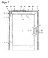
- the exemplary embodiment in FIG. 1 shows a single-wing revolving door in a building with an overhead door drive 3 of conventional design.
- the door drive 3 is a hydraulic swing door drive 3, with which the door is opened by a motor or a motor and is closed hydraulically damped under the action of a closing spring. It is constructed as a hydraulically damped door closer with closing spring, combined with an electro-hydraulic opener drive with electric motor and pump (not shown).
- the door closer and the ⁇ ffnerantrieb are integrated in a unit in a housing 31 which is mounted near the upper horizontal edge on the door panel 1.
- the output shaft 32 of the revolving door drive 3 is rotatably connected in a known manner with a sliding arm 33.
- the sliding arm 33 has at its free end a slider as a guide element, which is guided in the slide rail 34 at the upper vertical spar of the stationary frame 2. In this case, the free end of the sliding arm 33 engages the wing 1 outside the axis of rotation of the wing 1.
- the door drive 3 on the frame 2 is mounted and the slide 34 on the door panel 1.
- the power transmitting linkage also designed as a scissor arm and with his be free end in a stationary pivot bearing or supported on the wing.
- the door 1 is at its left vertical Edge about two hinges on the left vertical spar of the frame 2 rotatable hinged.
- the swing door drive 3 is connected to an electrical supply and Control line 38 connected, which from the left side portion 37 of the revolving door drive 3 out to a supply terminal 12 on the door frame 2 becomes.
- the door 1 has a lock area 5 shown in dashed lines with a Lock catch 51 on. The operation of the lock latch 51 takes place by Push or pull on the door handle 13.
- the control of the door drive 3 to open the door is carried out according to the invention via a arranged in the region of the handle 13 sensor which with the not is shown connected door control.
- the door opens as a result of the sensor operation initially under the action of the engine and the pump, which hydraulic medium in the circuit of the hydraulic door closer pumps, causing the piston moved and the spring is tensioned.
- the subsequent closing process takes place solely by utilizing the stored in the closing spring Energy.
- a so-called servo operation can also be selected be in which the door 1 by the support of the engine opened manually with or without reduced opening resistance of the closing spring can be.
- FIG 2 shows a detailed view of the door handles 13 in Figure 1 on both sides of the door leaf 1, but omitting the door leaf 1 itself.
- the two handles 13 are designed as bow handles and each pivotally mounted about a vertical axis on the handle fitting 14. The pivoting direction of both handles 13 is opposite to each other.
- the handle 13 must be actuated respectively in the opening direction of the door, so pulling on one side of the door and pressing on the other side of the door.
- the two handle fittings 14 are connected via two through the door leaf 1 cross-glands 16 and thus fixed on the door panel 1.
- the between two handle fittings 14 rotatably mounted about a horizontal axis handle bar 17 is used to actuate the latch 51.
- the lock not shown, in its structure of DE 43 17 564 C2 correspond or be constructed as another conventional lock, as in the prospectus K87 5187 E of the company Fritz Fuss GmbH & Co is described.
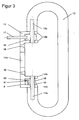
- the handle 13 shown in cross-section in Figure 3 corresponds to that of Figures 1 and 2. It serves as a control handle for the latch 51 in the lock area 5 of the door leaf 1 and as a drive element for the door drive shown in Figure 1 3.
- the plate-shaped handle fitting 14 contributes its upper and its lower end in each case two closely spaced horizontal leg 14b at a small distance.
- Two square pins 13 a are rotatably mounted at the upper and lower end of the handle fitting 14 about a vertical axis within the legs 14 b, wherein they pass through the legs 14.
- the square pins 13a serve as a mounting option and as a rotation axis for the door handle 13.
- the handle fitting 14 has a central recess for by passing the lock cylinder.
- a Gear 15 is arranged, which is a rotational movement of the bracket and the square pin 13a converts into a rotational movement of the presser bar 17.
- the Drükkerstab 17 passes through the handle fitting 14 between the two legs 14b and is thus in communication with the transmission 15.
- a rotary movement of the drill rod 17 leads in a known manner to a mechanical actuation of Lock catch 51, whereupon the door can be opened.
- an abutment 18 rotatably connected to the square pin 13a.
- a thigh spring supports on the one hand on this abutment 18 and on the other hand on the handle fitting 14 off.
- a sensor arrangement which with mechanical operation of the bow handle 13 and the so connected unlocking the latch 51 at the same time the door drive 3 to the motor or motor-assisted opening of the door activates.
- the sensor arrangement it is preferably a microswitch 6, which between the two legs 14 b is arranged and its switching contact 61 in the trajectory of a switching flag 62 protrudes.
- the switching flag 62 is on the Abutment 18 arranged pointing radially outward.
- the one required to trigger the signal Switching can be achieved by appropriate positioning of the microswitch 6 and the switch flag 62 regulate.
- the switching signal is the door drive. 3 fed, which then the motor to the motor or motor assisted Opening the door turns on.
- the transmission of the switching signal can thereby both via a cable feed within the door leaf 1 and via radio respectively.
- the switching device according to the invention is also suitable for use in FR doors and RWS doors.
- FIG. 4 shows an alternative embodiment of a door handle 13 for generating a drive signal for the electrical control of a revolving door drive 3.
- the door handle 13 is not here the operation of a latch 51.
- a base 4 is provided with a screw 16 on the door leaf. 1 fastened, wherein the diameter of the base 4 is smaller than the inner diameter of the tubular handle 13.
- the base 4 in turn carries a cap 43 on which the tubular handle 13 is mounted.
- the handle 13 is pushed from the front onto the attachment 43 and fixed there with a cylindrical pin 44 extending transversely through the handle 13.
- Between Sokkel 4 and article 43 is an elastic body or a spring element, which on the one hand pedestal 4 and 43 attachment firmly together, but still allows a certain mobility of base 4 and 43 attachment to each other.
- two microswitches 6 are arranged or integrated.
- the door facing the end of the Handle 13 at a short distance to both the door and the switch contacts 61st the microswitch 6.
- the door By touching the handle 13 by a person who the Door wants to happen, takes place by the forces occurring a corresponding deformation the elastic intermediate piece.
- a drive signal is passed to the door drive 3.
- the door is then opened by a motor or the manual opening process is supported in servo operation.
- Such an embodiment without mechanical transmission links is also suitable to parallel to the control of the motor and an electric actuator the lock catch 51 to effect.
- the signal of the microswitch 6 can be used for any purpose.
- the actuation of the microswitch 6 is not effected by a pivoting movement of the handle 13, but by pressing the handle 13 in the direction of the door leaf 1.
- a base 4 is also on the door panel 1 by a screw 16th attached.
- the attachment 43 surrounds the base 4 and is displaceably guided in the axial direction on this.
- a plate spring 45 or compression spring or even an elastic body is between base 4 and 43 essay.
- a guide pin 46 is anchored with its one end 46 a in the article 43 and with its other end 46b through a hole in the base 4 guided.
- a widened socket-side end 46b of the guide pin 46 prevents slipping out of the hole.
- it is a sliding down the Attachment 43 prevents the base 4.
- a microswitch 6 is arranged in the base 4 in below the widened End.
- Figure 6 finally shows a revolving door according to Figure 1 with a conventional doorknob in place of a pivotable bow-shaped handle 13 for actuating the lock latch 51 and for controlling the motor.
- the invention is independent of the design of the door handle 13. It may be handles or even conventional latches.
- the handles 13 may be tubular or plate-shaped.
- the handles 13 may be pivotable, rotatable or designed to be pulled or pressed perpendicular to the wing plane.
- Ser use of the device according to the invention is not on the illustrated Embodiments limited.
- a microswitch 6 can also be a Reed switch or any other type of switching contact 61 are used.
- Around To reduce the size further, can also be connected to the door base part and connected to the handle 13 essay 43 electrically conductive be. Upon contact, an electrical signal is generated immediately, which used to control the drive.
- the transmitter is fixed in the wing 1, preferably in the region of the door handle 13 or in the door handle 13 itself.
- the arrangement the sender also be fixed in the frame 2.
- the receiver is preferably in the region of the drive 3, preferably in or on the drive housing 31, arranged.
- the power supply of the transmitter and / or the receiver can by a or multiple accumulators.
- the accumulator for the supply of the transmitter is here in the wing 1 fixed, preferably fixedly arranged in the door handle 13, wherein this accumulator in the range of the transmitter as a unit with the transmitter can be arranged.
- the drive signal as a pulse, preferably one-time pulse, or be designed as a permanent signal.
- the drive may be on as long as the drive signal is present, i. when you release the door handle or the like, the process of motor or motor assisted opening and / or closing the revolving door leaf interrupted or subsequently only the closing process to the closed position supported by motor or motor or carried out automatically via a closing spring.
- the process of the motor or motor-assisted opening and / or closing the revolving door leaf is triggered by the drive signal, preferably by a pulse, and the door then a whole opening movement / closing motion motor or automatically executes.
Landscapes
- Power-Operated Mechanisms For Wings (AREA)
Description
- Figur 1
- eine Frontansicht einer Drehtür mit einem Drehtürantrieb und einer Schaltvorrichtung;
- Figur 2
- eine Detaildarstellung der Türgriffe in Figur 1 beiderseits der Tür unter Weglassung des Türblattes;
- Figur 3
- eine Darstellung eines Türgriffes in Figur 2 im Querschnitt;
- Figur 4
- eine Darstellung eines alternativen Ausführungsbeispieles im Querschnitt;
- Figur 5
- eine Darstellung eines abgewandelten Ausführungsbeispieles im Querschnitt;
- Figur 6
- eine Frontansicht einer Drehtür gemäß Figur 1 mit einer Türklinke.
- 1
- Türblatt, Türflügel
- 11
- Türband
- 12
- Versorgungsanschluß
- 13
- Türgriff, Griff
- 13a
- Vierkantstift
- 14
- Griffbeschlag
- 14a
- Ausnehmung
- 14b
- horizontaler Schenkel
- 15
- Getriebe
- 16
- Verschraubung
- 17
- Drückerstab
- 18
- Widerlager
- 19
- Rückstellfeder
- 2
- Rahmen, Türrahmen
- 3
- Türantrieb
- 31
- Gehäuse
- 32
- Abtriebswelle
- 33
- Gleitarm
- 34
- Gleitschiene
- 36
- Abdeckhaube
- 37
- Seitenteil
- 38
- Steuerleitung
- 4
- Sockel
- 41
- Schraubbefestigung
- 42
- Elastikkörper
- 43
- Aufsatz
- 44
- Zylinderstift
- 45
- Tellerfeder
- 46
- Führungsstift
- 46a
- verschraubtes Ende
- 46b
- verbreitertes Ende
- 5
- Schloßbereich
- 51
- Schloßfalle
- 6
- Mikroschalter
- 61
- Schaltkontakt
- 62
- Schaltfahne
Claims (25)
- Türantrieb (3) für eine Drehflügeltür, mit einem elektrischen Motor zum motorischen oder motorisch unterstützten Öffnen und/oder Schließen eines Türflügels (1), welcher eine Schließerfeder zum selbsttätigen Schließen und einen elektrischen Motor zum Beaufschlagen der Schließerfeder aufweist, um den Türflügel (1) ohne oder mit reduziertem Öffnungswiderstand der Schließerfeder von Hand öffnen zu können,
und mit einer ein elektrisches Signal abgebenden Schaltvorrichtung (6) zur Betätigung des elektrischen Motors,
dadurch gekennzeichnet, dass die Schaltvorrichtung (6) zur Betätigung des elektrischen Motors am Türflügel (1) fest oder an einem am Türflügel (1) angeordneten Türgriff (13) fest angeordnet ist, so dass die Betätigung der Schaltvorrichtung (6) durch eine Relativbewegung des Türgriffs (13) gegenüber dem Türflügel (1) erfolgt. - Vorrichtung nach Anspruch 1 , dadurch gekennzeichnet, dass die Schaltvorrichtung (6) einen Sensor aufweist
- Vorrichtung nach Anspruch 1 , dadurch gekennzeichnet, dass die Schaltvorrichtung (6) elektrisch leitende Bereiche aufweist, welche bei gegenseitiger Berührung abhängig von der Betätigung des Türgriffes (13) ein Steuersignal erzeugen.
- Vorrichtung nach Anspruch 1, dadurch gekennzeichnet, dass der Türflügel (1) einen Schlossbereich (5) mit Schlossfalle (51) aufweist und der Türgriff (13) im Schlossbereich (5) angeordnet ist und/oder diesen durchgreift, wobei der Türgriff (13) die am Türflügel (1) angeordnete Schlossfalle (51) betätigt.
- Vorrichtung nach Anspruch 4 , dadurch gekennzeichnet, dass der Schlossbereich (5) einen durch den Schlossbereich (5) hindurchgreifenden Drückerstab (17) aufweist, und die Schaltvorrichtung (6) im Drehbereich des Drückerstabes (17) derart angeordnet ist, dass sie zum Schaltvorgang mit dem Drückerstab (17) zusammenwirkt.
- Vorrichtung nach Anspruch 5 , dadurch gekennzeichnet, dass der Türgriff (13) ein flügelfestes Beschlagteil (14) aufweist und die Schaltvorrichtung (6) an dem flügelfesten Beschlagteil (14) im Bereich einer Bewegungsachse des Türgriffes (13), derart angeordnet ist, dass sie zum Schaltvorgang mit dem Türgriff (13) mittelbar oder unmittelbar zusammenwirkt.
- Vorrichtung nach Anspruch 1 , dadurch gekennzeichnet, dass die Schaltvorrichtung (6) auf dem Türflügel (1) oder einem mit dem Türflügel (1) verbundenen Teil (4) angeordnet ist, und zum Schaltvorgang unmittelbar mit dem Türgriff (13) zusammenwirkt, oder umgekehrt.
- Vorrichtung nach Anspruch 1. dadurch gekennzeichnet, dass die Schaltvorrichtung (6) innerhalb des Türgriffes (13) angeordnet ist.
- Vorrichtung nach Anspruch 8 , dadurch gekennzeichnet, dass zwischen dem Türflügel (1) oder dem damit verbundenen Teil (4) und dem Türgriff (13) ein Zwischenglied angeordnet ist, welches eine Relativbewegung zwischen Türgriff (13) und Türflügel (1) ermöglicht und/oder begrenzt.
- Vorrichtung nach Anspruch 9 , dadurch gekennzeichnet, dass es sich bei dem Zwischenglied um einen flexiblen Elastikkörper (42) handelt.
- Vorrichtung nach Anspruch 1 , dadurch gekennzeichnet, dass der Türgriff (13) drückbar, ziehbar, drehbar oder schwenkbar ausgebildet ist.
- Vorrichtung nach Anspruch 11 , dadurch gekennzeichnet, dass der Schaltweg und/oder Schaltpunkt der Schaltvorrichtung (6) einstellbar ist.
- Vorrichtung nach Anspruch 1 , dadurch gekennzeichnet, dass der elektrische Motor am ortsfesten Türrahmen (2) oberhalb des Flügels (1) oder am Türflügel angeordnet ist, wobei der Motor mit seinem Abtriebsglied mit dem Flügel (1) bzw. dem ortsfesten Türrahmen (2) über ein kraftübertragendes Gestänge (33) verbunden ist, dessen freies Ende am Flügel (1) bzw. am ortsfesten Türrahmen (2) außerhalb der Drehachse des Flügels (1) angreift.
- Vorrichtung nach Anspruch 1 , dadurch gekennzeichnet, dass die Schaltvorrichtung (6) mit dem Motor über ein elektrisches Kabel und/oder einen Schleifkontakt und/oder über Funk verbunden ist.
- Vorrichtung nach Anspruch 1 , dadurch gekennzeichnet, dass die Schaltvorrichtung (6) einen Sender aufweist oder mit einem solchen Sender verbunden ist oder zusammenwirkt, und dass ein Empfänger vorgesehen ist, der mit dem Motor oder einer Steuerungsvorrichtung des Motors verbunden ist oder zusammenwirkt.
- Vorrichtung nach Anspruch 15 , dadurch gekennzeichnet, dass der Sender im Türflügel (1) fest angeordnet ist.
- Vorrichtung nach Anspruch 15 , dadurch gekennzeichnet, dass der Sender im Bereich des Türgriffs (13) fest angeordnet ist.
- Vorrichtung nach Anspruch 1 5, dadurch gekennzeichnet, dass der Empfänger im Türantrieb (3) oder in unmittelbarer Nähe des Türantriebs (3) angeordnet ist.
- Vorrichtung nach Anspruch 15 , dadurch gekennzeichnet, dass der Sender und/oder der Empfänger von einem oder mehreren Akkumulatoren mit Energie versorgt werden.
- Vorrichtung nach Anspruch 19 , dadurch gekennzeichnet, dass der Akkumulator zur Versorgung des Senders im Blendrahmen fest oder im Flügel fest oder im Türgriff fest angeordnet ist.
- Vorrichtung nach Anspruch 19, dadurch gekennzeichnet, dass der Akkumulator zur Versorgung des Senders im Bereich des Senders angeordnet ist.
- Vorrichtung nach Anspruch 1, dadurch gekennzeichnet, dass das Signal zur Ansteuerung als Impuls ausgebildet ist.
- Vorrichtung nach Anspruch 1 , dadurch gekennzeichnet, dass das Signal zu Ansteuerung als Permanent-Signal ausgebildet ist.
- Vorrichtung nach Anspruch 1 , dadurch gekennzeichnet, dass der Motor zum motorischen oder motorisch unterstützten Öffnen und/oder Schließen des Türflügels (1) nur so lange eingeschaltet ist, wie das Signal zur Ansteuerung anliegt.
- Vorrichtung nach Anspruch 22 , dadurch gekennzeichnet, dass der Motor zum motorischen oder motorisch unterstützten Öffnen und/oder Schließen des Türflügels (1) über einen Impuls eingeschaltet wird und eingeschaltet bleibt, so lange bis der Türflügel (1) eine gesamte Öffnungsbewegung/Schließbewegung ausgeführt hat.
Applications Claiming Priority (2)
| Application Number | Priority Date | Filing Date | Title |
|---|---|---|---|
| DE19712369A DE19712369A1 (de) | 1997-03-25 | 1997-03-25 | Türantrieb mit Schaltvorrichtung |
| DE19712369 | 1997-03-25 |
Publications (3)
| Publication Number | Publication Date |
|---|---|
| EP0867588A2 EP0867588A2 (de) | 1998-09-30 |
| EP0867588A3 EP0867588A3 (de) | 2001-04-18 |
| EP0867588B1 true EP0867588B1 (de) | 2005-11-02 |
Family
ID=7824478
Family Applications (1)
| Application Number | Title | Priority Date | Filing Date |
|---|---|---|---|
| EP98105388A Expired - Lifetime EP0867588B1 (de) | 1997-03-25 | 1998-03-25 | Türantrieb mit Schaltvorrichtung |
Country Status (4)
| Country | Link |
|---|---|
| EP (1) | EP0867588B1 (de) |
| AT (1) | ATE308656T1 (de) |
| DE (2) | DE19712369A1 (de) |
| ES (1) | ES2247645T3 (de) |
Cited By (1)
| Publication number | Priority date | Publication date | Assignee | Title |
|---|---|---|---|---|
| CN111550149A (zh) * | 2020-05-09 | 2020-08-18 | 陕西飞机工业(集团)有限公司 | 一种重复作动的武器舱门电气信号转换装置 |
Families Citing this family (4)
| Publication number | Priority date | Publication date | Assignee | Title |
|---|---|---|---|---|
| DE19944051A1 (de) * | 1999-09-14 | 2001-03-15 | Wilke Heinrich Hewi Gmbh | Verriegelungsvorrichtung |
| DE102008040897A1 (de) * | 2008-07-31 | 2010-02-04 | Aug. Winkhaus Gmbh & Co. Kg | Treibstangenbeschlag für ein Fenster oder für eine Fenstertür eines Gebäudes und Verfahren zum Ansteuern eines Treibstangenbeschlages für ein Fenster oder für eine Fenstertür eines Gebäudes |
| CN112854945B (zh) * | 2021-02-06 | 2021-12-10 | 哈尔滨贰零贰壹科技有限公司 | 一种自动门 |
| DE102023210163A1 (de) * | 2023-10-17 | 2025-04-17 | Geze Gmbh | Türsystem |
Family Cites Families (10)
| Publication number | Priority date | Publication date | Assignee | Title |
|---|---|---|---|---|
| GB191317942A (en) * | 1912-04-09 | 1914-02-12 | Arno Hoehne | Improvements in or relating to Means for Opening and Closing Doors. |
| US4010572A (en) * | 1975-06-02 | 1977-03-08 | C. Hager & Sons Hinge Manufacturing Company | Door closer having means to neutralize the door closing force exerted thereby |
| DE3202966A1 (de) | 1982-01-29 | 1983-08-11 | Geze Gmbh, 7250 Leonberg | Elektrohydraulische antriebseinheit fuer fluegel von tueren o.dgl. |
| DE3500062A1 (de) * | 1985-01-03 | 1986-07-10 | Uwe Dipl.-Ing. 3300 Braunschweig Kayser-Herold | Servomotorischer tuerverschluss |
| AT394415B (de) * | 1989-11-27 | 1992-03-25 | Jenbacher Werke Ag | Einrichtung zum verschliessen bzw. oeffnen einer tuer |
| DE4317564C2 (de) | 1993-05-26 | 1995-05-11 | Fuss Fritz Gmbh & Co | Türöffner mit einer verriegelbaren, schwenkbaren Falle |
| DE4323150B4 (de) | 1993-07-10 | 2004-09-23 | Geze Gmbh | Drehtürantrieb |
| DE4445366A1 (de) * | 1994-12-20 | 1996-06-27 | Croon Lucke Maschinen | Fenster |
| DE19518396B4 (de) | 1995-05-19 | 2005-05-12 | Geze Gmbh | Türantrieb für einen beidseitig begehbaren Drehtürflügel |
| DE29603917U1 (de) | 1996-03-02 | 1996-05-09 | Buchhalter, Thomas, 53859 Niederkassel | Überwachungseinrichtung |
-
1997
- 1997-03-25 DE DE19712369A patent/DE19712369A1/de not_active Withdrawn
-
1998
- 1998-03-25 AT AT98105388T patent/ATE308656T1/de active
- 1998-03-25 EP EP98105388A patent/EP0867588B1/de not_active Expired - Lifetime
- 1998-03-25 ES ES98105388T patent/ES2247645T3/es not_active Expired - Lifetime
- 1998-03-25 DE DE59813149T patent/DE59813149D1/de not_active Expired - Lifetime
Cited By (1)
| Publication number | Priority date | Publication date | Assignee | Title |
|---|---|---|---|---|
| CN111550149A (zh) * | 2020-05-09 | 2020-08-18 | 陕西飞机工业(集团)有限公司 | 一种重复作动的武器舱门电气信号转换装置 |
Also Published As
| Publication number | Publication date |
|---|---|
| EP0867588A3 (de) | 2001-04-18 |
| DE19712369A1 (de) | 1998-10-01 |
| ATE308656T1 (de) | 2005-11-15 |
| DE59813149D1 (de) | 2005-12-08 |
| ES2247645T3 (es) | 2006-03-01 |
| EP0867588A2 (de) | 1998-09-30 |
Similar Documents
| Publication | Publication Date | Title |
|---|---|---|
| DE112009000529B4 (de) | Schloss mit drehbarer Sperrklinke | |
| DE69909204T2 (de) | Verbessertes elektrisches Schloss für eine Kraftfahrzeugtür | |
| DE2847589C2 (de) | ||
| EP2459824B1 (de) | Zuziehvorrichtung für eine tür | |
| DE4427213C5 (de) | Türschloss für ein Kraftfahrzeug | |
| EP1700284B1 (de) | Fenster und handhabe für ein fenster | |
| EP1092829B1 (de) | Antriebseinrichtung für eine Tür | |
| EP0942135B1 (de) | Verriegelungseinrichtung | |
| WO2018137839A1 (de) | Türgriffanordnung für eine fahrzeugtür | |
| EP3219886B1 (de) | Anti-panikdruckstange mit antriebseinrichtung | |
| WO2006074967A1 (de) | Vorrichtung zum erfassen der position einer betätigungshandhabe und/oder eines fensterflügels, eines türblatts o.dgl. | |
| DE10207630B4 (de) | Schloss mit Fernbetätigung | |
| DE3520932C2 (de) | Türschloßanordnung | |
| EP1088950A2 (de) | Verriegelungsvorrichtung | |
| DE19547724A1 (de) | Schloß, insbesondere für Kraftfahrzeugtüren | |
| EP2765261A2 (de) | Schließvorrichtung eines Gebäudes | |
| EP0867588A2 (de) | Türantrieb mit Schaltvorrichtung | |
| WO2005005757A1 (de) | Kraftfahrzeugtürverschluss | |
| DE69907356T2 (de) | Vereinfachtes Schloss für eine Kraftfahrzeugtür | |
| DE102004030902A1 (de) | Kraftfahrzeugtürverschluss | |
| DE10060547B4 (de) | Vorrichtung zur Betätigung eines Verschlusses an einer Tür, Klappe o. dgl., insbesondere bei einem Fahrzeug | |
| DE8704036U1 (de) | Türschloß mit Verriegelungselement und Hilfsfalle | |
| WO2020058363A1 (de) | Möbelstück mit öffner | |
| DE19532263B4 (de) | Vorrichtung zur Schließfolgeregelung für zweiflügelige Türen | |
| EP0258582A2 (de) | Elektromotorisches Stellelement für eine Zentralverriegelungsanlage von Kraftfahrzeugen |
Legal Events
| Date | Code | Title | Description |
|---|---|---|---|
| PUAI | Public reference made under article 153(3) epc to a published international application that has entered the european phase |
Free format text: ORIGINAL CODE: 0009012 |
|
| AK | Designated contracting states |
Kind code of ref document: A2 Designated state(s): AT CH DE ES FR GB IT LI SE |
|
| AX | Request for extension of the european patent |
Free format text: AL;LT;LV;MK;RO;SI |
|
| RAP1 | Party data changed (applicant data changed or rights of an application transferred) |
Owner name: GEZE GMBH |
|
| RAP3 | Party data changed (applicant data changed or rights of an application transferred) |
Owner name: GEZE GMBH |
|
| PUAL | Search report despatched |
Free format text: ORIGINAL CODE: 0009013 |
|
| AK | Designated contracting states |
Kind code of ref document: A3 Designated state(s): AT BE CH DE DK ES FI FR GB GR IE IT LI LU MC NL PT SE |
|
| AX | Request for extension of the european patent |
Free format text: AL;LT;LV;MK;RO;SI |
|
| 17P | Request for examination filed |
Effective date: 20011016 |
|
| AKX | Designation fees paid |
Free format text: AT BE CH DE DK ES FI FR LI |
|
| RBV | Designated contracting states (corrected) |
Designated state(s): AT CH DE ES FR GB IT LI SE |
|
| 17Q | First examination report despatched |
Effective date: 20040528 |
|
| GRAP | Despatch of communication of intention to grant a patent |
Free format text: ORIGINAL CODE: EPIDOSNIGR1 |
|
| GRAS | Grant fee paid |
Free format text: ORIGINAL CODE: EPIDOSNIGR3 |
|
| GRAA | (expected) grant |
Free format text: ORIGINAL CODE: 0009210 |
|
| AK | Designated contracting states |
Kind code of ref document: B1 Designated state(s): AT CH DE ES FR GB IT LI SE |
|
| REG | Reference to a national code |
Ref country code: GB Ref legal event code: FG4D Free format text: NOT ENGLISH |
|
| REG | Reference to a national code |
Ref country code: CH Ref legal event code: NV Representative=s name: E. BLUM & CO. PATENTANWAELTE Ref country code: CH Ref legal event code: EP |
|
| GBT | Gb: translation of ep patent filed (gb section 77(6)(a)/1977) |
Effective date: 20051102 |
|
| REF | Corresponds to: |
Ref document number: 59813149 Country of ref document: DE Date of ref document: 20051208 Kind code of ref document: P |
|
| REG | Reference to a national code |
Ref country code: SE Ref legal event code: TRGR |
|
| REG | Reference to a national code |
Ref country code: ES Ref legal event code: FG2A Ref document number: 2247645 Country of ref document: ES Kind code of ref document: T3 |
|
| ET | Fr: translation filed | ||
| PLBE | No opposition filed within time limit |
Free format text: ORIGINAL CODE: 0009261 |
|
| STAA | Information on the status of an ep patent application or granted ep patent |
Free format text: STATUS: NO OPPOSITION FILED WITHIN TIME LIMIT |
|
| 26N | No opposition filed |
Effective date: 20060803 |
|
| REG | Reference to a national code |
Ref country code: CH Ref legal event code: PFA Owner name: GEZE GMBH Free format text: GEZE GMBH#REINHOLD-VOESTER-STRASSE 21-29#71229 LEONBERG (DE) -TRANSFER TO- GEZE GMBH#REINHOLD-VOESTER-STRASSE 21-29#71229 LEONBERG (DE) |
|
| PGFP | Annual fee paid to national office [announced via postgrant information from national office to epo] |
Ref country code: ES Payment date: 20130326 Year of fee payment: 16 |
|
| PGFP | Annual fee paid to national office [announced via postgrant information from national office to epo] |
Ref country code: CH Payment date: 20140319 Year of fee payment: 17 Ref country code: SE Payment date: 20140319 Year of fee payment: 17 |
|
| PGFP | Annual fee paid to national office [announced via postgrant information from national office to epo] |
Ref country code: FR Payment date: 20140319 Year of fee payment: 17 Ref country code: IT Payment date: 20140325 Year of fee payment: 17 Ref country code: AT Payment date: 20140312 Year of fee payment: 17 |
|
| PGFP | Annual fee paid to national office [announced via postgrant information from national office to epo] |
Ref country code: GB Payment date: 20140319 Year of fee payment: 17 |
|
| REG | Reference to a national code |
Ref country code: CH Ref legal event code: PL |
|
| REG | Reference to a national code |
Ref country code: AT Ref legal event code: MM01 Ref document number: 308656 Country of ref document: AT Kind code of ref document: T Effective date: 20150325 |
|
| GBPC | Gb: european patent ceased through non-payment of renewal fee |
Effective date: 20150325 |
|
| PG25 | Lapsed in a contracting state [announced via postgrant information from national office to epo] |
Ref country code: SE Free format text: LAPSE BECAUSE OF NON-PAYMENT OF DUE FEES Effective date: 20150326 |
|
| REG | Reference to a national code |
Ref country code: SE Ref legal event code: EUG |
|
| PG25 | Lapsed in a contracting state [announced via postgrant information from national office to epo] |
Ref country code: IT Free format text: LAPSE BECAUSE OF NON-PAYMENT OF DUE FEES Effective date: 20150325 |
|
| REG | Reference to a national code |
Ref country code: FR Ref legal event code: ST Effective date: 20151130 |
|
| PG25 | Lapsed in a contracting state [announced via postgrant information from national office to epo] |
Ref country code: CH Free format text: LAPSE BECAUSE OF NON-PAYMENT OF DUE FEES Effective date: 20150331 Ref country code: LI Free format text: LAPSE BECAUSE OF NON-PAYMENT OF DUE FEES Effective date: 20150331 Ref country code: GB Free format text: LAPSE BECAUSE OF NON-PAYMENT OF DUE FEES Effective date: 20150325 |
|
| PG25 | Lapsed in a contracting state [announced via postgrant information from national office to epo] |
Ref country code: AT Free format text: LAPSE BECAUSE OF NON-PAYMENT OF DUE FEES Effective date: 20150325 Ref country code: FR Free format text: LAPSE BECAUSE OF NON-PAYMENT OF DUE FEES Effective date: 20150331 |
|
| REG | Reference to a national code |
Ref country code: ES Ref legal event code: FD2A Effective date: 20160428 |
|
| PG25 | Lapsed in a contracting state [announced via postgrant information from national office to epo] |
Ref country code: ES Free format text: LAPSE BECAUSE OF NON-PAYMENT OF DUE FEES Effective date: 20150326 |
|
| PGFP | Annual fee paid to national office [announced via postgrant information from national office to epo] |
Ref country code: DE Payment date: 20170331 Year of fee payment: 20 |
|
| REG | Reference to a national code |
Ref country code: DE Ref legal event code: R071 Ref document number: 59813149 Country of ref document: DE |