EP0866300B1 - Getriebeölkühler - Google Patents
Getriebeölkühler Download PDFInfo
- Publication number
- EP0866300B1 EP0866300B1 EP98104854A EP98104854A EP0866300B1 EP 0866300 B1 EP0866300 B1 EP 0866300B1 EP 98104854 A EP98104854 A EP 98104854A EP 98104854 A EP98104854 A EP 98104854A EP 0866300 B1 EP0866300 B1 EP 0866300B1
- Authority
- EP
- European Patent Office
- Prior art keywords
- oil cooler
- transmission oil
- ring
- threaded ring
- sidewall
- Prior art date
- Legal status (The legal status is an assumption and is not a legal conclusion. Google has not performed a legal analysis and makes no representation as to the accuracy of the status listed.)
- Expired - Lifetime
Links
- 230000005540 biological transmission Effects 0.000 title claims description 31
- 238000007789 sealing Methods 0.000 claims description 28
- XLYOFNOQVPJJNP-UHFFFAOYSA-N water Substances O XLYOFNOQVPJJNP-UHFFFAOYSA-N 0.000 claims description 20
- 239000002826 coolant Substances 0.000 claims description 6
- 230000002093 peripheral effect Effects 0.000 claims description 2
- 238000010348 incorporation Methods 0.000 claims 1
- 230000000284 resting effect Effects 0.000 claims 1
- 239000003921 oil Substances 0.000 description 30
- 241000538562 Banjos Species 0.000 description 3
- 238000001816 cooling Methods 0.000 description 3
- 238000013461 design Methods 0.000 description 3
- 238000011161 development Methods 0.000 description 3
- 238000003780 insertion Methods 0.000 description 3
- 230000037431 insertion Effects 0.000 description 3
- 238000009434 installation Methods 0.000 description 3
- 238000000034 method Methods 0.000 description 3
- 125000006850 spacer group Chemical group 0.000 description 2
- 229910052782 aluminium Inorganic materials 0.000 description 1
- XAGFODPZIPBFFR-UHFFFAOYSA-N aluminium Chemical compound [Al] XAGFODPZIPBFFR-UHFFFAOYSA-N 0.000 description 1
- 238000013459 approach Methods 0.000 description 1
- 238000010276 construction Methods 0.000 description 1
- 239000000498 cooling water Substances 0.000 description 1
- 230000008878 coupling Effects 0.000 description 1
- 238000010168 coupling process Methods 0.000 description 1
- 238000005859 coupling reaction Methods 0.000 description 1
- 239000013013 elastic material Substances 0.000 description 1
- 239000012208 gear oil Substances 0.000 description 1
- 238000004519 manufacturing process Methods 0.000 description 1
- 229910052751 metal Inorganic materials 0.000 description 1
- 239000002184 metal Substances 0.000 description 1
- 238000005192 partition Methods 0.000 description 1
Images

Classifications
-
- F—MECHANICAL ENGINEERING; LIGHTING; HEATING; WEAPONS; BLASTING
- F28—HEAT EXCHANGE IN GENERAL
- F28F—DETAILS OF HEAT-EXCHANGE AND HEAT-TRANSFER APPARATUS, OF GENERAL APPLICATION
- F28F9/00—Casings; Header boxes; Auxiliary supports for elements; Auxiliary members within casings
- F28F9/007—Auxiliary supports for elements
- F28F9/0075—Supports for plates or plate assemblies
-
- F—MECHANICAL ENGINEERING; LIGHTING; HEATING; WEAPONS; BLASTING
- F01—MACHINES OR ENGINES IN GENERAL; ENGINE PLANTS IN GENERAL; STEAM ENGINES
- F01M—LUBRICATING OF MACHINES OR ENGINES IN GENERAL; LUBRICATING INTERNAL COMBUSTION ENGINES; CRANKCASE VENTILATING
- F01M5/00—Heating, cooling, or controlling temperature of lubricant; Lubrication means facilitating engine starting
- F01M5/002—Cooling
-
- F—MECHANICAL ENGINEERING; LIGHTING; HEATING; WEAPONS; BLASTING
- F16—ENGINEERING ELEMENTS AND UNITS; GENERAL MEASURES FOR PRODUCING AND MAINTAINING EFFECTIVE FUNCTIONING OF MACHINES OR INSTALLATIONS; THERMAL INSULATION IN GENERAL
- F16H—GEARING
- F16H57/00—General details of gearing
- F16H57/04—Features relating to lubrication or cooling or heating
-
- F—MECHANICAL ENGINEERING; LIGHTING; HEATING; WEAPONS; BLASTING
- F28—HEAT EXCHANGE IN GENERAL
- F28D—HEAT-EXCHANGE APPARATUS, NOT PROVIDED FOR IN ANOTHER SUBCLASS, IN WHICH THE HEAT-EXCHANGE MEDIA DO NOT COME INTO DIRECT CONTACT
- F28D9/00—Heat-exchange apparatus having stationary plate-like or laminated conduit assemblies for both heat-exchange media, the media being in contact with different sides of a conduit wall
- F28D9/0031—Heat-exchange apparatus having stationary plate-like or laminated conduit assemblies for both heat-exchange media, the media being in contact with different sides of a conduit wall the conduits for one heat-exchange medium being formed by paired plates touching each other
- F28D9/0043—Heat-exchange apparatus having stationary plate-like or laminated conduit assemblies for both heat-exchange media, the media being in contact with different sides of a conduit wall the conduits for one heat-exchange medium being formed by paired plates touching each other the plates having openings therein for circulation of at least one heat-exchange medium from one conduit to another
-
- F—MECHANICAL ENGINEERING; LIGHTING; HEATING; WEAPONS; BLASTING
- F28—HEAT EXCHANGE IN GENERAL
- F28D—HEAT-EXCHANGE APPARATUS, NOT PROVIDED FOR IN ANOTHER SUBCLASS, IN WHICH THE HEAT-EXCHANGE MEDIA DO NOT COME INTO DIRECT CONTACT
- F28D9/00—Heat-exchange apparatus having stationary plate-like or laminated conduit assemblies for both heat-exchange media, the media being in contact with different sides of a conduit wall
- F28D9/0062—Heat-exchange apparatus having stationary plate-like or laminated conduit assemblies for both heat-exchange media, the media being in contact with different sides of a conduit wall the conduits for one heat-exchange medium being formed by spaced plates with inserted elements
- F28D9/0075—Heat-exchange apparatus having stationary plate-like or laminated conduit assemblies for both heat-exchange media, the media being in contact with different sides of a conduit wall the conduits for one heat-exchange medium being formed by spaced plates with inserted elements the plates having openings therein for circulation of the heat-exchange medium from one conduit to another
-
- F—MECHANICAL ENGINEERING; LIGHTING; HEATING; WEAPONS; BLASTING
- F28—HEAT EXCHANGE IN GENERAL
- F28F—DETAILS OF HEAT-EXCHANGE AND HEAT-TRANSFER APPARATUS, OF GENERAL APPLICATION
- F28F9/00—Casings; Header boxes; Auxiliary supports for elements; Auxiliary members within casings
- F28F9/02—Header boxes; End plates
- F28F9/0234—Header boxes; End plates having a second heat exchanger disposed there within, e.g. oil cooler
-
- F—MECHANICAL ENGINEERING; LIGHTING; HEATING; WEAPONS; BLASTING
- F28—HEAT EXCHANGE IN GENERAL
- F28F—DETAILS OF HEAT-EXCHANGE AND HEAT-TRANSFER APPARATUS, OF GENERAL APPLICATION
- F28F9/00—Casings; Header boxes; Auxiliary supports for elements; Auxiliary members within casings
- F28F9/02—Header boxes; End plates
- F28F9/0246—Arrangements for connecting header boxes with flow lines
-
- F—MECHANICAL ENGINEERING; LIGHTING; HEATING; WEAPONS; BLASTING
- F28—HEAT EXCHANGE IN GENERAL
- F28F—DETAILS OF HEAT-EXCHANGE AND HEAT-TRANSFER APPARATUS, OF GENERAL APPLICATION
- F28F9/00—Casings; Header boxes; Auxiliary supports for elements; Auxiliary members within casings
- F28F9/02—Header boxes; End plates
- F28F9/0246—Arrangements for connecting header boxes with flow lines
- F28F9/0248—Arrangements for sealing connectors to header boxes
-
- F—MECHANICAL ENGINEERING; LIGHTING; HEATING; WEAPONS; BLASTING
- F01—MACHINES OR ENGINES IN GENERAL; ENGINE PLANTS IN GENERAL; STEAM ENGINES
- F01P—COOLING OF MACHINES OR ENGINES IN GENERAL; COOLING OF INTERNAL-COMBUSTION ENGINES
- F01P2060/00—Cooling circuits using auxiliaries
- F01P2060/04—Lubricant cooler
-
- F—MECHANICAL ENGINEERING; LIGHTING; HEATING; WEAPONS; BLASTING
- F16—ENGINEERING ELEMENTS AND UNITS; GENERAL MEASURES FOR PRODUCING AND MAINTAINING EFFECTIVE FUNCTIONING OF MACHINES OR INSTALLATIONS; THERMAL INSULATION IN GENERAL
- F16H—GEARING
- F16H57/00—General details of gearing
- F16H57/04—Features relating to lubrication or cooling or heating
- F16H57/0412—Cooling or heating; Control of temperature
- F16H57/0415—Air cooling or ventilation; Heat exchangers; Thermal insulations
- F16H57/0417—Heat exchangers adapted or integrated in the gearing
-
- F—MECHANICAL ENGINEERING; LIGHTING; HEATING; WEAPONS; BLASTING
- F28—HEAT EXCHANGE IN GENERAL
- F28F—DETAILS OF HEAT-EXCHANGE AND HEAT-TRANSFER APPARATUS, OF GENERAL APPLICATION
- F28F2250/00—Arrangements for modifying the flow of the heat exchange media, e.g. flow guiding means; Particular flow patterns
- F28F2250/10—Particular pattern of flow of the heat exchange media
- F28F2250/104—Particular pattern of flow of the heat exchange media with parallel flow
Definitions
- the invention relates to a transmission oil cooler with an elongated heat exchange body, the for installation in the interior of a water tank an engine radiator provided with laterally projecting connecting piece is sealed, each with a fferflanschan onion in one Opening a side wall of the water box are fastened.
- Transmission oil cooler are known from EP 01 96 257 A1.
- the ones shown there Transmission oil cooler are to the installation space of the water tank To keep as small as possible, with their connecting piece by lateral Openings in the side wall of the water box are large enough are formed to pivot the connecting piece in the Allow openings after first with the heat exchange body of the transmission oil cooler together from the free side of the Water tank with aligned in the insertion direction axes be inserted.
- In these types of construction must first very large trained insertion opening for the connecting piece then be closed by a lid on which the connecting piece be attached and firmly with the rest of the water box housing connected, for example, welded.
- This assembly process is complicated, also because at one on the inside of the water box arranged on the connecting piece ring flange a seal must be provided, their position during the fastening process the connecting piece is no longer controllable.
- a transmission oil cooler of the type mentioned is also from the document DE-A 26 12 416 which shows a cooling device, the consists of a hollow tube in the interior of a water box is installed.
- the annular cavity of the cooling device is thereby sealed at the end by an annular end cap,
- at least at one point, to the interior of the hollow tube is open and there with the inner part of a fferflanschan onion is provided, which consists of this inner part and one from the outside in the Internal thread of the inner part screwed hose nozzle with a Flange exists.
- the inner part of the screw assembly also has a protruding flange, and between the two flanges of the hose stub and the inner part are two rubber rings tight clamped the inner edge of an opening in a side wall of the Embrace the water box.
- one of the two sealing rings must be used while the flange of the inner screw socket to be assigned the other sealing ring with the hose nozzle from the outside to the inner sealing ring is then put on, so that both Sealing rings close to the opening of the side wall after screwing can create.
- the present invention is therefore based on the object, a transmission oil cooler of the type mentioned above in such a way that the Install screw flange assembly in a much simpler manner and is also suitable for a transmission oil cooler, which consists of several is constructed parallel to each other arranged plates.
- the transmission in a transmission oil cooler mentioned type provided that the heat exchange body of several parallel aligned and spaced plates is constructed and covered to the outside by end plates that one the end plates in the region of the opening with its outer surface with the inner surface the side wall is aligned and on its inner surface with a Threaded ring is connected and that the fferflanschanowski off the threaded ring and a screwed with this banjo bolt which protrudes through the side wall of the water tank and outside with its one flange forming head against one in the opening of the Side wall inserted sealing ring presses, which attaches to the outer surface the end plate and the threaded ring applies.
- the sealing ring on an annular surface of the threaded ring abut. He can benefit from an approach be pushed the hollow screw and into the passage opening of the The side wall of the water box protrude. His assembly will be with it Extremely easy, because the sealing ring can do this from the outside be mounted together with the banjo bolt, seals yet both to the housing and to the transmission oil cooler so that only one sealing ring is required.
- the threaded ring with interposition a seal on the partition between an oil flowed through and the outermost coolant-flowed chamber of the heat exchange body be attached and a circumferential groove for insertion having the outer shell of the heat exchange body.
- this groove at the foot of the sealing collar be arranged so that in this way both a perfect fixation of the heat exchange body with respect to the threaded ring, as also ensures the safe investment of the sealing ring on the threaded ring is.
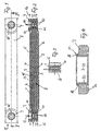
- a transmission oil cooler which consists of several parallel aligned, but held at a distance elongated Plates 1 and 2 made of metal, in particular aluminum is.
- the plates 1 and 2 are each explained in unspecified, because known manner, tightly connected at their peripheral edges and Therefore, each form between them chambers 3 and 4, each of flowed through various media.
- three of the plates 1 and three of the plates 2 are provided, which are outwardly are covered by end plates 5 and 6, of which the plate 5 respectively kinked at their ends and tight, each with a threaded ring 7, which is on its other side close to the first of the Plates 1 is connected.
- the plate 6 in turn closes the heat exchange body 8 of the transmission oil cooler down.
- Coolant is in the embodiment in each case by the open Front ends of the chambers 4 in the direction of arrows 15 occur and it can leave these chambers in the direction of the arrows 16 again. It exists by the arrangement of the shims 11 a seal between Oil and coolant.
- Fig. 4 shows that each of the threaded rings 7 with the top of the Slices 1 is connected and facing away from its surface 7a Side has a concentric collar 18, at the foot of a small circumferential groove 19 is provided.
- the collar 18 also forms a circumferential, from the axis 20 of the threaded ring 7 to the outside obliquely sloping annular surface 21, whose importance will be discussed later becomes.
- the threaded ring 7 has a thread 22.
- FIG. 5 shows, a hollow screw 23 is inserted into this threaded ring, with its flange 24, an opening 25 in a side wall 26 of a not shown water tank of an engine radiator covered.
- a sealing ring 27 is inserted, the of the flange 24 of the hollow screw 23 against the outer surface of the cover plate 5 and pressed against the annular surface 21 of the threaded ring 7 is.
- the sealing ring 27 can therefore easily in a seal relative to the flowed through by cooling water chambers 4 of the Heat exchange body 8 of the transmission oil cooler and a seal to reaches the interior 28 of the water tank not shown in detail become.
- Fig. 5 also shows well that the sealing discs 11th each seal the adjoining chambers 3 and 4 against each other, so that the aforementioned alternate flow through the Chambers 3 and 4 of oil and coolant is achieved.
- Fig. 5 also shows that the hollow screw 23 as a Einsteckstutzen is designed for a plug-in pin 29 of a quick coupling, which in turn with sealing rings on the plug pin 29 for tight connection is provided with the hollow screw 23.
- the sealing ring 27 is in the embodiment of Figs. 6 and 7 a Double sealing ring 270 is provided, the two concentric with each other Torus body 30 and 31 has an elastic material, which are interconnected by a flat ring 32 which with Through openings 33 in the form of uniform on the circumference distributed oblong holes is provided.
- This double sealing ring 270 will open a circumferential shape 34 held by the outer panel. 5 the transmission oil cooler in the region of the opening 25 in the wall 26 is formed becomes.
- the double ring 270 may therefore during assembly of the transmission oil cooling in a very simple way from the outside inserted and centered Be sure and then when the hollow screw 23 is tightened being held.
- circumferential bores 35 provided in the area in which the connecting ring 32 is provided.
- the chambers 3 are each with turbulence inserts 13 provided.
- the chambers 4 are with similar or equal turbulence inserts 13 'equipped.
Landscapes
- Engineering & Computer Science (AREA)
- General Engineering & Computer Science (AREA)
- Mechanical Engineering (AREA)
- Physics & Mathematics (AREA)
- Thermal Sciences (AREA)
- Heat-Exchange Devices With Radiators And Conduit Assemblies (AREA)
- Lubrication Of Internal Combustion Engines (AREA)
- Lubricants (AREA)
- Gears, Cams (AREA)
- Gasket Seals (AREA)
Description
- Fig. 1
- Die Seitenansicht eines erfindungsgemäß ausgestalteten Getriebeölkühlers,
- Fig. 2
- den Schnitt durch den Getriebeölkühler der Fig. 1 längs der Linie II-II,
- Fig. 3
- die Stirnansicht des Getriebeölkühlers der Fig. 1 in Richtung des Pfeiles III der Fig. 1 gesehen,
- Fig. 4
- eine vergrößerte Darstellung des für die Herstellung des Getriebeölkühlers nach den Fig. 1 und 2 verwendeten Gewinderinges,
- Fig. 5
- eine vergrößerte Teildarstellung des linken Endes des Getriebeölkühlers der Fig. 2, jedoch im eingebauten Zustand innerhalb eines Wasserkastens eines Motorkühlers,
- Fig. 6
- eine Darstellung des Anschlußbereiches ähnlich Fig. 5, jedoch bei einer Variante einer Ausführungsform nach der Erfindung und
- Fig. 7
- die Draufsicht auf die bei der Ausführungsform der Fig. 6 verwendete Doppelringdichtung, wobei der in Fig. 6 gezeigte darüberliegende Flanschteil einer Hohlschraube weggelassen ist,
Claims (6)
- Getriebeölkühler mit einem länglichen Wärmetauschkörper (8), der zum Einbau in den Innenraum (28) eines Wasserkastens eines Motorkühlers mit seitlich abragenden Anschlussstutzen versehen ist, die mit je einer Schraubflanschanordnung abgedichtet in einer Öffnung (25) einer Seitenwand (26) des Wasserkastens befestigbar sind,
dadurch gekennzeichnet, dass
der Wärmetauschkörper (8) aus mehreren, parallel zueinander ausgerichteten und auf Abstand gehaltenen Platten (1, 2) aufgebaut und nach außen von Endplatten (5, 6) abgedeckt ist, dass eine der Endplatten (5) im Bereich der Öffnung (25) mit ihrer Außenfläche mit der Innenfläche der Seitenwand (26) fluchtet und an ihrer Innenfläche mit einem Gewindering (7) verbunden ist und dass die Schraubflanschanordnung aus dem Gewindering (7) und einer mit diesem verschraubbaren Hohlschraube (23) besteht, die durch die Seitenwand (26) des Wasserkastens ragt und außen mit ihrem einen Flansch (24) bildenden Kopf gegen einen in die Öffnung (25) der Seitenwand (26) eingesetzten Dichtungsring (27; 270) drückt, der sich an der Außenfläche der Endplatte (5) und am Gewindering (7) anlegt. - Getriebeölkühler nach Anspruch 1, dadurch gekennzeichnet, daß der Dichtungsring (27, 270) an einer Ringfläche (21) des Gewinderinges (7) anliegt.
- Getriebeölkühler nach Anspruch 1, dadurch gekennzeichnet, daß der Dichtungsring (27) auf einem Ansatz (23a) der Hohlschraube (23) aufgeschoben ist und in die Durchführöffnung (25) der Seitenwand (26) hereinragt.
- Getriebeölkühler nach Anspruch 1, dadurch gekennzeichnet, daß der Gewindering (7) unter Zwischenfügung einer Dichtung an der Wand (1) zwischen einer öldurchströmten Kammer (3) und der äußersten vom Kühlmittel durchströmten Kammer (4) des Wärmetauschkörpers (8) angebracht ist.
- Getriebeölkühler nach Anspruch 1, dadurch gekennzeichnet, daß der Gewindering (7) eine umlaufende Nut (19) zum Einsetzen der Endplatte (5) des Wärmetauschkörpers (8) aufweist.
- Getriebeölkühler nach Anspruch 5, dadurch gekennzeichnet, daß die Nut (19) am Fuß eines Dichtkragens (18) des Gewinderinges (7) angeordnet ist, der an seiner Stirnseite eine schräge Ringfläche (21) zur Anlage des Dichtringes (27, 270) bildet.
Priority Applications (1)
| Application Number | Priority Date | Filing Date | Title |
|---|---|---|---|
| EP02026626A EP1288606B1 (de) | 1997-03-18 | 1998-03-18 | Getriebeölkühler |
Applications Claiming Priority (2)
| Application Number | Priority Date | Filing Date | Title |
|---|---|---|---|
| DE19711259 | 1997-03-18 | ||
| DE19711259A DE19711259A1 (de) | 1997-03-18 | 1997-03-18 | Getriebeölkühler |
Related Child Applications (1)
| Application Number | Title | Priority Date | Filing Date |
|---|---|---|---|
| EP02026626A Division EP1288606B1 (de) | 1997-03-18 | 1998-03-18 | Getriebeölkühler |
Publications (3)
| Publication Number | Publication Date |
|---|---|
| EP0866300A2 EP0866300A2 (de) | 1998-09-23 |
| EP0866300A3 EP0866300A3 (de) | 1999-04-28 |
| EP0866300B1 true EP0866300B1 (de) | 2003-02-19 |
Family
ID=7823780
Family Applications (2)
| Application Number | Title | Priority Date | Filing Date |
|---|---|---|---|
| EP98104854A Expired - Lifetime EP0866300B1 (de) | 1997-03-18 | 1998-03-18 | Getriebeölkühler |
| EP02026626A Expired - Lifetime EP1288606B1 (de) | 1997-03-18 | 1998-03-18 | Getriebeölkühler |
Family Applications After (1)
| Application Number | Title | Priority Date | Filing Date |
|---|---|---|---|
| EP02026626A Expired - Lifetime EP1288606B1 (de) | 1997-03-18 | 1998-03-18 | Getriebeölkühler |
Country Status (3)
| Country | Link |
|---|---|
| EP (2) | EP0866300B1 (de) |
| DE (3) | DE19711259A1 (de) |
| ES (2) | ES2192712T3 (de) |
Cited By (2)
| Publication number | Priority date | Publication date | Assignee | Title |
|---|---|---|---|---|
| US7500514B2 (en) | 2003-10-16 | 2009-03-10 | Behr Gmbh & Co. Kg | Coolant radiator for a motor vehicle |
| CN100535400C (zh) * | 2007-06-21 | 2009-09-02 | 上海交通大学 | 紧凑式机油冷却器 |
Families Citing this family (18)
| Publication number | Priority date | Publication date | Assignee | Title |
|---|---|---|---|---|
| JPH11243050A (ja) | 1998-02-24 | 1999-09-07 | Canon Inc | 露光装置 |
| DE19951429B4 (de) * | 1999-10-26 | 2005-02-24 | Behr Gmbh & Co. Kg | Rohranschluß für einen Ölkühler |
| KR20020001186A (ko) * | 2000-06-27 | 2002-01-09 | 배길훈 | 자동차용 트랜스미션 오일쿨러 |
| DE10106510B4 (de) * | 2001-02-13 | 2009-12-10 | Behr Gmbh & Co. Kg | Aluminium-Wärmeübertrager |
| DE10132120A1 (de) | 2001-07-03 | 2003-01-16 | Deere & Co | Ölkühler |
| DE10301564A1 (de) | 2003-01-16 | 2004-08-12 | Behr Gmbh & Co. Kg | Kühlkreislauf einer Brennkraftmaschine mit Niedertemperaturkühler |
| DE102004037392A1 (de) * | 2004-07-30 | 2006-03-23 | Behr Gmbh & Co. Kg | Verfahren zum Löten eines Wärmeübertragers und Wärmeübertrager, hergestellt nach dem Verfahren |
| JP2006057930A (ja) * | 2004-08-20 | 2006-03-02 | Denso Corp | 車両用ラジエータ |
| DE102004051207A1 (de) | 2004-10-20 | 2006-05-04 | Behr Gmbh & Co. Kg | Anordnung zur gegenseitigen Befestigung von Wärmeübertragern, insbesondere in einem Kraftfahrzeug |
| US7188664B2 (en) | 2005-04-21 | 2007-03-13 | Delphi Technologies, Inc. | Aluminum radiator tank with oil cooler clinch fitting |
| FR2886390B1 (fr) * | 2005-05-24 | 2007-08-24 | Valeo Systemes Thermiques | Echangeur de chaleur comportant un faisceau d'echange de chaleur loge dans un boitier |
| FR2886391B1 (fr) * | 2005-05-24 | 2014-01-03 | Valeo Systemes Thermiques | Echangeur de chaleur comportant un faisceau d'echange de chaleur loge dans un boitier |
| EP1739380B1 (de) * | 2005-06-21 | 2012-03-21 | Calsonic Kansei Corporation | Ölkühler |
| JP4722577B2 (ja) * | 2005-06-21 | 2011-07-13 | カルソニックカンセイ株式会社 | オイルクーラ |
| SE532489C2 (sv) | 2007-02-26 | 2010-02-02 | Alfa Laval Corp Ab | Plattvärmeväxlare |
| CN103742464A (zh) * | 2013-12-20 | 2014-04-23 | 广西南宁百兰斯科技开发有限公司 | 一种带有散热翅片的油箱 |
| DE102015015448A1 (de) * | 2015-12-02 | 2017-06-08 | Mann + Hummel Gmbh | Kühlmittelanschluss eines in einem Gehäuse angeordneten Wärmetauschers, Anschlussstutzen, Gehäuseteil und Saugrohr |
| CN106089353A (zh) * | 2016-08-03 | 2016-11-09 | 江门气派摩托车有限公司 | 一种摩托车发动机右曲轴箱体的机油冷却机构 |
Family Cites Families (13)
| Publication number | Priority date | Publication date | Assignee | Title |
|---|---|---|---|---|
| US2898896A (en) * | 1955-11-21 | 1959-08-11 | Gen Motors Corp | Heat exchanger means |
| FR2306421A1 (fr) * | 1975-04-02 | 1976-10-29 | Ferodo Sa | Perfectionnements aux appareils de refroidissement de liquides |
| FR2549593B1 (fr) * | 1983-07-22 | 1987-04-10 | Chausson Usines Sa | Boite a eau d'echangeur de chaleur contenant un echangeur de chaleur secondaire |
| US4538679A (en) * | 1984-11-19 | 1985-09-03 | John T. Hoskins | Fluid coupling assembly |
| FR2579309B1 (fr) | 1985-03-21 | 1989-04-07 | Valeo | Boite a eau d'un echangeur de chaleur pour vehicule automobile, contenant un radiateur d'huile |
| DE3517488A1 (de) * | 1985-05-15 | 1986-11-20 | Süddeutsche Kühlerfabrik Julius Fr. Behr GmbH & Co KG, 7000 Stuttgart | Rohranschluss, insbesondere fuer einen wasserkasten eines waermetauschers einer kraftfahrzeugheizung |
| DE3824073C2 (de) * | 1988-07-15 | 1993-12-09 | Laengerer & Reich Kuehler | Ölkühler |
| DE4029408C2 (de) * | 1990-09-17 | 2003-01-02 | Deutz Ag | Schmierölwärmetauscher einer Brennkraftmaschine |
| DE4035523C1 (en) * | 1990-11-08 | 1992-01-30 | Bayerische Motoren Werke Ag, 8000 Muenchen, De | IC engine oil cooler - is held in position by screw with collar arrangement |
| JP2927009B2 (ja) * | 1991-02-28 | 1999-07-28 | 株式会社デンソー | 二重管式熱交換装置 |
| DE4336952B4 (de) * | 1992-10-29 | 2005-11-24 | Deutz Ag | Motorölkühler für eine Hubkolbenbrennkraftmaschine |
| DE19652639C2 (de) * | 1996-12-18 | 2001-08-02 | Behr Gmbh & Co | Wärmeübertrager für flüssige Medien |
| DE19652782A1 (de) * | 1996-12-19 | 1998-06-25 | Valeo Gmbh | Dichtung für Ölkühler in einem Wasserkasten |
-
1997
- 1997-03-18 DE DE19711259A patent/DE19711259A1/de not_active Withdrawn
-
1998
- 1998-03-18 ES ES98104854T patent/ES2192712T3/es not_active Expired - Lifetime
- 1998-03-18 ES ES02026626T patent/ES2274940T3/es not_active Expired - Lifetime
- 1998-03-18 DE DE59813823T patent/DE59813823D1/de not_active Expired - Lifetime
- 1998-03-18 EP EP98104854A patent/EP0866300B1/de not_active Expired - Lifetime
- 1998-03-18 DE DE59807221T patent/DE59807221D1/de not_active Expired - Lifetime
- 1998-03-18 EP EP02026626A patent/EP1288606B1/de not_active Expired - Lifetime
Cited By (2)
| Publication number | Priority date | Publication date | Assignee | Title |
|---|---|---|---|---|
| US7500514B2 (en) | 2003-10-16 | 2009-03-10 | Behr Gmbh & Co. Kg | Coolant radiator for a motor vehicle |
| CN100535400C (zh) * | 2007-06-21 | 2009-09-02 | 上海交通大学 | 紧凑式机油冷却器 |
Also Published As
| Publication number | Publication date |
|---|---|
| EP0866300A3 (de) | 1999-04-28 |
| ES2192712T3 (es) | 2003-10-16 |
| EP1288606A2 (de) | 2003-03-05 |
| EP0866300A2 (de) | 1998-09-23 |
| DE19711259A1 (de) | 1998-10-15 |
| DE59813823D1 (de) | 2007-01-04 |
| ES2274940T3 (es) | 2007-06-01 |
| DE59807221D1 (de) | 2003-03-27 |
| EP1288606B1 (de) | 2006-11-22 |
| EP1288606A3 (de) | 2003-04-02 |
Similar Documents
| Publication | Publication Date | Title |
|---|---|---|
| EP1288606B1 (de) | Getriebeölkühler | |
| EP0748646A2 (de) | Flüssigkeitsfilter | |
| EP0653043A1 (de) | Wärmetauscher | |
| DE69519636T2 (de) | Kugelventil mit voller öffnung und verfahren zu seiner herstellung | |
| DE19805439B4 (de) | Verfahren zur Herstellung eines Stapelscheibenwärmeübertragers und dadurch hergestellter Wärmeübertrager | |
| DE29610290U1 (de) | Flüssigkeitsfilter | |
| DE19626639C1 (de) | Wärmetauscher, insbesondere Wasserkühler | |
| DE1912905C3 (de) | Korrosionsbeständiger Kegelhahn | |
| DE3824073C2 (de) | Ölkühler | |
| DE60205641T2 (de) | Zur verbindung zweier röhrenförmiger elemente verwendete kupplung und montageverfahren dafür | |
| EP0198109A2 (de) | Absperrschieber | |
| DE3114609C2 (de) | Entlüftungsvorrichtung | |
| DE2335915C3 (de) | Einrichtung zur Halterung und Verbindung von in Reihe geschalteten Vorrichtungen zum Steuern und/oder Konditionieren für Fluide | |
| EP0775513B1 (de) | Flüssigkeitsfilter mit einem Stapelscheiben-Wärmetauscher | |
| DE69523828T2 (de) | Wärmetauscher mit einem Wasserkasten, der einen Ölkühler enthält | |
| DE4411050A1 (de) | Kugelhahn | |
| DE19605340C2 (de) | Wärmeübertrager und Verfahren zu seiner Herstellung | |
| EP0559066A1 (de) | Gehäuse für wärmeisolierte Armaturen und/oder Flanschverbindungen | |
| DE29915384U1 (de) | Kombination aus einer Haupteinheit und wenigstens einer Anbau-Funktionseinheit | |
| EP1348899B1 (de) | Coaxialventil | |
| DE10357419B3 (de) | Innengekühlte Stütz- oder Transportrolle | |
| DE4007880A1 (de) | Ventilpistole fuer ein hochdruckreinigungsgeraet o. dgl. | |
| DE60104339T2 (de) | Rohrkupplung | |
| DE3724567A1 (de) | Waermetauscher fuer kraftfahrzeuge | |
| DE2952467A1 (de) | Waermetauscher, insbesondere zum kuehlen des schmieroels von verbrennungsmotoren |
Legal Events
| Date | Code | Title | Description |
|---|---|---|---|
| PUAI | Public reference made under article 153(3) epc to a published international application that has entered the european phase |
Free format text: ORIGINAL CODE: 0009012 |
|
| AK | Designated contracting states |
Kind code of ref document: A2 Designated state(s): AT BE CH DE LI |
|
| AX | Request for extension of the european patent |
Free format text: AL;LT;LV;MK;RO;SI |
|
| PUAL | Search report despatched |
Free format text: ORIGINAL CODE: 0009013 |
|
| AK | Designated contracting states |
Kind code of ref document: A3 Designated state(s): AT BE CH DE DK ES FI FR GB GR IE IT LI LU MC NL PT SE |
|
| AX | Request for extension of the european patent |
Free format text: AL;LT;LV;MK;RO;SI |
|
| 17P | Request for examination filed |
Effective date: 19990527 |
|
| AKX | Designation fees paid |
Free format text: AT BE CH DE LI |
|
| RBV | Designated contracting states (corrected) |
Designated state(s): DE ES FR GB |
|
| 17Q | First examination report despatched |
Effective date: 20010528 |
|
| GRAH | Despatch of communication of intention to grant a patent |
Free format text: ORIGINAL CODE: EPIDOS IGRA |
|
| GRAH | Despatch of communication of intention to grant a patent |
Free format text: ORIGINAL CODE: EPIDOS IGRA |
|
| GRAA | (expected) grant |
Free format text: ORIGINAL CODE: 0009210 |
|
| AK | Designated contracting states |
Designated state(s): DE ES FR GB |
|
| REG | Reference to a national code |
Ref country code: GB Ref legal event code: FG4D Free format text: NOT ENGLISH |
|
| REF | Corresponds to: |
Ref document number: 59807221 Country of ref document: DE Date of ref document: 20030327 Kind code of ref document: P |
|
| GBT | Gb: translation of ep patent filed (gb section 77(6)(a)/1977) |
Effective date: 20030508 |
|
| REG | Reference to a national code |
Ref country code: ES Ref legal event code: FG2A Ref document number: 2192712 Country of ref document: ES Kind code of ref document: T3 |
|
| ET | Fr: translation filed | ||
| PLBE | No opposition filed within time limit |
Free format text: ORIGINAL CODE: 0009261 |
|
| STAA | Information on the status of an ep patent application or granted ep patent |
Free format text: STATUS: NO OPPOSITION FILED WITHIN TIME LIMIT |
|
| 26N | No opposition filed |
Effective date: 20031120 |
|
| PGFP | Annual fee paid to national office [announced via postgrant information from national office to epo] |
Ref country code: ES Payment date: 20080328 Year of fee payment: 11 |
|
| PGFP | Annual fee paid to national office [announced via postgrant information from national office to epo] |
Ref country code: GB Payment date: 20080326 Year of fee payment: 11 |
|
| GBPC | Gb: european patent ceased through non-payment of renewal fee |
Effective date: 20090318 |
|
| PG25 | Lapsed in a contracting state [announced via postgrant information from national office to epo] |
Ref country code: GB Free format text: LAPSE BECAUSE OF NON-PAYMENT OF DUE FEES Effective date: 20090318 |
|
| REG | Reference to a national code |
Ref country code: ES Ref legal event code: FD2A Effective date: 20090320 |
|
| PGFP | Annual fee paid to national office [announced via postgrant information from national office to epo] |
Ref country code: FR Payment date: 20100408 Year of fee payment: 13 |
|
| PG25 | Lapsed in a contracting state [announced via postgrant information from national office to epo] |
Ref country code: ES Free format text: LAPSE BECAUSE OF NON-PAYMENT OF DUE FEES Effective date: 20090320 |
|
| REG | Reference to a national code |
Ref country code: FR Ref legal event code: ST Effective date: 20111130 |
|
| PG25 | Lapsed in a contracting state [announced via postgrant information from national office to epo] |
Ref country code: FR Free format text: LAPSE BECAUSE OF NON-PAYMENT OF DUE FEES Effective date: 20110331 |
|
| PGFP | Annual fee paid to national office [announced via postgrant information from national office to epo] |
Ref country code: DE Payment date: 20120411 Year of fee payment: 15 |
|
| REG | Reference to a national code |
Ref country code: DE Ref legal event code: R119 Ref document number: 59807221 Country of ref document: DE Effective date: 20131001 |
|
| PG25 | Lapsed in a contracting state [announced via postgrant information from national office to epo] |
Ref country code: DE Free format text: LAPSE BECAUSE OF NON-PAYMENT OF DUE FEES Effective date: 20131001 |