EP0864986B1 - Dispositif, procédé et système de communication de données et programme pour traitement de communication de données dans un support de mémoire - Google Patents
Dispositif, procédé et système de communication de données et programme pour traitement de communication de données dans un support de mémoire Download PDFInfo
- Publication number
- EP0864986B1 EP0864986B1 EP98301792A EP98301792A EP0864986B1 EP 0864986 B1 EP0864986 B1 EP 0864986B1 EP 98301792 A EP98301792 A EP 98301792A EP 98301792 A EP98301792 A EP 98301792A EP 0864986 B1 EP0864986 B1 EP 0864986B1
- Authority
- EP
- European Patent Office
- Prior art keywords
- printer
- interface
- communication
- communication means
- digital camera
- Prior art date
- Legal status (The legal status is an assumption and is not a legal conclusion. Google has not performed a legal analysis and makes no representation as to the accuracy of the status listed.)
- Expired - Lifetime
Links
- 230000006854 communication Effects 0.000 title claims description 380
- 238000004891 communication Methods 0.000 title claims description 378
- 238000000034 method Methods 0.000 title claims description 63
- 238000006243 chemical reaction Methods 0.000 claims description 4
- 230000006870 function Effects 0.000 description 108
- 238000012546 transfer Methods 0.000 description 51
- 238000012545 processing Methods 0.000 description 30
- 238000007639 printing Methods 0.000 description 19
- 230000008859 change Effects 0.000 description 14
- 230000008569 process Effects 0.000 description 13
- 230000005540 biological transmission Effects 0.000 description 9
- 230000006835 compression Effects 0.000 description 9
- 238000007906 compression Methods 0.000 description 9
- 238000001514 detection method Methods 0.000 description 6
- 150000001875 compounds Chemical class 0.000 description 5
- 238000010586 diagram Methods 0.000 description 5
- 230000004044 response Effects 0.000 description 5
- 230000008901 benefit Effects 0.000 description 3
- 238000012217 deletion Methods 0.000 description 3
- 230000037430 deletion Effects 0.000 description 3
- 239000000470 constituent Substances 0.000 description 2
- 238000012937 correction Methods 0.000 description 2
- 230000004913 activation Effects 0.000 description 1
- 238000010017 direct printing Methods 0.000 description 1
- 238000005516 engineering process Methods 0.000 description 1
- 239000004973 liquid crystal related substance Substances 0.000 description 1
- 230000007246 mechanism Effects 0.000 description 1
- 230000003287 optical effect Effects 0.000 description 1
- 230000009466 transformation Effects 0.000 description 1
Images


Classifications
-
- H—ELECTRICITY
- H04—ELECTRIC COMMUNICATION TECHNIQUE
- H04N—PICTORIAL COMMUNICATION, e.g. TELEVISION
- H04N1/00—Scanning, transmission or reproduction of documents or the like, e.g. facsimile transmission; Details thereof
- H04N1/00127—Connection or combination of a still picture apparatus with another apparatus, e.g. for storage, processing or transmission of still picture signals or of information associated with a still picture
- H04N1/00278—Connection or combination of a still picture apparatus with another apparatus, e.g. for storage, processing or transmission of still picture signals or of information associated with a still picture with a printing apparatus, e.g. a laser beam printer
-
- G—PHYSICS
- G06—COMPUTING; CALCULATING OR COUNTING
- G06F—ELECTRIC DIGITAL DATA PROCESSING
- G06F13/00—Interconnection of, or transfer of information or other signals between, memories, input/output devices or central processing units
- G06F13/38—Information transfer, e.g. on bus
- G06F13/40—Bus structure
- G06F13/4004—Coupling between buses
- G06F13/4027—Coupling between buses using bus bridges
-
- H—ELECTRICITY
- H04—ELECTRIC COMMUNICATION TECHNIQUE
- H04N—PICTORIAL COMMUNICATION, e.g. TELEVISION
- H04N1/00—Scanning, transmission or reproduction of documents or the like, e.g. facsimile transmission; Details thereof
- H04N1/00127—Connection or combination of a still picture apparatus with another apparatus, e.g. for storage, processing or transmission of still picture signals or of information associated with a still picture
- H04N1/00204—Connection or combination of a still picture apparatus with another apparatus, e.g. for storage, processing or transmission of still picture signals or of information associated with a still picture with a digital computer or a digital computer system, e.g. an internet server
- H04N1/00236—Connection or combination of a still picture apparatus with another apparatus, e.g. for storage, processing or transmission of still picture signals or of information associated with a still picture with a digital computer or a digital computer system, e.g. an internet server using an image reading or reproducing device, e.g. a facsimile reader or printer, as a local input to or local output from a computer
- H04N1/00241—Connection or combination of a still picture apparatus with another apparatus, e.g. for storage, processing or transmission of still picture signals or of information associated with a still picture with a digital computer or a digital computer system, e.g. an internet server using an image reading or reproducing device, e.g. a facsimile reader or printer, as a local input to or local output from a computer using an image reading device as a local input to a computer
-
- H—ELECTRICITY
- H04—ELECTRIC COMMUNICATION TECHNIQUE
- H04N—PICTORIAL COMMUNICATION, e.g. TELEVISION
- H04N2201/00—Indexing scheme relating to scanning, transmission or reproduction of documents or the like, and to details thereof
- H04N2201/0008—Connection or combination of a still picture apparatus with another apparatus
- H04N2201/0015—Control of image communication with the connected apparatus, e.g. signalling capability
-
- H—ELECTRICITY
- H04—ELECTRIC COMMUNICATION TECHNIQUE
- H04N—PICTORIAL COMMUNICATION, e.g. TELEVISION
- H04N2201/00—Indexing scheme relating to scanning, transmission or reproduction of documents or the like, and to details thereof
- H04N2201/0008—Connection or combination of a still picture apparatus with another apparatus
- H04N2201/0034—Details of the connection, e.g. connector, interface
- H04N2201/0044—Connecting to a plurality of different apparatus; Using a plurality of different connectors
-
- H—ELECTRICITY
- H04—ELECTRIC COMMUNICATION TECHNIQUE
- H04N—PICTORIAL COMMUNICATION, e.g. TELEVISION
- H04N2201/00—Indexing scheme relating to scanning, transmission or reproduction of documents or the like, and to details thereof
- H04N2201/0008—Connection or combination of a still picture apparatus with another apparatus
- H04N2201/0034—Details of the connection, e.g. connector, interface
- H04N2201/0048—Type of connection
- H04N2201/0049—By wire, cable or the like
-
- H—ELECTRICITY
- H04—ELECTRIC COMMUNICATION TECHNIQUE
- H04N—PICTORIAL COMMUNICATION, e.g. TELEVISION
- H04N2201/00—Indexing scheme relating to scanning, transmission or reproduction of documents or the like, and to details thereof
- H04N2201/0008—Connection or combination of a still picture apparatus with another apparatus
- H04N2201/0034—Details of the connection, e.g. connector, interface
- H04N2201/0048—Type of connection
- H04N2201/0053—Optical, e.g. using an infrared link
-
- H—ELECTRICITY
- H04—ELECTRIC COMMUNICATION TECHNIQUE
- H04N—PICTORIAL COMMUNICATION, e.g. TELEVISION
- H04N2201/00—Indexing scheme relating to scanning, transmission or reproduction of documents or the like, and to details thereof
- H04N2201/0008—Connection or combination of a still picture apparatus with another apparatus
- H04N2201/0034—Details of the connection, e.g. connector, interface
- H04N2201/0048—Type of connection
- H04N2201/0055—By radio
-
- H—ELECTRICITY
- H04—ELECTRIC COMMUNICATION TECHNIQUE
- H04N—PICTORIAL COMMUNICATION, e.g. TELEVISION
- H04N2201/00—Indexing scheme relating to scanning, transmission or reproduction of documents or the like, and to details thereof
- H04N2201/0077—Types of the still picture apparatus
- H04N2201/0081—Image reader
-
- H—ELECTRICITY
- H04—ELECTRIC COMMUNICATION TECHNIQUE
- H04N—PICTORIAL COMMUNICATION, e.g. TELEVISION
- H04N2201/00—Indexing scheme relating to scanning, transmission or reproduction of documents or the like, and to details thereof
- H04N2201/0077—Types of the still picture apparatus
- H04N2201/0084—Digital still camera
Definitions
- the present invention relates to a data communication apparatus, a method and a system therefor, and a program for data communication process stored in a memory medium, and more particularly to a technology for causing plural devices corresponding to communication methods of different formats to be recognized as a single communication system.
- IEEE 1394 standard defines two transfer methods, namely the isochronous transfer mode and the asynchronous transfer mode.
- the isochronous transfer mode ensures the transmission and reception of a predetermined amount of data in each communication cycle (125 ⁇ s) and is executive for the real-time transfer of image signal or voice signal, while the asynchronous transfer mode executes transmission and reception asynchronously with the communication cycle and is executive for transmitting and receiving the control commands and the file data whenever necessary.
- the asynchronous mode has a lower priority in comparison with the isochronous mode.
- the configuration of connection of the communication system can be automatically recognized. More specifically, in response to a change in the configuration of connection, resulting from the addition of a new device, the deletion of a connected device, the on/off operation of power supply of a connected device, there is automatically executed the recognition of the configuration of connection of the newly constructed system and the setting of ID information for the device constituting such system.
- the IEEE 1394 standard is provided with a function of relaying the data transmitted from each device.
- the communication packet, transmitted from each device in the isochronous transfer mode or the asynchronous transfer mode is transferred, by such relaying function, to all the device on the communication system.
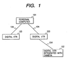
- Fig. 1 illustrates an example of a serial-bus type communication system constituted by plural electronic device equipped with the digital interfaces based on the IEEE 1394 standard (hereinafter written as 1394 interface).
- the electronic device are connected in a tree shape configuration.
- a personal computer 103 a portable digital VTR 102 such as a digital camcorder, a desk-top VTR 103 capable, for example, of dubbing the digital image data of the camcorder 102, and communication cables 104 connecting the 1394 interfaces provided on the electronic device.
- a portable digital VTR 102 such as a digital camcorder
- a desk-top VTR 103 capable, for example, of dubbing the digital image data of the camcorder 102
- communication cables 104 connecting the 1394 interfaces provided on the electronic device.
- a concern of the present invention is to solve the above-described drawbacks.
- Another concern of the present invention is, in a data communication apparatus, to cause a device corresponding to the communication method of a standard different for example from the IEEE 1394 standard on which the communication system is based, to be recognized as a component of such communication system. Also it is to cause a function of the device corresponding to the communication method of a standard different from that of the communication system to be recognized as a function provided in the device constituting such communication system.
- a data communication apparatus as set out in claim 1, a method of transmitting data as set out in claim 11, and a storage medium as set out in claim 17.
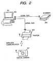
- Fig. 2 is a view showing the configuration of a communication system constituting a first embodiment of the present invention, wherein the communication system includes a printer 202, a personal computer 203 and a scanner 204, and all the device execute communication through communication interfaces based on a communication method of a common standard. Also the digital camera 201 executes communication with the printer 202, through communication interfaces of a standard different from that of the communication system.
- the digital camera 201 is a portable device provided with a communication interface for wireless communication.
- the printer 202 is provided with a communication interface capable of wireless communication with the digital camera 201, and has two functions as a direct printer and as a network printer.
- the direct printer means an operation status capable of communication with the digital camera 201 only, while the network printer means an operation status capable of communication with the digital camera 201 and the communication system.
- the printer 202 is also provided with a communication interface based on the IEEE 1394 standard (hereinafter called 1394 interface).
- the personal computer (hereinafter also written as PC) 203 is provided with a 1394 interface and is connected with the printer 202 through a communication cable based on the IEEE 1394 standard.
- the scanner 204 is provided with a 1394 interface, and is connected with the PC 203 through a communication cable.
- the printer 202, the PC 203 and the scanner 204 constitute a communication system based on the IEEE 1394 standard.
- the PC 203 is capable of recording image data read by the scanner 204, and image processing such as editing or working on such image data.
- the printer 202 is capable, in the function as the direct printer, of printing an image taken by the digital camera 201, and, in the function as the network printer, of printing an image read by the scanner 204 or processed by the PC 203. Also the printer 202 is capable of receiving the image data taken by the digital camera 201 and transferring such image data to the PC 203 through the 1394 interface.
- the 1394 interface provided in each device is constituted by a physical layer, a link layer and a bus management unit. In the following there will be explained the function and the processing operations of the 1394 interface.
- the 1394 interface can accommodate data transfer rates of 100, 200 and 400 Mbps.
- the 1394 interface supporting an upper data transfer rate is so constructed as to also support the lower data transfer rates.
- the 1394 interface also has a function of receiving data transmitting from a device and repeating such data to another device.
- the 1394 interface executes a process called bus resetting, according to an increase or a decrease in the device constituting the communication system and to an on/off operation of the power supply in each device, in the following manner.
- the 1394 interface After an automatic detection of a change in the connection configuration of the communication system, the 1394 interface resets the connection configuration that has been recognized up to this point. Secondly, the 1394 interface determines the mother-daughter relationship of the connected device, and recognizes the new connection configuration as a hierarchic connection relationship. Thirdly, the 1394 interface automatically sets the ID starting from terminal device in the communication system, and transmits the set information of the interface (for example connection relationship with other device, supported data transfer rate, supplied or consumed electric power etc.) to the device present on the communication system. The process explained above is executed by the physical layer equipped in the 1394 interface.
- the physical layer of the 1394 interface constantly monitors the change in the bias voltage applied to the communication port, and detects the change in the connection configuration by a change in such voltage.
- a device that has detected the change in the bias voltage transfers a signal, requesting a bus resetting, to the 1394 interfaces of other device.
- the above-mentioned bus resetting is started after all the device have finally received the signal requesting the bus resetting.
- the above-mentioned bus resetting can also be activated, in addition to the activation by the change in the connection configuration, also by a direct request from a device itself to the physical layer.
- the physical layer in addition has functions of encoding and decoding of the transmitted and received data by the DS-link method, and of mediation (arbitration) of the bus use right.
- the link layer has functions of control of the asynchronous transfer mode and the isochronous transfer mode, generation and detection of a communication packet based on the asynchronous transfer mode and the isochronous transfer mode, generation and detection of an error detection code attached to each communication packet, generation of a cycle start packet for controlling the communication cycle etc.
- the bus management unit executes control of the functions of the physical and link layers, management of the band and the channel number in the isochronous transfer mode, management of the communication between an application and the link layer, and also management on the information relating to the connection configuration of the communication system, the data transfer rate and the power supply of each device.
- the printer 202 is provided with two 1394 interfaces and a wireless interface of a communication method different from the IEEE 1394 standard.
- One of the two 1394 interfaces is connectable with an external device provided with a 1394 interface, and a node ID automatically assigned by the physical layer constituting such 1394 interface indicates the printer 202 itself.
- the other 1394 interface is provided inside the printer 202, and node information assigned by the physical layer thereof indicates an external device (digital camera 201) communicating with the above-mentioned wireless interface.
- the wireless interface of the printer 202 supports an infrared communication method based on the IrDA standard.
- the node ID mentioned above is ID information for identifying each device (node) constituting the communication system based on the IEEE 1394 standard.
- the node ID consists of a node number and bus number and is automatically set according to a change in the connection configuration of the communication system.
- the printer 202 receives, through the wireless interface, image data transmitted from the digital camera 201 based on a data communication method based on the IrDA standard.
- the printer 202 is so constructed as to transfer the received image data to the 1394 interface and to output such image data to the communication system based on the IEEE 1394 standard. Therefore, the digital camera 201, even executing communication based on a communication method different from that of the PC 203 or the scanner 204, can transfer the image data to these devices. Consequently all the device constituting the communication system of the first embodiment need not be equipped with the wireless interfaces communicable with the digital camera 201. Also in the first embodiment, the digital camera 201 and the printer 202 execute wireless communication. Consequently the digital camera 201 does not lose the mobility of the portable device and can transfer the image data to the various device without cumbersome cable connection.
- the data communication between the printer 202 and the digital camera 201 is achieved by infrared communication based on the IrDA standard, but such communication method is not restrictive. There may be adopted any communication method, as long as the features of the portable device, such as mobility or compactness are not lost. Also in the first embodiment the portable device executing wireless communication with the printer 202 is constituted by the digital camera 201, but there may be employed another portable device such as a camcorder.
- the configuration shown in Fig. 2 is a mere example, and there may be employed a configuration in which plural device provided with the 1394 interfaces are directly or indirectly connected to the PC 203 or the scanner 204.
- the communication system is constituted by the printer 202, the PC 203 and the scanner 204, but there may also be adopted any device capable of constituting a communication system based on the IEEE 1394 standard, for example an external memory such as a hard disk, or a digital device such as a CD player or a DVD player.
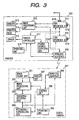
- Fig. 3 is a block diagram showing the configuration of the digital camera 201 and the printer 202 shown in Fig. 2.
- an image pickup unit 301 In the digital camera 201 shown in Fig. 3, there are shown an image pickup unit 301; an image processing unit 302 for converting the image outputted from the image pickup unit 301 into image data of a predetermined format; and an encoding/decoding unit 303 for applying predetermined high-efficiency encoding (for example variable encoding after DCT transformation and digitizing) on the image data outputted from the image processing unit 302.
- the encoding/decoding unit 303 also executes expansion decoding on the compressed image data reproduced from a recording/reproduction unit 304, and sends thus decoded data to the image processing unit 302.
- a recording/reproducing unit 304 for recording or reproducing the compressed encoded image data on or from an unrepresented recording medium; an operation unit 305 for instructing processes in the digital camera 201; a control unit 306 provided with a microcomputer and a memory capable of storing predetermined program codes, and controlling and managing the operations of the various units constituting the digital camera 201; a display unit 307 for displaying the image taken by the image pickup unit 301 by means of an EVF (electronic view finder) or a liquid crystal panel; and a wireless interface 308 for executing wireless communication of the image data taken by the image pickup unit 301, based on the data communication method for example based on the IrDA standard.
- the digital camera 201 of the present embodiment executes the compression encoding of the image data, utilizing for example the JPEG (joint photographic experts group) method.
- a wireless interface 309 capable of infrared communication with the digital camera 201 based on the IrDA standard; and a 1394 interface B 310 for converting the output of the wireless interface 309 into a data format based on the IEEE 1394 standard, for output onto the communication system.
- the node ID set by the 1394 interface B indicates the device executing communication with the wireless interface B.
- a 1394 interface A for printer connected with the 1394 interface B connected in the printer 202 and connectable with the PC 203 and the scanner 204.
- the node ID set by the 1394 interface A 311 indicates the printer 202 itself.
- an image processing unit 312 for processing the image data supplied from the 1394 interface A 311, the 1394 interface B 310 or the wireless interface 309 into a printable image
- a memory 313 employed for forming the image data into a printable image
- a printer head 314 a driver 315 for controlling the function of the printer head 314 and a paper feeding mechanism
- an operation unit 316 for controlling the operation mode etc. of the printer 202
- a printer controller 317 provided with a microcomputer and a memory capable of storing predetermined program codes and adapted to control and manage the functions of the various units constituting the printer 202
- a power supply unit 318 for supplying the 1394 interface A 311, the 1394 interface B 310 and the wireless interface 309 with the necessary electric power.
- the printer 202 is provided with two 1394 interfaces A 311, B 310 for allowing to set two different node ID's to be set.
- the 1394 interfaces A 311 and B 310 are mutually connected inside the printer 202 through a communication port 319.
- the 1394 interface B 310 is so constructed as to convert the data received by the wireless interface 309 into data of a communication method based on the IEEE 1394 standard and to send such data to the 1394 interface A 311. Consequently the node ID assigned by the 1394 interface B 310 indicates the device executing communication through the wireless interface 309, namely the digital camera 201.
- the 1394 interface A 311 can be connected with the 1394 interface equipped in an external device and the node ID assigned by the physical layer indicates the printer 202 itself. In this manner two different node ID's can be set by the two 1394 interfaces provided in the printer 202.
- the image taken by the image pickup unit 301 is converted into a data format suitable for display in the image processing unit 302, and is then displayed on the display unit 307. If the user manipulates the operation unit 305 to set the digital camera 201 at the recording state, the image taken by the image pickup unit 301 is supplied through the image processing unit 302 to the encoding/decoding unit 303. The image data supplied thereto are subjected to compression encoding therein and are recorded in the recording medium (not shown) provided in the recording/reproducing unit 304.
- the digital camera 201 reads the desired image from the recording medium provided in the recording/reproducing unit 304.
- the desired image is read by the control of the recording/reproducing unit 304 by the control unit 306 according to the instruction of the user entered through the operation unit 305.
- the encoding/decoding unit 303 executes an expansion decoding process based on the JPEG system, on the image data reproduced from the unrepresented recording medium.
- the image data after expansion decoding are converted into a data format suitable for display in the image processing unit 302 and are displayed on the display unit 307.
- image data In case of transferring the desired image data, reproduced from the recording medium provided in the recording/reproducing unit 304, to the printer 202 or a device (for example the PC 203) on the communication system connected with the printer 202, such image data are supplied to the wireless interface 308.
- the image data, sent by wireless transmission from the digital camera 201, are converted, in the state of JPEG compression encoded data, into a data format based on the IrDA method and are wireless transmitted to the wireless interface 309 of the printer 202.
- the image data received by the wireless interface 309 of the printer 202 are supplied, through the image processing unit 312 of the 1394 interface B 310, to the device on the communication system. In this state, the output data from the wireless interface 309 correspond to the data prior to the entry into the wireless interface 308.
- the printer controller 317 In case of transferring the image data, sent by wireless transmission from the digital camera 201, to the device on the communication system through the printer 202 of the above-described configuration, the printer controller 317 so controls the electric power supplied to the 1394 interfaces A 311, B 310 as to ensure the proper function thereof. In this state, the printer 202 functions as the network printer, thus being capable of communication with any device constituting the communication system.
- the image data transmitted from the digital camera 201 are supplied from the wireless interface 309 to the 1394 interface B 310, and are converted into a packet of a communication method based on the IEEE 1394 standard, for example the isochronous transfer mode.
- the isochronous packet outputted from the 1394 interface B 310 is transferred through the 1394 interface A 311 to all the device on the communication system, including the PC 203. In this state the image data from the 1394 interface B 310 are transferred in the isochronous transfer mode, but can also be transferred to a specified device by the asynchronous transfer mode.
- the printer controller 317 cuts off the power supply to the 1394 interfaces A 311, B 310 thereby disabling the communication function thereof.
- the 1394 interface provided in each device on the communication system identifies that the printer 202 is separated from the communication system and automatically recognizes again the configuration of the communication system excluding the printer 202.
- the printer 202 itself enables the communicating function of the wireless interface 309 only, and executes communication with the device capable of communicating with the wireless interface 309. Consequently the image data transmitted from the digital camera 201 are supplied only to the image processing unit 312 in the printer 202 through the wireless interface 309.
- the 1394 interface provided in each device detects the addition or deletion of a device to or from the communication system by the change of the bias voltage supplied to the communication cable. Therefore, in case of the function as the direct printer, the printer 202 completely cuts off the electric power supply to the 1394 interfaces A 311, B 310, thereby terminating all the functions relating to the communication of the 1394 interface and terminating the bias voltage supply to the communication cable.
- the image processing unit 312 decodes the image data, subjected to the JPEG compression encoding, utilizing a JPEG decoding program file stored in an unrepresented ROM or decoding data transmitted from the digital camera 201 together with the compressed image data. Also the image processing unit 312 converts the decoded image data into a data format, suitable for printing, utilizing the memory 313 and stores the converted data in the memory 313. The image data stored in the memory 313 are supplied to the printer head 216 and printed therein.
- the printing operation is rendered possible by supplying the image processing unit 312 with the data entered from the 1394 interface A 311.
- the printer controller 317 cuts off the electric power supply to the 1394 interface, thereby disabling the communicating function thereof.
- the device constituting the communication system for example the PC 203, can transfer image data or command data to the digital camera 201.
- the data transferred from the PC 203 are supplied through the 1394 interfaces A 311, B 310 of the printer 202 to the wireless interface 309, converted into the data format based on the IrDA standard and are wireless transmitted to the digital camera 201.
- the printer controller 317 controls the various process units of the printer 202, and, in case the printer 202 is operated as the direct printer or the network printer, the user enters the instruction into the operation unit 305 or 316 of the digital camera 201 or the printer 202.
- the printer controller 317 controls the electric power supplied from the power supply unit 318 to the 1394 interfaces B 310, A 311 so as to enable the function of either one.
- the communication system of the first embodiment can recognize the device executing communication by a communication method different from that of the communication system, as a constituting device and can execute the data communication with such device by the communication method same as that of the communication system. Also the communication system of the first embodiment can recognize the digital camera 201 and the printer 202 as separate nodes. Furthermore, the printer 202 of the first embodiment can utilize the printer 202 independently as the network printer or as the direct printer, by controlling the power supply to the two interfaces equipped in the printer 202. In case of function as the direct printer, the printer 202 can execute rapid data communication without being influenced by the communication in the communication system.
- the JPEG compressed image data are transferred from the digital camera 201 to the printer 202 and decoded therein to achieve an improved transfer efficiency in comparison with the case of transfer of the non-compressed image data.
- the decoding process corresponding to the JPEG method can be achieved either by a hardware, namely by a JPEG decoding circuit (board) or by a software.
- the printer 202 itself may be provided therein with a decoder without difficulty in cost and with an advantage of compactization of circuitry.
- Fig. 4 shows the details of the communication interfaces provided in the digital camera 201 and the printer 202.
- the wireless interfaces 308, 309 provided in the digital camera 201 and the printer 202 execute infrared communication based on the IrDA standard.
- the 1394 interfaces A 311, B 310 provided in the printer 202 execute data communication based on the IEEE 1394 standard, with the PC 203 and the scanner 204.
- the 1394 interface B 310 converts the data received by the wireless interface 309 into a communication packet based on the IEEE 1394 standard, so that the digital camera 201 can execute data communication with the device connected to the 1394 interface A 311.
- the wireless interface 308 of the digital camera 201 includes a modulation/demodulation unit 401, a light receiving unit 402 and a light emitting unit 403.
- the wireless interface 309 of the printer 202 includes a light receiving unit 304, a light emitting unit 405 and a modulation/demodulation unit 406.
- each of the 1394 interfaces A 311, B 310 provided in the printer 202 has a function and a configuration based on the IEEE 1394 standard.
- the 1394 interface is provided at least with a physical layer, a link layer and a bus management unit.
- the physical layer has functions of bus initialization, encoding/decoding of transmitted/received data, mediation of bus use right etc.
- the link layer has functions of generation/detection of error correction code, generation/detection of packet, cycle control etc.
- the bus management unit has functions of controlling the link layer and controlling communication with application.
- a port 319 of the 1394 interface B 310 is always connected to a port 319 of the 1394 interface A 311. Also a port 319 thereof is connected with the PC 203 shown in Fig. 1 through the communication cable.
- the printer 202 is given node information of the 1394 interface A 311 for the main body of the printer 202 and another node information of the 1394 interface B 310 for the device connected to the wireless interface 309 (namely the digital camera 201 in the present embodiment). In this manner the PC 203 and the scanner 204 constituting the communication system of the IEEE 1394 standard can recognize the digital camera 201 and the printer 202 as separate device.
- the printer 202 in order to set two node ID's within a single device, the printer 202 is provided therein with two independent 1394 interfaces which are mutually connected inside the printer 202, but it is also possible to construct a backplane environment based on the IEEE 1394 standard by connecting the physical layers of the 1394 interfaces to a backplane bus.
- the electric power to the 1394 interfaces A 311, B 310 is supplied from the power supply unit 318.
- the printer controller 317 controls the electric power supply according to the operation mode of the digital camera 201. For example, in case of printing the image taken by the digital camera 201 by direct communication with the printer 202, the printer controller 317 totally or partly cuts off the electric power supply to the 1394 interfaces A 311, B 310 to disable the function of the physical layers thereof, which therefore become inactive and terminate the supply of the bias voltage to the communication cable. Detecting such change in the bias voltage, the communication system of the IEEE 1394 standard starts the recognition of the new system configuration. Thus the communication system recognizes the digital camera 201 and the system configuration in which the digital camera 201 is separated from the printer 202.
- the function of the wireless interface 309 alone becomes effective in the printer 202. Consequently the printer 202 functions as the direct printer and executes 1 to 1 communication with the digital camera 201 through the wireless interface 309. Also, in case the printer controller 317 disables the functions of the 1394 interfaces A 311, B 310, the electric power supply thereto may be cut off completely. Otherwise the electric power supply to the physical layers of the 1394 interfaces may be partially cut off to terminate only the supply of the bias voltage.
- the printer controller 317 supplies the 1394 interfaces 211, 210 with electric power, thereby realizing the function as the network printer.
- the printer 202 functions as the network printer, thereby printing the data from the device constituting the communication system, including the digital camera 201.
- the printer controller 317 can change the printer 202 to a network configuration matching the purpose of the user, by controlling the electric power supply to the interfaces 310, 311 according to the operation mode of the digital camera 201. Also by providing the 1394 interface A 311 as the communication interface for the printer 202 and the 1394 interface B 310 and the wireless interface 309 as the communication interfaces for the digital camera 201, as in the present embodiment, even a device not provided with the 1394 interface such as the digital camera 201 can be recognized as a node if it is capable of communication with the printer 202. Also in the present embodiment, the wireless interface 309 is constantly powered by the power supply unit 220.
- Fig. 5 shows the structure of the communication packet communicated between the communication interfaces of the present embodiment.
- (a) indicates the structure of a communication packet based on the IrDA standard.
- the communication packet of the IrDA standard is wireless communicated by a unit, called "frame", consisting of information data of a predetermined amount.
- BOF beginning of frame
- EOF end of frame
- Each frame includes a FCS (frame check sequence) field 505 containing error correction data, an address field 502 containing address data, a control field 503 containing control data, and an information field 504 containing information data.
- the information field 504 contains the image data subjected to JPEG compression encoding, and control data relating to such compression encoding.
- the data indicating the operation mode of the digital camera 201 in the present embodiment are also contained in the information field 504.
- the communication packet shown in Fig. 5 is generated by the modulation/demodulation unit 301 of the wireless interface 308, and is wireless transmitted through the light emitting unit 303.
- the light receiving unit 304 of the printer 202 receiving the communication packet of the above-described structure, sends such packet to the modulation/demodulation unit 406, which judges the content of the data contained in the information field 504 from the data contained in the control field 503. If the data contained in the information field 504 are data indicating the operation mode of the digital camera 201, the printer controller 317 controls the function of the printer 202 according to the content of such data. Also if the data contained in the information field 504 are JPEG encoded image data, such data are demodulated in the modulation/demodulation unit 406 and supplied to the 1394 interface B 310 or the image processing unit 312.
- the image data supplied to the 1394 interface B 310 are converted into a communication packet of the isochronous transfer mode based on the IEEE 1394 standard.
- (b) indicates the structure of the communication packet of the isochronous transfer mode, which is composed of a header portion 508, a header portion CRC 509, a data portion 510 and a data portion CRC 511.
- the JPEG compressed image data contained in the information field 504 of the communication packet based on the IrDA standard, are contained in the data portion 510 of the communication packet based on the IEEE 1394 standard.
- the communication packet based on the IEEE 1394 standard is transferred, through the port 319 of the 1394 interface B 310, to the desired device on the communication system.
- the communication packet transferred from the PC 203 is supplied, through the 1394 interface A 311 and 1394 interface B 310, to the wireless interface 309, which converts the data of the data portion 510, supplied from the 1394 interface B 310, into a communication packet of the IrDA standard contained in the information field 504.
- the communication packet of the IrDA standard is converted into a signal for infrared communication by the modulation/demodulation unit 406 and is wireless transmitted to the digital camera 201 from the light emitting unit 405.
- the light receiving unit 402 of the wireless interface 308 of the digital camera 201 receives the transmitted communication packet, which is demodulated by the modulation/demodulation unit 401 and the data contained in the packet is supplied to the recording/reproducing unit 304 or the system controller 306.
- FIG. 6, 7 and 8 for explaining the method for switching the function of the printer 202 of the first embodiment according to the operation mode of the digital camera 201.
- Fig. 6 shows a switch 601 for switching plural operation modes of the digital camera 201, constituting a part of the operation unit 305 equipped in the digital camera 201.
- Fig. 7 is a table showing the operation states of the plural communication interfaces (enabled or disabled state of each communication interface) provided in the printer 202, corresponding to the respective operation mode of the digital camera 201, and
- Fig. 8 is a flow chart showing the functions of the communication system of the first embodiment.
- OFF indicates a state in which the power supply of the main body of the digital camera 201 is turned off;
- photographing indicates a state in which the image pickup unit 301 of the digital camera 201 is enabled to take the image of an object; and
- production indicates a state of reproducing the image data from the unrepresented recording medium according to the instruction of the user.
- these three states are called "normal operation modes". In these modes, the digital camera 201 does not execute communication with the external device.
- the digital camera 201 sends control data indicating the "normal operation modes” to the printer 202 (step S801).
- the printer 202 terminates the communication with the digital camera 201, also controls the 1394 interfaces A 311, B 310 and constantly monitors the change in the operation mode of the digital camera 201.
- the printer controller 317 so controls the power supply unit 318 to disable the function of the 1394 interface B 310 of the digital camera 201 and to enable the function of the 1394 interface A 311 (S802). Consequently the printer 202 can communicate with the various device on the communication system, other than the digital camera 201, and can print the output of such various device.
- the wireless interface 309 of the printer 202 is constantly powered in order to receive the control data from the digital camera 201.
- the printer 202 identifies the "normal operation modes" from the control data transmitted from the digital camera 201, but there may also be adopted a configuration allowing direct entry of control data indicating the "normal operation modes” from the operation unit 316 of the printer 202. It is also possible to provide the printer 202 with timer means for measuring the time after the termination of the communication with the digital camera 201 and to automatically identify the "normal operation modes" after the lapse of a predetermined time.
- the device on the communication system executes setting of the topology, excluding the digital camera 201, according to the method based on the IEEE 1394 standard (step S803). Then the printer 202 prints the information data entered through the 1394 interface A 311 (step S804).
- the printer 202 functions as a network printer capable of communication solely with the communication system excluding the digital camera 201.
- direct printer indicates an operation of transmitting the image data, designated in the digital camera 201, directly to the printer 202 and printing such image data therein.
- the printer 202 does not execute communication with the device on the communication system, for example the PC 203 connected to the 1394 interface A 311.
- such operation mode is called “direct printer mode", in which the printer 202 prints solely the output of the digital camera 201.
- the digital camera 201 transmits control data indicating the "direct printer mode” to the printer 202 (step S805).
- the printer 202 for executing data communication with the digital camera 201, controls the power supply unit 318 to disable the function of the 1394 interfaces A 311, B 310 of the printer 202 (step S806). In this manner the printer 202 can communicate solely with the digital camera 201 without being influenced by the communication on the communication system, so that the user can preferentially execute the output from the digital camera 201. Also in the "direct printer mode", the communication system connected to the 1394 interface A 311 automatically recognizes that the digital camera 201 and the printer 202 are both disconnected from the network (step S807). In the present embodiment, the printer 202 is so controlled as to function as the direct printer according to the control data transmitted from the digital camera 201, but the system may also be so constructed as to execute such control according to the input from the operation unit 316.
- the image data outputted from the digital camera 201 are supplied, through the wireless interface 308, to the image processing unit 312 of the printer (step S808) and printed therein (step S809).
- the user controls the operation unit 305 of the digital camera 201 for transmitting such image data (step S810).
- PC fetching in Fig. 6 indicates an operation mode of transferring the image data, designated by the digital camera 201, to the PC 203 of the communication system through the printer 202.
- operation mode is called “network mode”.
- the printer 202 functions as the network printer for printing the information data outputted from the device on the communication system, including the digital camera 201.
- step S811 the digital camera 201 transmits control data indicating such operation mode
- the printer 202 executes electric power supply to the 1394 interfaces A 311, B 310 to cause the communication system to recognize the presence of the digital camera 201 (step S812). More specifically, the printer controller 317 enables both 1394 interfaces A 311, B 310 whereby node information are assigned to the printer 202 and the digital camera 201 (step S813).
- the device on the communication system can recognize not only the printer 202 but also the digital camera 201 as the device on the communication system, whereby the digital camera 201 can execute data communication based on the IEEE 1394 standard.
- the printer 202 is so controlled as to function as the network printer in response to the control data transmitted from the digital camera 201, but the system may also be so constructed as to execute such control according to the input from the operation unit 316.
- the printer 202 converts the compressed image data or the control data, wireless transmitted from the digital camera 201, into the communication packet based on the isochronous transfer mode and transfers the packet to the PC 203 (step S814).
- the PC 203 receives the communication packet transmitted by the isochronous transfer, memorizes the compressed image data contained therein and executes image processing such as editing (step S815). Also in case of transferring other image data to the PC 203, the user manipulates the operation unit 305 of the digital camera 201 to transmit such image data (step S816). In the present embodiment, there may also be adopted a configuration of selecting and designating the image taken by the digital camera 201 by transmitting a control command for the digital camera 201 from the PC 203.
- the 1394 interface B 310 of the present embodiment converts the image data, transmitted from the digital camera 201, into the communication packet of the isochronous transfer mode, but the image data may also be converted into a communication packet of the asynchronous transfer mode by designating the destination of communication in the digital camera 201.
- the PC 203 is selected as the destination of communication of the digital camera 201, but there may be selected any device on the communication system.
- the above-explained configuration allows to control the function of the printer 202 according to the operation mode of the digital camera 201, thereby realizing an optimum network configuration for the digital camera 201 and the printer 202. More specifically, in case the digital camera 201 is in the "normal operation mode” (in the power-off state, in the image pickup state or in the image reproducing state) or in the "network mode", the printer 202 can function as the network printer. Also in case the digital camera 201 is in the "direct printer mode", the printer 202 can function as the direct printer.
- the above-described configuration enables to connect the digital camera 201 without the 1394 interface to the communication system based on the IEEE 1394 standard, and to cause each device constituting such communication system to recognize the presence of such digital camera 201. Consequently the digital camera 201 can transmit the taken image data to a specified device or all the device on the communication system, and the digital camera 201 can be controlled from any device on the communication system.
- the first embodiment of the present invention allows a device of a communication standard different from that, for example the IEEE 1394 standard, of the communication system to be recognized as a constituent device of such communication system.
- a device provided with plural communication interfaces is rendered capable of prompt data communication with a specified external device without being influenced by the communication with other device, by disabling communication other than with such specified external device according to the operation state thereof.
- the printer 202 is provided with two 1394 interfaces A 311, B 310 for setting the node ID's for the printer 202 itself and the device (digital camera 201) capable of communication with the wireless interface 309 of the printer 202. Consequently the communication system of the first embodiment can recognize a communication device based on a different communication standard, as a node.
- the second embodiment of the present invention is so constructed, in case communication between the printer 202 and the digital camera 201 is possible, that information relating to the function of the digital camera 201 is stored in the 1394 interface provided in the printer 202.
- a communication system capable of recognizing the printer 202 and the digital camera 201 as a single node, also recognizing the printer 202 as a compound device provided with the function of the digital camera 201.
- the units equivalent in function or in operation to those of the first embodiment are represented by same numbers as in the first embodiment and will not be explained further.
- Fig. 9 is a view showing the configuration of a communication system constituting the second embodiment of the present invention, wherein the communication system is composed of a printer 902, a personal computer 203 and a scanner 204, which execute communication through communication interfaces corresponding to a common communication standard.
- a digital camera 901 executes communication, as in the first embodiment, with the printer 902 through communication interfaces based on a standard different from that of the communication system.
- the digital camera 901 is a portable device provided with a wireless communication interface.
- the printer 902 is provided with a communication interface capable of wireless communication with the digital camera 901, and is capable of functioning in two manners, namely as a direct printer and as a network printer.
- the direct printer means an operation status capable of communicating with the digital camera 901 only
- the network printer means an operation status capable of communicating with the digital camera 901 and with the communication system.
- the printer 902, the PC 203 and the scanner 204 are equipped with the 1394 interfaces as in the first embodiment and constitute a communication system based on the IEEE 1394 standard.
- the printer 902 is provided with a 1394 interface and a wireless interface of a communication standard different from the IEEE 1394 standard.
- a node ID automatically assigned by the physical layer constituting the 1394 interface indicates the printer 902 itself.
- the wireless interface of the printer 902 supports the infrared communication based on the IrDA standard.
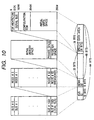
- Fig. 10 is a view showing the addressing of the communication system based on the IEEE 1394 standard.
- IEEE 1394 standard there is defined an address space having a width of 64 bits according to the IEEE 1212 standard.
- the initial 10 bits are called bus ID used for the bus identification.
- Next 6 bits are called node ID, used for identifying various device.
- the remaining 48 bits constitute an address space, usable by each device.
- the addressing of the communication system is managed by the bus management unit provided in the 1394 interface.
- the 48-bit address space mentioned above is further divided into 20 bits and 28 bits, and the initial 20-bit area represented by "FFFFF 16 " is called a register space, which is utilized in the information exchange between the various device.
- the register space further includes a configuration ROM of 1024 bytes and a unit space for storing information specific to each device.
- the configuration ROM is constructed for example as shown in Fig. 11 for representing the function of each node.
- a bus information block 1101 stores a company ID, indicating the supply company of each device.
- a route directory 1102 stores information specific to each device and the storage position of a next unit directory 1103, which stores control/status information relating to the function of each device, and control/status information on the communication protocol supportable by each device in hierarchic manner. Each device can judge the function provided therein and the supported communication protocol by reading the content of the unit directory 1103.
- the printer 902 can print the image taken by the digital camera 901.
- the printer 902 can print the image data by the scanner 204 or image edited by the PC 203.
- the printer 902 can received the image data taken by the digital camera 901 and transfer such data to the PC 203 through the 1394 interface.
- the printer 902 is so constructed as to execute supply to the 1394 interface after the image data transferred according to the communication method based on the IrDA standard are converted into data of a communication method based on the IEEE 1394 standard.
- the digital camera 901 even executing communication by a communication standard different from that of the PC 203 or the scanner 204, can transfer the image data thereto. Consequently the wireless interface communicable with the digital camera 901 need not be equipped in all the devices constituting the communication system of the second embodiment. Also in the second embodiment, the digital camera 901 and the printer 902 mutually communicate by a wireless method, so that the portable device does not lose the mobility and can transfer the image data to the various device without the trouble of cable connection.
- the data communication between the printer 902 and the digital camera 901 is executed by the infrared communication based on the IrDA standard, but such form of communication is restrictive. There may be adopted any communication method as long as it does not deteriorate the features of the portable device such as mobility or compactness.
- the digital camera 901 has been explained as the portable device executing wireless communication with the printer 902, but such example is not restrictive and there may be employed other portable device such as a digital camcorder.
- the configuration shown in Fig. 9 is merely an example and there may be adopted a configuration in which plural device with 1394 interfaces are directly or indirectly connected to the PC 203 and the scanner 204.
- the communication system of the second embodiment is constituted by the printer 902, the PC 203 and the scanner 204, but there may also be employed other digital device such as an external memory such as a hard disk, a CD player or a DVD player, as long as it can constitute a communication system based on the IEEE 1394 standard.
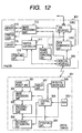
- Fig. 12 is a block diagram showing the structure of the digital camera 901 and the printer 902 shown in Fig. 9.
- the digital camera 901 is composed of an image pickup unit 301, an image processing unit 302, an encoding/decoding unit 303, a recording/reproducing unit 304, an operation unit 305, a control unit 306, a display unit 307, a wireless interface 308 and a ROM 1201.
- the ROM 1201 stores information relating to the function of the digital camera 901.
- the control unit 306 reads the information data stored in the ROM 1201 and sends such data to the printer 902 by wireless communication.
- the printer 902 is provided with a wireless interface 309, an image processing unit 312, a memory 313, a printer head 314, a driver 315, an operation unit 316, a printer controller 317, a power supply unit 318, a 1394 interface 1202, and a data conversion unit 1203.
- the data conversion unit 1203 converts the image data, wireless transmitted from the wireless interface 309, into a data format based on the IEEE 1394 standard, for supply to the 1394 interface 1202, which outputs the image data from the digital camera 901 to the communication system constituted together with the PC 203 and the scanner 204.
- a control command (for controlling the function of the digital camera 901) transferred from the communication system to the digital camera 901 is converted from a communication packet based on the IEEE 1394 standard into a communication packet based on the IrDA standard and supplied to the wireless interface 309.
- the printer 902 is provided with a 1394 interface 1202, and a node ID set by such interface indicates the printer 902 itself.
- the communication packet based on the IEEE 1394 standard is constructed as shown in (b) of Fig. 5, as in the first embodiment.
- the communication packet based on the IrDA standard is constructed as shown in (a) of Fig. 5, as explained in the first embodiment.
- the 1394 interface 1202 is provided therein with a configuration ROM shown in Fig. 11, of which the unit directory 1103 is constructed as shown in Fig. 13.
- a first area 1301 hierarchically stores the control/status information relating to the function of the printer 902 itself and the control/status information relating to the communication protocol supportable by the printer 902.
- a second area 1302 is so constructed as to hierarchically store the control/status information relating to the function of the device capable of communication with the wireless interface 309, namely of the digital camera 901, and the control/status information relating to the communication protocol supportable by the digital camera 901.
- the printer 902 of the second embodiment supports plural communication protocols for transferring the image data for display, recording or printing by the isochronous transfer mode and the asynchronous transfer mode based on the IEEE 1394 standard. Consequently the printer 902 is capable, employing any one of such communication protocols, of transferring the image data, wireless transmitted from the digital camera 901, to a predetermined device on the communication system. The printer 902 is also capable, employing any one of such communication protocols, of transferring the image data, transmitted from a predetermined device on the communication system, to the digital camera 901. Furthermore, the printer 902 is capable, employing a communication protocol for transferring the image data for printing, of printing the image data transmitted from a predetermined device on the communication system.
- the image taken by the image pickup unit 301 is converted into a data format suitable for display in the image processing unit 302, and is then displayed on the display unit 307. If the user manipulates the operation unit 305 to set the digital camera 901 at the recording state, the image taken by the image pickup unit 301 is supplied through the image processing unit 302 to the encoding/decoding unit 303.
- the image data supplied thereto are subjected therein to compression encoding based on the JPEG method and are recorded in the recording medium (not shown) provided in the recording/reproducing unit 304.
- the digital camera 901 reads the desired image from the recording medium provided in the recording/reproducing unit 304.
- the desired image is read by the control of the recording/reproducing unit 304 by the control unit 306 according to the instruction of the user entered through the operation unit 305.
- the encoding/decoding unit 303 executes an expansion decoding process based on the JPEG system, on the image data reproduced from the unrepresented recording medium.
- the image data after expansion decoding are converted into a data format suitable for display in the image processing unit 302 and are displayed on the display unit 307.
- the digital camera 901 sends, by wireless transmission, information relating to the function of the digital camera 901 to the printer 902.
- the function information which is wireless transmitted from the digital camera 901 is received by the wireless interface 309 and is supplied to the printer controller 317.
- the printer controller 317 converts the function information of the digital camera 901 into data based on the IEEE 1394 standard and stores such data in the second area 1302 of the configuration ROM provided in the 1394 interface 1202. After such storage of the function information of the digital camera 901 in the second area 1302, the printer controller 317 requests, to the 1394 interface 1202, execution of bus resetting.
- the 1394 interface 1202 outputs a signal, indicating the start of bus resetting, to the communication system, and executes ID setting for the device constituting the communication system and re-recognition of the connection configuration.
- the device on the communication system can judge the function of the printer 902 and the supported communication protocol by reading the information stored in the first and second areas 1301, 1302 of the unit directory 1103 of the printer 902. In this manner the communication system can recognize the digital camera 901 and the printer 902 as a single device, or the printer 902 itself as a compound device having the function of the digital camera.
- the digital camera 901 can transfer the reproduced desired image data to the printer 902 or a device (for example the PC 203) on the communication system.
- the image data, supplied from the recording/reproducing unit 304 to the wireless interface 308 are converted, in the state of JPEG compression encoded data, int a data format based on the IrDA method and are wireless transmitted to the wireless interface 309 of the printer 902.
- the printer controller 317 so controls the electric power supplied to the 1394 interface 1202 as to ensure the proper function thereof.
- the printer 902 functions as the network printer, thus being capable of communication with any device constituting the communication system, utilizing a predetermined communication protocol.
- the device on the communication system can communicate with the device connected to the wireless interface 309, utilizing the predetermined communication protocol.
- the image data transmitted from the digital camera 901 are supplied from the wireless interface 309 to the 1394 interface 1202, and are converted into a packet of a communication method based on the IEEE 1394 standard, for example the isochronous transfer mode.
- the isochronous packet outputted from the 1394 interface 1202 is transferred to all the device on the communication system. In this state the image data from the 1394 interface 1202 are transferred in the isochronous transfer mode, but can also be transferred to a specified device by the asynchronous transfer mode.
- the printer controller 317 cuts off the power supply to the 1394 interfaces 1202 thereby disabling the communicating function thereof.
- the 1394 interface provided in each device on the communication system identifies that the printer 902 is separated from the communication system and automatically recognizes again the configuration of the communication system excluding the printer 902.
- the printer 902 itself enables the communicating function of the wireless interface 309 only, and executes communication with the device capable of communicating with the wireless interface 309. Consequently the image data transmitted from the digital camera 901 are supplied only to the image processing unit 312.
- the 1394 interface provided in each device detects the addition or deletion of a device to or from the communication system by the change of the bias voltage supplied to the communication cable. Therefore, in case of the function as the direct printer, the printer 902 completely cuts off the electric power supply to the 1394 interfaces 1202, thereby terminating all the functions relating to the communication of the 1394 interface 1202 and terminating the bias voltage supply to the communication cable.
- the image processing unit 312 decodes the JPEG compression encoded image data, utilizing a JPEG decoding program file stored in an unrepresented ROM or decoding data transmitted from the digital camera 901 together with the compressed image data. Also the image processing unit 312 converts the decoded image data into a data format, suitable for printing, utilizing the memory 313 and stores the converted data in the memory 313. The image data stored in the memory 313 are supplied to the printer head 216 and printed therein.
- the printing operation is rendered possible by supplying the image processing unit 312 with the data entered from the 1394 interface 1202.
- the function of the direct printer or the network printer is set by the entry of an instruction into the operation unit 305 or 306 of the digital camera 901 or the printer 902.
- the communication system of the second embodiment can recognize the device executing communication by a communication standard different from that of the communication system, as a constituting device and can execute the data communication with such device by the communication method same as that of the communication system.
- the communication system of the second embodiment can recognize the printer 902 as a compound device provided with the function of the digital camera 901.
- the printer 902 can utilize the printer 902 independently as the network printer or as the direct printer, by controlling the power supply to the 1394 interface equipped in the printer 902. In case of function as the direct printer, the printer 902 can execute rapid data communication without being influenced by the communication in the communication system.
- the JPEG compressed image data are transferred from the digital camera 901 to the printer 902 and decoded therein to achieve an improved transfer efficiency in comparison with the case of transfer of the non-compressed image data.
- the decoding process corresponding to the JPEG method can be achieved either by a hardware, namely by a JPEG decoding circuit (board) or by a software.
- the printer 902 itself may be provided therein with a decoder without difficulty in cost and with an advantage of compactization of circuitry.
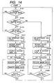
- FIG. 14 is a flow chart showing the functions of the communication system of the second embodiment shown in Fig. 9.
- the digital camera 901 of the second embodiment is provided, as in the first embodiment, with a switch 601 for switching the plural operation modes of the digital camera 901.
- the switch 601 is constructed as shown in Fig. 6.
- the digital camera 901 does not execute communication with the printer 902 (step S1401).
- the printer 902 functions as the network printer, capable of communication solely with the communication system excluding the digital camera 901.
- the printer 902 enables the function of the 1394 interface 1202 and the wireless interface 309 and constantly monitors the change in the operation mode of the digital camera 901.
- the printer 902 identifies the "normal operation mode” from the control data transmitted from the digital camera 901, but there may also be adopted a configuration allowing direct entry of control data indicating the "normal operation mode” from the operation unit 316 of the printer 902. It is also possible to provide the printer 902 with timer means for measuring the time after the termination of the communication with the digital camera 901 and to automatically identify the "normal operation mode" after the lapse of a predetermined time.
- the digital camera 901 transmits control data indicating the "direct printer mode” to the printer 902 (step S1402).
- the printer 902 for executing data communication with the digital camera 901, controls the power supply unit 318 to disable the function of the 1394 interfaces 1202 of the printer 902 (step S1403).
- the printer 902 After the reception of the control data indicating the "direct printer mode", the printer 902 receives the information relating to the function of the digital camera 901 (step S1404).
- the printer 902 converts the content of the information into control/status information based on the IEEE 1394 standard and stores the converted information in the second area 1302 of the unit directory 1103 (step S1405).
- the 1394 interface 1202 After the storage of the information on the digital camera 901 in the second area 1302, the 1394 interface 1202 requests bus resetting to the communication system, and executes re-recognition of the connection configuration (step S1406), whereby the communication system automatically recognizes that the printer 902 is disconnected from the network.
- the printer 902 receives the image data which are wireless transmitted from the digital camera 901, and sends such image data to the image processing unit 312 (step S1407), and the printer 902 prints the image data, converted into a printable format by the image processing unit 312 (step S1408). Also in case of printing other image data of the digital camera 901, the user manipulates the operation unit 305 of the digital camera 901 to transmit such image data (step S1409). In this manner the printer 902 can communicate solely with the digital camera 901 without being influenced by the communication on the communication system, so that the user can preferentially execute the output from the digital camera 901. Also the present embodiment executes control in such a manner that the printer 902 functions as the direct printer in response to the control data transmitted from the digital camera 901, but the system may also be so constructed as to execute such control in response to the input from the operation unit 316.
- the digital camera 901 transmits control data indicating such operation mode (step S1410).
- the printer 902 controls the power supply unit 318 to enable the function of the 1394 interface 1202 of the printer 902 in order to execute data communication with the communication system including the digital camera 901 (step S1411).
- the printer 902 After the reception of the control data indicating the "network mode", the printer 902 receives information relating to the function of the digital camera (step S1412). The printer 902 converts the content of such function information into control/status information based on the IEEE 1394 standard and stores it in the second area 1302 of the unit directory 1103 (step S1413).
- the 1394 interface 1202 After the storage of the information on the digital camera 901 in the second area 1302, the 1394 interface 1202 requests bus resetting to the communication system, and executes re-recognition of the connection configuration (step S1414), whereby the communication system can recognize the printer 902 as a compound device provided with the function of the digital camera 901.
- the printer 902 receives the compressed image data, sent by wireless transmission from the digital camera 901, then converts the compressed image data into a communication packet of the isochronous transfer mode and transfers it to the PC 203 (steps S1415, S1416).
- the PC 203 receives the communication packet transferred by the isochronous transfer mode, memorizes the compressed image data contained in the communication packet and applies thereto image processing such as image editing. Also in case of transferring other image data to the PC 203, the user manipulates the operation unit 305 of the digital camera 901 to transmit such image data (step S1417). In the present embodiment, there may also be adopted a configuration of selecting and designating the image taken by the digital camera 901 by transmitting a control command for the digital camera 901 from the PC 203.
- the 1394 interface 1202 of the present embodiment converts the image data, transmitted from the digital camera 901, into the communication packet of the isochronous transfer mode, but the image data may also converted into a communication packet of the asynchronous transfer mode by designating the destination of communication in the digital camera 901.
- the PC 203 is selected as the destination of communication, but there may be selected any device on the communication system.
- the printer 902 is so controlled as to function as the network printer according to the control data transmitted from the digital camera 901, but such control may also be achieved according to an input from the operation unit 316.
- the above-explained configuration allows to control the function of the printer 902 according to the operation mode of the digital camera 901, thereby realizing an optimum network configuration for the digital camera 901 and the printer 902. More specifically, in case the digital camera 901 is in the "normal operation mode” (in the power-off state, in the image pickup state or in the image reproducing state) or in the "network mode", the printer 902 can function as the network printer. Also in case the digital camera 901 is in the "direct printer mode", the printer 902 can function as the direct printer.
- the above-described configuration enables to connect the digital camera 901 without the 1394 interface to the communication system based on the IEEE 1394 standard, and to cause such communication system to recognize the printer 902 as a compound device provided with the function of the digital camera 901. Consequently the digital camera 901 can transmit the taken image data to a specified device or all the device on the communication system, and the digital camera 901 can be controlled from any device on the communication system.
- the second embodiment of the present invention allows a device of a communication standard different from that, for example the IEEE 1394 standard, of the communication system to be recognized as a constituent device of such communication system.
- a device provided with plural communication interfaces is rendered capable of prompt data communication with a specified external device without being influenced by the communication with other device, by disabling communication other than with such specified external device according to the operation state thereof.
- the communication system shown in the first and second embodiments is composed of the communication interfaces based on the IEEE 1394 standard, but such configuration is not restrictive.
- the communication system may be based on the USB (universal serial bus) standard, as long as the system is capable of automatic setting of the ID information of the device constituting the communication system and automatic recognition of the connection configuration thereof as in the IEEE 1394 standard.
- the processes of the constituting device may be realized with a software.
- a control unit including a microcomputer
- a memory medium which records program codes of a software realizing the functions of the foregoing embodiments.
- the embodiments of the present invention can be attained by a configuration in which the control unit provided in the system or the apparatus of the foregoing embodiments reads the program codes stored in the recording medium and controls the function of such system or apparatus so as to attain the functions of the above-described embodiments.
- program codes realizing the process and function of the first embodiment shown in Fig. 8 or the second embodiment shown in Fig. 14 are stored in a memory provided in the printer controller 317 shown in Fig. 3 or 12, and the control unit 306 or the printer controller 317 reads such program codes and to operate the process circuits of the printer 202 or 902 shown in Fig. 3 or 12 so as to realize the functions of the respective embodiment.
- the memory medium for supplying the program codes may be composed, for example, of a floppy disk, a hard disk, an optical disk, a magnetooptical disk, a CD-ROM, a CD-R, a magnetic tape, a non-volatile memory card or a ROM.
- the present invention naturally includes a case in which an OS (operating system) or an application software functioning on the control unit controls the functions of the system or the apparatus of the foregoing embodiments according to the instructions of the program codes read from the memory medium, thereby realizing the functions of the foregoing embodiments.
- OS operating system
- application software functioning on the control unit controls the functions of the system or the apparatus of the foregoing embodiments according to the instructions of the program codes read from the memory medium, thereby realizing the functions of the foregoing embodiments.
- the present invention naturally includes a case in which the program codes read from the memory medium are stored in a memory provided in a function expanding board or a function expanding unit connected to the control unit, and a control unit provided in such function expanding board or unit controls the functions of the system or apparatus of the foregoing embodiments according to the instructions of such program codes, thereby realizing the functions of the foregoing embodiments.
Claims (17)
- Imprimante comprenant :un pilote d'imprimante (305) connectable à un premier et un second moyens de communication respectifs (311, 309) utilisables en ce qui concerne différents dispositifs externes et possédant un premier et un second protocoles de communication différents respectifs etcaractérisé en ce que l'imprimante comprend de plus un moyen de commande d'imprimante (317) configuré pour commander ledit premier et second moyens de communication en ce qui concerne le premier et le second modes de fonctionnement grâce à quoi, dans le premier mode de fonctionnement, un premier dispositif externe relié au premier moyen de communication peut reconnaître la présence d'un, et coopérer avec un, second dispositif externe relié au second moyen de communication et avec l'imprimante elle-même de telle manière que l'imprimante peut fonctionner comme une imprimante réseau ou, dans le second mode de fonctionnement, pour autoriser seulement un dispositif externe connecté au second moyen de communication à échanger des données avec l'imprimante grâce à quoi l'imprimante agit, dans le second mode de fonctionnement, comme une imprimante directe pour ledit second dispositif externe.
- Imprimante selon la revendication 1, dans laquelle le premier moyen de communication comprend une interface conforme à la norme IEEE 1394 et reliée au pilote d'imprimante.
- Imprimante selon la revendication 1 ou la revendication 2, dans laquelle le second moyen de communication comprend une interface sans fil correspondant à la norme IrDA .
- Imprimante selon la revendication 1, dans laquelle le premier moyen de communication comprend une première interface (311) conforme à la norme IEEE 1394 et reliée à l'imprimante, dans laquelle le second moyen de communication comprend une interface sans fil (309) correspondant à la norme IrDA, et dans laquelle l'interface sans fil est reliée à une seconde interface (310) conforme à la norme IEEE 1394 et reliée à la première interface.
- Imprimante selon la revendication 4 dans laquelle, dans le second mode de fonctionnement, le moyen de commande d'imprimante agit pour désactiver la première interface conforme à la norme IEEE 1394.
- Imprimante selon la revendication 1, dans laquelle le premier moyen de communication comprend une première interface (1202) conforme à la norme IEEE 1394 et reliée à l'imprimante, dans laquelle le second moyen de communication comprend une interface sans fil (309) correspondant à la norme IrDA et dans laquelle le moyen de commande d'imprimante est configuré pour désactiver la première interface pour fournir le second mode de fonctionnement et, dans le premier mode de fonctionnement, pour activer la première interface de manière que l'imprimante et un dispositif externe relié au second moyen de communication agissent ensemble comme un noeud réseau.
- Imprimante selon la revendication 6, dans laquelle l'interface sans fil est reliée à un moyen de conversion de données (1203) destiné à convertir des données provenant de l'interface sans fil en données conformes au premier moyen de communication et destiné à convertir des données provenant de l'imprimante ou provenant d'un dispositif externe relié au premier moyen de communication en données conformes au second moyen de communication.
- Système comprenant une imprimante selon l'une quelconque des revendications précédentes en combinaison avec une caméra numérique possédant un moyen de communication compatible avec le second moyen de communication de l'imprimante.
- Procédé mis en oeuvre dans une imprimante, les étapes réalisées par ladite imprimante comprenant :le pilotage d'un pilote d'imprimante (305) relié aux premier et second moyens de communication respectifs (311, 309) utilisables en ce qui concerne différents dispositifs externes et possédant un premier et un second protocoles de communication différents respectifs et caractérisé par le fait que l'imprimante fait de plus fonctionner un moyen de commande d'imprimante (317) commandant lesdits premier et second moyens de communication en ce qui concerne le premier et le second mode de fonctionnement grâce à quoi, dans le premier mode de fonctionnement, un premier dispositif externe relié au premier moyen de communication reconnaît la présence d'un, et coopère avec un, second dispositif externe relié au second moyen de communication et avec l'imprimante elle-même de telle manière que l'imprimante peut fonctionner comme une imprimante réseau ou, dans le second mode de fonctionnement, autorise seulement un dispositif externe relié au second moyen de communication à échanger des données avec l'imprimante, grâce à quoi l'imprimante agit, dans le second mode de fonctionnement, comme une imprimante directe pour ledit second dispositif externe.
- Procédé selon la revendication 9, dans lequel le premier moyen de communication comprend une interface conforme à la norme IEEE 1394 et reliée au pilote d'imprimante.
- Procédé selon la revendication 9 ou la revendication 10, dans lequel le second moyen de communication comprend une interface sans fil correspondant à la norme IrDA.
- Procédé selon la revendication 9, dans lequel le premier moyen de communication comprend une première interface (311) conforme à la norme IEEE 1394 et reliée à l'imprimante, dans lequel le second moyen de communication comprend une interface sans fil (309) correspondant à la norme IrDA et dans lequel l'interface sans fil est reliée à une seconde interface (310) conforme à la norme IEEE 1394 et reliée à la première interface.
- Procédé selon la revendication 12 dans lequel, dans le second mode de fonctionnement, le moyen de commande de l'imprimante agit pour désactiver la première interface conforme à la norme IEEE 1394.
- Procédé selon la revendication 9, dans lequel le premier moyen de communication comprend une première interface (1202) conforme à la norme IEEE 1394 et reliée à l'imprimante, dans lequel le second moyen de communication comprend une interface sans fil (309) correspondant à la norme IrDA, et dans lequel le moyen de commande de l'imprimante est configuré pour désactiver la première interface pour fournir le second mode de fonctionnement et, dans le premier mode de fonctionnement, pour activer la première interface de telle manière que l'imprimante et un dispositif externe relié au second moyen de communication agissent ensemble comme un noeud réseau.
- Procédé selon la revendication 14, dans lequel l'interface sans fil est reliée à un moyen de conversion de données (1203) destiné à convertir des données provenant de l'interface sans fil en données conformes au premier moyen de communication et pour convertir des données provenant de l'imprimante ou provenant d'un dispositif externe relié au premier moyen de communication en données conformes au second moyen de communication.
- Procédé selon l'une quelconque des revendications 9 à 15, dans lequel l'imprimante coopère avec une caméra numérique possédant un moyen de communication compatible avec le second moyen de communication de l'imprimante.
- Support de stockage stockant des instructions exécutables par un processeur destinées à commander un processeur électronique pour exécuter toutes les étapes d'un procédé selon l'une quelconque des revendications 9 à 16.
Applications Claiming Priority (6)
| Application Number | Priority Date | Filing Date | Title |
|---|---|---|---|
| JP05760697A JP3880123B2 (ja) | 1997-03-12 | 1997-03-12 | データ通信装置 |
| JP5760697 | 1997-03-12 | ||
| JP57606/97 | 1997-03-12 | ||
| JP51954/98 | 1998-03-04 | ||
| JP5195498A JP4018226B2 (ja) | 1998-03-04 | 1998-03-04 | データ通信装置 |
| JP5195498 | 1998-03-04 |
Publications (3)
| Publication Number | Publication Date |
|---|---|
| EP0864986A2 EP0864986A2 (fr) | 1998-09-16 |
| EP0864986A3 EP0864986A3 (fr) | 1999-11-17 |
| EP0864986B1 true EP0864986B1 (fr) | 2006-07-12 |
Family
ID=26392547
Family Applications (1)
| Application Number | Title | Priority Date | Filing Date |
|---|---|---|---|
| EP98301792A Expired - Lifetime EP0864986B1 (fr) | 1997-03-12 | 1998-03-11 | Dispositif, procédé et système de communication de données et programme pour traitement de communication de données dans un support de mémoire |
Country Status (3)
| Country | Link |
|---|---|
| US (1) | US6529522B1 (fr) |
| EP (1) | EP0864986B1 (fr) |
| DE (1) | DE69835179T2 (fr) |
Families Citing this family (87)
| Publication number | Priority date | Publication date | Assignee | Title |
|---|---|---|---|---|
| US6786420B1 (en) | 1997-07-15 | 2004-09-07 | Silverbrook Research Pty. Ltd. | Data distribution mechanism in the form of ink dots on cards |
| US6618117B2 (en) | 1997-07-12 | 2003-09-09 | Silverbrook Research Pty Ltd | Image sensing apparatus including a microcontroller |
| US6624848B1 (en) | 1997-07-15 | 2003-09-23 | Silverbrook Research Pty Ltd | Cascading image modification using multiple digital cameras incorporating image processing |
| US6690419B1 (en) | 1997-07-15 | 2004-02-10 | Silverbrook Research Pty Ltd | Utilising eye detection methods for image processing in a digital image camera |
| US6879341B1 (en) | 1997-07-15 | 2005-04-12 | Silverbrook Research Pty Ltd | Digital camera system containing a VLIW vector processor |
| US7110024B1 (en) | 1997-07-15 | 2006-09-19 | Silverbrook Research Pty Ltd | Digital camera system having motion deblurring means |
| US7551201B2 (en) | 1997-07-15 | 2009-06-23 | Silverbrook Research Pty Ltd | Image capture and processing device for a print on demand digital camera system |
| JP2000059459A (ja) * | 1998-08-11 | 2000-02-25 | Canon Inc | データ通信装置、データ通信システム、データ通信方法、及び記憶媒体 |
| AUPP702098A0 (en) | 1998-11-09 | 1998-12-03 | Silverbrook Research Pty Ltd | Image creation method and apparatus (ART73) |
| EP0991070A3 (fr) * | 1998-09-18 | 2003-07-23 | Matsushita Electric Industrial Co., Ltd. | Système d'édition pour audio et vidéo |
| AUPP702198A0 (en) * | 1998-11-09 | 1998-12-03 | Silverbrook Research Pty Ltd | Image creation method and apparatus (ART79) |
| JP3335586B2 (ja) * | 1998-11-16 | 2002-10-21 | 松下電器産業株式会社 | デジタル情報編集システム |
| WO2000031958A1 (fr) * | 1998-11-23 | 2000-06-02 | Siemens Aktiengesellschaft | Appareil d'impression pour la sortie de donnees d'image d'un appareil photo numerique |
| US6819677B1 (en) * | 1999-02-08 | 2004-11-16 | Sigmatel, Inc. | Method and apparatus for recovering data that was transported utilizing multiple data transport protocols |
| JP3353824B2 (ja) * | 1999-04-22 | 2002-12-03 | 日本電気株式会社 | ネットワーク同期システム及びネットワーク同期方法 |
| JP3876588B2 (ja) * | 1999-05-24 | 2007-01-31 | セイコーエプソン株式会社 | プリンタ、プリンタの制御方法およびプリントシステム並びに記録媒体 |
| AUPQ056099A0 (en) | 1999-05-25 | 1999-06-17 | Silverbrook Research Pty Ltd | A method and apparatus (pprint01) |
| US6439706B1 (en) * | 1999-05-25 | 2002-08-27 | Silverbrook Research Pty Ltd. | Printer cartridge with binder |
| SG97915A1 (en) * | 1999-08-19 | 2003-08-20 | Sony Corp | Image processing method and apparatus, printing method and apparatus, image printing system and method and recording medium |
| US6691096B1 (en) | 1999-10-28 | 2004-02-10 | Apple Computer, Inc. | General purpose data container method and apparatus for implementing AV/C descriptors |
| US6618750B1 (en) | 1999-11-02 | 2003-09-09 | Apple Computer, Inc. | Method and apparatus for determining communication paths |
| US6813663B1 (en) * | 1999-11-02 | 2004-11-02 | Apple Computer, Inc. | Method and apparatus for supporting and presenting multiple serial bus nodes using distinct configuration ROM images |
| JP4265053B2 (ja) * | 1999-11-04 | 2009-05-20 | ソニー株式会社 | デジタル放送受信システム、デジタル放送受信装置、受信装置、印刷装置、並びに印刷方法 |
| US6587904B1 (en) * | 1999-11-05 | 2003-07-01 | Apple Computer, Inc. | Method and apparatus for preventing loops in a full-duplex bus |
| US6636914B1 (en) | 1999-11-05 | 2003-10-21 | Apple Computer, Inc. | Method and apparatus for arbitration and fairness on a full-duplex bus using dual phases |
| JP4192372B2 (ja) * | 1999-12-03 | 2008-12-10 | ソニー株式会社 | 印刷装置、印刷制御装置、印刷システム及び印刷方法 |
| US6639918B1 (en) | 2000-01-18 | 2003-10-28 | Apple Computer, Inc. | Method and apparatus for border node behavior on a full-duplex bus |
| US7266617B1 (en) | 2000-01-18 | 2007-09-04 | Apple Inc. | Method and apparatus for border node behavior on a full-duplex bus |
| JP2001202228A (ja) * | 2000-01-19 | 2001-07-27 | Sony Corp | 印刷制御方法及び伝送制御装置 |
| US7050453B1 (en) * | 2000-02-17 | 2006-05-23 | Apple Computer, Inc. | Method and apparatus for ensuring compatibility on a high performance serial bus |
| CA2403270C (fr) * | 2000-03-14 | 2011-05-17 | Joseph Robert Marchese | Systeme video numerique utilisant des cameras reseautees |
| JP2001298694A (ja) * | 2000-04-13 | 2001-10-26 | Konica Corp | 撮像装置、画像記録システム、画像記録装置及び出力特性補正方法 |
| US6718497B1 (en) | 2000-04-21 | 2004-04-06 | Apple Computer, Inc. | Method and apparatus for generating jitter test patterns on a high performance serial bus |
| US6618785B1 (en) * | 2000-04-21 | 2003-09-09 | Apple Computer, Inc. | Method and apparatus for automatic detection and healing of signal pair crossover on a high performance serial bus |
| JP2003533944A (ja) * | 2000-05-15 | 2003-11-11 | トムソン ライセンシング ソシエテ アノニム | 等時性のリソースを無線ネットワークに確保するための方法 |
| US6990548B1 (en) * | 2000-06-15 | 2006-01-24 | Hewlett-Packard Development Company, L.P. | Methods and arrangements for configuring a printer over a wireless communication link using a wireless communication device |
| US6912060B1 (en) * | 2000-07-05 | 2005-06-28 | Lexmark International, Inc. | Photoprinter control of peripheral devices |
| US6636259B1 (en) | 2000-07-26 | 2003-10-21 | Ipac Acquisition Subsidiary I, Llc | Automatically configuring a web-enabled digital camera to access the internet |
| US8224776B1 (en) | 2000-07-26 | 2012-07-17 | Kdl Scan Designs Llc | Method and system for hosting entity-specific photo-sharing websites for entity-specific digital cameras |
| US7287088B1 (en) | 2000-10-06 | 2007-10-23 | Fotomedia Technologies, Llc | Transmission bandwidth and memory requirements reduction in a portable image capture device by eliminating duplicate image transmissions |
| US7805720B2 (en) | 2003-04-11 | 2010-09-28 | Flexiworld Technologies, Inc. | Autorun for integrated circuit memory component |
| US10860290B2 (en) | 2000-11-01 | 2020-12-08 | Flexiworld Technologies, Inc. | Mobile information apparatuses that include a digital camera, a touch sensitive screen interface, support for voice activated commands, and a wireless communication chip or chipset supporting IEEE 802.11 |
| US11204729B2 (en) | 2000-11-01 | 2021-12-21 | Flexiworld Technologies, Inc. | Internet based digital content services for pervasively providing protected digital content to smart devices based on having subscribed to the digital content service |
| US11467856B2 (en) | 2002-12-12 | 2022-10-11 | Flexiworld Technologies, Inc. | Portable USB device for internet access service |
| CN100334577C (zh) | 2000-11-01 | 2007-08-29 | 福来西奥德技术公司 | 用于设备到设备的普适数字输出的控制器及管理器 |
| US10915296B2 (en) | 2000-11-01 | 2021-02-09 | Flexiworld Technologies, Inc. | Information apparatus that includes a touch sensitive screen interface for managing or replying to e-mails |
| US20020078101A1 (en) | 2000-11-20 | 2002-06-20 | Chang William Ho | Mobile and pervasive output client device |
| US7272788B2 (en) * | 2000-12-29 | 2007-09-18 | Fotomedia Technologies, Llc | Client-server system for merging of metadata with images |
| US7197531B2 (en) * | 2000-12-29 | 2007-03-27 | Fotomedia Technologies, Llc | Meta-application architecture for integrating photo-service websites for browser-enabled devices |
| US20020097418A1 (en) | 2001-01-19 | 2002-07-25 | Chang William Ho | Raster image processor and processing method for universal data output |
| AU2002241315A1 (en) * | 2001-03-30 | 2002-10-21 | Canon Kabushiki Kaisha | File management method |
| US7515288B2 (en) * | 2001-04-06 | 2009-04-07 | Sharp Kabushiki Kaisha | Image processing apparatus |
| WO2002098130A2 (fr) * | 2001-05-31 | 2002-12-05 | Canon Kabushiki Kaisha | Appareil de stockage d'information et procede associe |
| JP4054555B2 (ja) * | 2001-10-01 | 2008-02-27 | キヤノン株式会社 | 記録装置及びその制御方法及び記録媒体 |
| JP3809403B2 (ja) * | 2002-07-16 | 2006-08-16 | キヤノン株式会社 | 撮像装置、外部処理装置、撮像装置のための制御プログラム、外部処理装置のための制御プログラム |
| US7480083B2 (en) * | 2002-07-30 | 2009-01-20 | Canon Kabushiki Kaisha | Image processing system, apparatus, and method, and color reproduction method |
| US8605334B2 (en) * | 2002-08-05 | 2013-12-10 | Canon Kabushiki Kaisha | Recording system, recording apparatus, and control method therefor |
| US20040042033A1 (en) * | 2002-08-28 | 2004-03-04 | Bob Sesek | Display of location of alternate image-forming device to which image-forming-related job has been routed |
| US20040051894A1 (en) * | 2002-09-16 | 2004-03-18 | Xerox Corporation | Portable input scanning device in communication with a multi-function document services machine |
| WO2004047376A1 (fr) * | 2002-11-18 | 2004-06-03 | Sharp Kabushiki Kaisha | Dispositif et programme de relais de reseau, support d'enregistrement contenant ce programme de relais de reseau |
| AU2003300880A1 (en) | 2002-12-12 | 2004-07-09 | Flexiworld Technologies, Inc. | Wireless communication between computing devices |
| CN1302659C (zh) * | 2003-03-27 | 2007-02-28 | 三星电子株式会社 | 数字成像装置和用于选择它的数据传输模式的方法 |
| JP4125173B2 (ja) * | 2003-04-23 | 2008-07-30 | キヤノン株式会社 | 情報処理装置の接続制御方法、情報処理装置、及びコンピュータプログラム |
| JP4125172B2 (ja) * | 2003-04-23 | 2008-07-30 | キヤノン株式会社 | 無線通信システム、無線通信装置、及びその制御方法、並びにコンピュータプログラム |
| JP4136771B2 (ja) * | 2003-04-23 | 2008-08-20 | キヤノン株式会社 | 通信システム、通信装置、及びその制御方法、並びにコンピュータプログラム |
| JP2007528563A (ja) * | 2003-05-09 | 2007-10-11 | エルジー エレクトロニクス インコーポレーテッド | 記録媒体の少なくともデータ領域を管理するためのデータ構造を有する記録媒体、並びに記録再生方法及び装置 |
| US7668099B2 (en) | 2003-06-13 | 2010-02-23 | Apple Inc. | Synthesis of vertical blanking signal |
| US7353284B2 (en) | 2003-06-13 | 2008-04-01 | Apple Inc. | Synchronized transmission of audio and video data from a computer to a client via an interface |
| US8275910B1 (en) | 2003-07-02 | 2012-09-25 | Apple Inc. | Source packet bridge |
| US7809728B2 (en) * | 2003-07-09 | 2010-10-05 | Canon Kabushiki Kaisha | Recording/playback apparatus and method |
| US7788567B1 (en) * | 2003-11-18 | 2010-08-31 | Apple Inc. | Symbol encoding for tolerance to single byte errors |
| US7995606B1 (en) | 2003-12-03 | 2011-08-09 | Apple Inc. | Fly-by and ack-accelerated arbitration for broadcast packets |
| US7502338B1 (en) | 2003-12-19 | 2009-03-10 | Apple Inc. | De-emphasis training on a point-to-point connection |
| US7308517B1 (en) * | 2003-12-29 | 2007-12-11 | Apple Inc. | Gap count analysis for a high speed serialized bus |
| US7237135B1 (en) * | 2003-12-29 | 2007-06-26 | Apple Inc. | Cyclemaster synchronization in a distributed bridge |
| US20050254085A1 (en) * | 2004-05-12 | 2005-11-17 | Koji Oshikiri | Image forming system |
| DE102004045118A1 (de) * | 2004-09-17 | 2006-03-23 | Robert Bosch Gmbh | Verfahren und Vorrichtung zur Datenübertragung |
| US20060143684A1 (en) * | 2004-12-29 | 2006-06-29 | Morris Robert P | Method and system for allowing a user to specify actions that are to be automatically performed on data objects uploaded to a server |
| US20060143607A1 (en) * | 2004-12-29 | 2006-06-29 | Morris Robert P | Method and system for allowing a user to create actions to be taken by a server |
| JP4502389B2 (ja) * | 2005-03-15 | 2010-07-14 | キヤノン株式会社 | 通信装置及びその制御方法 |
| JP4356997B2 (ja) * | 2005-03-15 | 2009-11-04 | キヤノン株式会社 | 通信装置及びその通信方法 |
| JP4366323B2 (ja) * | 2005-03-15 | 2009-11-18 | キヤノン株式会社 | 通信装置およびその制御方法 |
| JP4777106B2 (ja) * | 2006-03-22 | 2011-09-21 | キヤノン株式会社 | 通信装置及び無線通信の制御方法 |
| US9166883B2 (en) | 2006-04-05 | 2015-10-20 | Joseph Robert Marchese | Network device detection, identification, and management |
| US8483108B2 (en) * | 2006-07-24 | 2013-07-09 | Apple Inc. | Apparatus and methods for de-emphasis training on a point-to-point connection |
| JP4886463B2 (ja) | 2006-10-20 | 2012-02-29 | キヤノン株式会社 | 通信パラメータ設定方法、通信装置及び通信パラメータを管理する管理装置 |
| JP2012070111A (ja) * | 2010-09-22 | 2012-04-05 | Fuji Xerox Co Ltd | 通信システム |
Family Cites Families (5)
| Publication number | Priority date | Publication date | Assignee | Title |
|---|---|---|---|---|
| CA1286417C (fr) * | 1986-07-24 | 1991-07-16 | Junichi Ohta | Methode et appareil de generation de donnees d'identification |
| CA2119334C (fr) * | 1993-04-07 | 2006-11-07 | Laroy Tymes | Protocole de systeme de transmission de donnees par paquets |
| JP3073284B2 (ja) * | 1991-10-08 | 2000-08-07 | 三菱重工業株式会社 | データ通信方式 |
| JP3318635B2 (ja) * | 1994-02-24 | 2002-08-26 | ソニー株式会社 | 電子機器及び通信方法 |
| JP3442593B2 (ja) * | 1996-11-20 | 2003-09-02 | 株式会社東芝 | ネットワーク接続装置及びネットワーク接続方法 |
-
1998
- 1998-03-11 EP EP98301792A patent/EP0864986B1/fr not_active Expired - Lifetime
- 1998-03-11 DE DE69835179T patent/DE69835179T2/de not_active Expired - Lifetime
- 1998-03-12 US US09/041,122 patent/US6529522B1/en not_active Expired - Fee Related
Also Published As
| Publication number | Publication date |
|---|---|
| EP0864986A3 (fr) | 1999-11-17 |
| EP0864986A2 (fr) | 1998-09-16 |
| DE69835179D1 (de) | 2006-08-24 |
| DE69835179T2 (de) | 2007-07-05 |
| US6529522B1 (en) | 2003-03-04 |
Similar Documents
| Publication | Publication Date | Title |
|---|---|---|
| EP0864986B1 (fr) | Dispositif, procédé et système de communication de données et programme pour traitement de communication de données dans un support de mémoire | |
| CA2229472C (fr) | Appareil et methode de transmission de donnees | |
| US6298405B1 (en) | Data communication system, printing system and data communication apparatus | |
| EP0977431B1 (fr) | Système de contrôle dans lequel les conditions de contrôle entre un dispositif de prise de vues et un ordinateur personnel peuvent être choisies librement | |
| US6580460B1 (en) | System connecting power supply line to image sensing device upon data transport | |
| US7062579B2 (en) | Data transmission apparatus, system and method, and image processing apparatus | |
| KR100394423B1 (ko) | 통신장치및그처리방법 | |
| EP0853284B1 (fr) | Système comprenant une imprimante et une caméra et procédé d'impession | |
| US6237106B1 (en) | Communication apparatus and method, and program in computer readable medium | |
| US7535490B2 (en) | Imaging apparatus having control modes switchable based on connection to another apparatus | |
| JP2002009864A (ja) | 制御方法及び通信装置 | |
| US20060170779A1 (en) | Image data transfer system, method of generating image data file, and computer program | |
| US20040189811A1 (en) | Print system, printer, and printer controlling device | |
| KR100329162B1 (ko) | 데이터 전송 방법 및 데이터 전송 시스템 | |
| US7443530B2 (en) | Electronic apparatus, image forming system, video printing system and camera-incorporated recording/reproducing apparatus | |
| JPH10257119A (ja) | データ通信装置及び方法 | |
| JP4018226B2 (ja) | データ通信装置 | |
| US20060017811A1 (en) | Communication system, electronic apparatus, control apparatus, and computer-readable storage medium | |
| US6816993B1 (en) | Control method of electronic device controllable from external control apparatus by communication | |
| JP3912908B2 (ja) | プリンタ、プリント方法および記録媒体 | |
| JPH10229538A (ja) | データ通信システム、プリントシステム及びデータ通信装置 | |
| JP3774540B2 (ja) | データ転送方法及び画像処理システムと装置 | |
| JP4491956B2 (ja) | 通信方法、通信システム及び通信装置 | |
| JP2006287945A (ja) | 印刷装置 | |
| JP4367069B2 (ja) | 電源制御装置 |
Legal Events
| Date | Code | Title | Description |
|---|---|---|---|
| PUAI | Public reference made under article 153(3) epc to a published international application that has entered the european phase |
Free format text: ORIGINAL CODE: 0009012 |
|
| AK | Designated contracting states |
Kind code of ref document: A2 Designated state(s): DE FR GB NL |
|
| AX | Request for extension of the european patent |
Free format text: AL;LT;LV;MK;RO;SI |
|
| PUAL | Search report despatched |
Free format text: ORIGINAL CODE: 0009013 |
|
| AK | Designated contracting states |
Kind code of ref document: A3 Designated state(s): AT BE CH DE DK ES FI FR GB GR IE IT LI LU MC NL PT SE |
|
| AX | Request for extension of the european patent |
Free format text: AL;LT;LV;MK;RO;SI |
|
| 17P | Request for examination filed |
Effective date: 20000403 |
|
| AKX | Designation fees paid |
Free format text: DE FR GB NL |
|
| 17Q | First examination report despatched |
Effective date: 20040112 |
|
| GRAP | Despatch of communication of intention to grant a patent |
Free format text: ORIGINAL CODE: EPIDOSNIGR1 |
|
| GRAS | Grant fee paid |
Free format text: ORIGINAL CODE: EPIDOSNIGR3 |
|
| GRAA | (expected) grant |
Free format text: ORIGINAL CODE: 0009210 |
|
| AK | Designated contracting states |
Kind code of ref document: B1 Designated state(s): DE FR GB NL |
|
| REG | Reference to a national code |
Ref country code: GB Ref legal event code: FG4D |
|
| REF | Corresponds to: |
Ref document number: 69835179 Country of ref document: DE Date of ref document: 20060824 Kind code of ref document: P |
|
| PLBE | No opposition filed within time limit |
Free format text: ORIGINAL CODE: 0009261 |
|
| STAA | Information on the status of an ep patent application or granted ep patent |
Free format text: STATUS: NO OPPOSITION FILED WITHIN TIME LIMIT |
|
| 26N | No opposition filed |
Effective date: 20070413 |
|
| PGFP | Annual fee paid to national office [announced via postgrant information from national office to epo] |
Ref country code: FR Payment date: 20100414 Year of fee payment: 13 |
|
| PGFP | Annual fee paid to national office [announced via postgrant information from national office to epo] |
Ref country code: NL Payment date: 20100315 Year of fee payment: 13 |
|
| REG | Reference to a national code |
Ref country code: NL Ref legal event code: V1 Effective date: 20111001 |
|
| REG | Reference to a national code |
Ref country code: FR Ref legal event code: ST Effective date: 20111130 |
|
| PG25 | Lapsed in a contracting state [announced via postgrant information from national office to epo] |
Ref country code: FR Free format text: LAPSE BECAUSE OF NON-PAYMENT OF DUE FEES Effective date: 20110331 Ref country code: NL Free format text: LAPSE BECAUSE OF NON-PAYMENT OF DUE FEES Effective date: 20111001 |
|
| PGFP | Annual fee paid to national office [announced via postgrant information from national office to epo] |
Ref country code: DE Payment date: 20140331 Year of fee payment: 17 |
|
| PGFP | Annual fee paid to national office [announced via postgrant information from national office to epo] |
Ref country code: GB Payment date: 20140318 Year of fee payment: 17 |
|
| REG | Reference to a national code |
Ref country code: DE Ref legal event code: R119 Ref document number: 69835179 Country of ref document: DE |
|
| GBPC | Gb: european patent ceased through non-payment of renewal fee |
Effective date: 20150311 |
|
| PG25 | Lapsed in a contracting state [announced via postgrant information from national office to epo] |
Ref country code: DE Free format text: LAPSE BECAUSE OF NON-PAYMENT OF DUE FEES Effective date: 20151001 Ref country code: GB Free format text: LAPSE BECAUSE OF NON-PAYMENT OF DUE FEES Effective date: 20150311 |