EP0861732A2 - Tintenstrahlkassette und Verfahren zur Aufbewahrung von Druckkopf - Google Patents
Tintenstrahlkassette und Verfahren zur Aufbewahrung von Druckkopf Download PDFInfo
- Publication number
- EP0861732A2 EP0861732A2 EP98102542A EP98102542A EP0861732A2 EP 0861732 A2 EP0861732 A2 EP 0861732A2 EP 98102542 A EP98102542 A EP 98102542A EP 98102542 A EP98102542 A EP 98102542A EP 0861732 A2 EP0861732 A2 EP 0861732A2
- Authority
- EP
- European Patent Office
- Prior art keywords
- ink
- print head
- ejection
- liquid
- Prior art date
- Legal status (The legal status is an assumption and is not a legal conclusion. Google has not performed a legal analysis and makes no representation as to the accuracy of the status listed.)
- Granted
Links
- 238000000034 method Methods 0.000 title claims abstract description 46
- 239000007788 liquid Substances 0.000 claims abstract description 164
- 230000009471 action Effects 0.000 claims abstract description 26
- 238000003825 pressing Methods 0.000 claims description 52
- 239000000463 material Substances 0.000 claims description 34
- 239000002250 absorbent Substances 0.000 claims description 27
- 239000002253 acid Substances 0.000 claims description 7
- 239000005871 repellent Substances 0.000 claims description 7
- 230000001681 protective effect Effects 0.000 abstract description 56
- 238000002156 mixing Methods 0.000 abstract description 11
- 238000003860 storage Methods 0.000 abstract description 10
- 239000000976 ink Substances 0.000 description 191
- 239000000123 paper Substances 0.000 description 30
- 239000000975 dye Substances 0.000 description 28
- 230000002745 absorbent Effects 0.000 description 24
- XLYOFNOQVPJJNP-UHFFFAOYSA-N water Substances O XLYOFNOQVPJJNP-UHFFFAOYSA-N 0.000 description 23
- 238000011084 recovery Methods 0.000 description 19
- 239000004615 ingredient Substances 0.000 description 18
- 238000010276 construction Methods 0.000 description 14
- 239000000049 pigment Substances 0.000 description 14
- KFZMGEQAYNKOFK-UHFFFAOYSA-N Isopropanol Chemical compound CC(C)O KFZMGEQAYNKOFK-UHFFFAOYSA-N 0.000 description 12
- 239000000203 mixture Substances 0.000 description 11
- 239000007787 solid Substances 0.000 description 11
- 238000007639 printing Methods 0.000 description 10
- 239000003086 colorant Substances 0.000 description 9
- 238000012545 processing Methods 0.000 description 9
- 125000002091 cationic group Chemical group 0.000 description 8
- 230000000694 effects Effects 0.000 description 8
- 238000007641 inkjet printing Methods 0.000 description 7
- 239000011148 porous material Substances 0.000 description 7
- 230000008569 process Effects 0.000 description 7
- PEDCQBHIVMGVHV-UHFFFAOYSA-N Glycerine Chemical compound OCC(O)CO PEDCQBHIVMGVHV-UHFFFAOYSA-N 0.000 description 6
- 239000007864 aqueous solution Substances 0.000 description 6
- 239000002270 dispersing agent Substances 0.000 description 6
- 238000007789 sealing Methods 0.000 description 6
- 235000019241 carbon black Nutrition 0.000 description 5
- 239000006229 carbon black Substances 0.000 description 5
- 238000005516 engineering process Methods 0.000 description 5
- 230000006872 improvement Effects 0.000 description 5
- 125000000129 anionic group Chemical group 0.000 description 4
- 230000000740 bleeding effect Effects 0.000 description 4
- 239000003795 chemical substances by application Substances 0.000 description 4
- 238000010586 diagram Methods 0.000 description 4
- 239000000428 dust Substances 0.000 description 4
- 239000012467 final product Substances 0.000 description 4
- 230000006870 function Effects 0.000 description 4
- 238000010438 heat treatment Methods 0.000 description 4
- 230000007246 mechanism Effects 0.000 description 4
- 239000000758 substrate Substances 0.000 description 4
- KWYUFKZDYYNOTN-UHFFFAOYSA-M Potassium hydroxide Chemical compound [OH-].[K+] KWYUFKZDYYNOTN-UHFFFAOYSA-M 0.000 description 3
- HEMHJVSKTPXQMS-UHFFFAOYSA-M Sodium hydroxide Chemical compound [OH-].[Na+] HEMHJVSKTPXQMS-UHFFFAOYSA-M 0.000 description 3
- 230000004931 aggregating effect Effects 0.000 description 3
- 230000000903 blocking effect Effects 0.000 description 3
- 238000009835 boiling Methods 0.000 description 3
- 238000004040 coloring Methods 0.000 description 3
- 229920001971 elastomer Polymers 0.000 description 3
- 235000011187 glycerol Nutrition 0.000 description 3
- 239000003595 mist Substances 0.000 description 3
- 230000004048 modification Effects 0.000 description 3
- 238000012986 modification Methods 0.000 description 3
- -1 polyethylene terephthalate Polymers 0.000 description 3
- 229920000642 polymer Polymers 0.000 description 3
- 230000002940 repellent Effects 0.000 description 3
- 230000004044 response Effects 0.000 description 3
- 239000000243 solution Substances 0.000 description 3
- 239000000126 substance Substances 0.000 description 3
- POAOYUHQDCAZBD-UHFFFAOYSA-N 2-butoxyethanol Chemical compound CCCCOCCO POAOYUHQDCAZBD-UHFFFAOYSA-N 0.000 description 2
- RAHZWNYVWXNFOC-UHFFFAOYSA-N Sulphur dioxide Chemical compound O=S=O RAHZWNYVWXNFOC-UHFFFAOYSA-N 0.000 description 2
- 230000002776 aggregation Effects 0.000 description 2
- 238000004220 aggregation Methods 0.000 description 2
- 230000008901 benefit Effects 0.000 description 2
- 150000001767 cationic compounds Chemical class 0.000 description 2
- 210000000078 claw Anatomy 0.000 description 2
- 150000001875 compounds Chemical class 0.000 description 2
- 239000000470 constituent Substances 0.000 description 2
- 230000008602 contraction Effects 0.000 description 2
- 239000006185 dispersion Substances 0.000 description 2
- 238000004043 dyeing Methods 0.000 description 2
- 238000001704 evaporation Methods 0.000 description 2
- 230000008020 evaporation Effects 0.000 description 2
- 239000006260 foam Substances 0.000 description 2
- 230000010365 information processing Effects 0.000 description 2
- 238000004519 manufacturing process Methods 0.000 description 2
- 239000012528 membrane Substances 0.000 description 2
- 230000003472 neutralizing effect Effects 0.000 description 2
- 239000002245 particle Substances 0.000 description 2
- 229920003225 polyurethane elastomer Polymers 0.000 description 2
- 239000011369 resultant mixture Substances 0.000 description 2
- 150000003839 salts Chemical class 0.000 description 2
- 239000004576 sand Substances 0.000 description 2
- YODZTKMDCQEPHD-UHFFFAOYSA-N thiodiglycol Chemical compound OCCSCCO YODZTKMDCQEPHD-UHFFFAOYSA-N 0.000 description 2
- 229950006389 thiodiglycol Drugs 0.000 description 2
- OAYXUHPQHDHDDZ-UHFFFAOYSA-N 2-(2-butoxyethoxy)ethanol Chemical compound CCCCOCCOCCO OAYXUHPQHDHDDZ-UHFFFAOYSA-N 0.000 description 1
- HMEKVHWROSNWPD-UHFFFAOYSA-N Erioglaucine A Chemical compound [NH4+].[NH4+].C=1C=C(C(=C2C=CC(C=C2)=[N+](CC)CC=2C=C(C=CC=2)S([O-])(=O)=O)C=2C(=CC=CC=2)S([O-])(=O)=O)C=CC=1N(CC)CC1=CC=CC(S([O-])(=O)=O)=C1 HMEKVHWROSNWPD-UHFFFAOYSA-N 0.000 description 1
- VEXZGXHMUGYJMC-UHFFFAOYSA-N Hydrochloric acid Chemical compound Cl VEXZGXHMUGYJMC-UHFFFAOYSA-N 0.000 description 1
- 239000004743 Polypropylene Substances 0.000 description 1
- VBIIFPGSPJYLRR-UHFFFAOYSA-M Stearyltrimethylammonium chloride Chemical compound [Cl-].CCCCCCCCCCCCCCCCCC[N+](C)(C)C VBIIFPGSPJYLRR-UHFFFAOYSA-M 0.000 description 1
- 230000002159 abnormal effect Effects 0.000 description 1
- 239000000980 acid dye Substances 0.000 description 1
- 239000004063 acid-resistant material Substances 0.000 description 1
- 239000003522 acrylic cement Substances 0.000 description 1
- 239000000853 adhesive Substances 0.000 description 1
- 150000001449 anionic compounds Chemical class 0.000 description 1
- 150000001450 anions Chemical class 0.000 description 1
- 239000011324 bead Substances 0.000 description 1
- 230000005540 biological transmission Effects 0.000 description 1
- 235000012745 brilliant blue FCF Nutrition 0.000 description 1
- 239000004161 brilliant blue FCF Substances 0.000 description 1
- 125000003178 carboxy group Chemical group [H]OC(*)=O 0.000 description 1
- 150000001768 cations Chemical class 0.000 description 1
- 238000004140 cleaning Methods 0.000 description 1
- 239000011362 coarse particle Substances 0.000 description 1
- 230000006835 compression Effects 0.000 description 1
- 238000007906 compression Methods 0.000 description 1
- 238000009833 condensation Methods 0.000 description 1
- 230000005494 condensation Effects 0.000 description 1
- 238000001816 cooling Methods 0.000 description 1
- 229920001577 copolymer Polymers 0.000 description 1
- VVOLVFOSOPJKED-UHFFFAOYSA-N copper phthalocyanine Chemical compound [Cu].N=1C2=NC(C3=CC=CC=C33)=NC3=NC(C3=CC=CC=C33)=NC3=NC(C3=CC=CC=C33)=NC3=NC=1C1=CC=CC=C12 VVOLVFOSOPJKED-UHFFFAOYSA-N 0.000 description 1
- 125000005266 diarylamine group Chemical group 0.000 description 1
- ZBCBWPMODOFKDW-UHFFFAOYSA-N diethanolamine Chemical compound OCCNCCO ZBCBWPMODOFKDW-UHFFFAOYSA-N 0.000 description 1
- MTHSVFCYNBDYFN-UHFFFAOYSA-N diethylene glycol Chemical compound OCCOCCO MTHSVFCYNBDYFN-UHFFFAOYSA-N 0.000 description 1
- KPUWHANPEXNPJT-UHFFFAOYSA-N disiloxane Chemical class [SiH3]O[SiH3] KPUWHANPEXNPJT-UHFFFAOYSA-N 0.000 description 1
- 238000001035 drying Methods 0.000 description 1
- IYZWGEYASHCXLQ-UHFFFAOYSA-N ethyl prop-2-enoate;2-methylprop-2-enoic acid;styrene Chemical compound CC(=C)C(O)=O.CCOC(=O)C=C.C=CC1=CC=CC=C1 IYZWGEYASHCXLQ-UHFFFAOYSA-N 0.000 description 1
- 230000001747 exhibiting effect Effects 0.000 description 1
- 239000004744 fabric Substances 0.000 description 1
- 239000000835 fiber Substances 0.000 description 1
- 125000003709 fluoroalkyl group Chemical group 0.000 description 1
- 239000004811 fluoropolymer Substances 0.000 description 1
- 229920002313 fluoropolymer Polymers 0.000 description 1
- 239000011521 glass Substances 0.000 description 1
- 230000010354 integration Effects 0.000 description 1
- 239000007791 liquid phase Substances 0.000 description 1
- 230000007257 malfunction Effects 0.000 description 1
- 239000000178 monomer Substances 0.000 description 1
- 230000000414 obstructive effect Effects 0.000 description 1
- 230000003287 optical effect Effects 0.000 description 1
- 239000003960 organic solvent Substances 0.000 description 1
- 239000012466 permeate Substances 0.000 description 1
- 239000011295 pitch Substances 0.000 description 1
- 239000002985 plastic film Substances 0.000 description 1
- 229920000139 polyethylene terephthalate Polymers 0.000 description 1
- 239000005020 polyethylene terephthalate Substances 0.000 description 1
- 229920001155 polypropylene Polymers 0.000 description 1
- 229920001343 polytetrafluoroethylene Polymers 0.000 description 1
- 239000004810 polytetrafluoroethylene Substances 0.000 description 1
- 238000012805 post-processing Methods 0.000 description 1
- 230000002265 prevention Effects 0.000 description 1
- 238000004064 recycling Methods 0.000 description 1
- 230000009467 reduction Effects 0.000 description 1
- 230000004043 responsiveness Effects 0.000 description 1
- 230000000717 retained effect Effects 0.000 description 1
- 239000012266 salt solution Substances 0.000 description 1
- 239000003566 sealing material Substances 0.000 description 1
- 239000004065 semiconductor Substances 0.000 description 1
- 229920002379 silicone rubber Polymers 0.000 description 1
- 239000004945 silicone rubber Substances 0.000 description 1
- 239000007921 spray Substances 0.000 description 1
- 238000005507 spraying Methods 0.000 description 1
- SMBAGGHBUKLZPQ-UHFFFAOYSA-J tetrasodium 6-amino-4-hydroxy-3-[[7-sulfinato-4-[(4-sulfonatophenyl)diazenyl]naphthalen-1-yl]diazenyl]naphthalene-2,7-disulfonate Chemical compound C1=CC(=CC=C1N=NC2=C3C=CC(=CC3=C(C=C2)N=NC4=C(C5=CC(=C(C=C5C=C4S(=O)(=O)[O-])S(=O)(=O)[O-])N)O)S(=O)[O-])S(=O)(=O)[O-].[Na+].[Na+].[Na+].[Na+] SMBAGGHBUKLZPQ-UHFFFAOYSA-J 0.000 description 1
- ZIBGPFATKBEMQZ-UHFFFAOYSA-N triethylene glycol Chemical compound OCCOCCOCCO ZIBGPFATKBEMQZ-UHFFFAOYSA-N 0.000 description 1
- PDSVZUAJOIQXRK-UHFFFAOYSA-N trimethyl(octadecyl)azanium Chemical class CCCCCCCCCCCCCCCCCC[N+](C)(C)C PDSVZUAJOIQXRK-UHFFFAOYSA-N 0.000 description 1
- 239000002699 waste material Substances 0.000 description 1
- 239000002023 wood Substances 0.000 description 1
Images


Classifications
-
- B—PERFORMING OPERATIONS; TRANSPORTING
- B41—PRINTING; LINING MACHINES; TYPEWRITERS; STAMPS
- B41J—TYPEWRITERS; SELECTIVE PRINTING MECHANISMS, i.e. MECHANISMS PRINTING OTHERWISE THAN FROM A FORME; CORRECTION OF TYPOGRAPHICAL ERRORS
- B41J2/00—Typewriters or selective printing mechanisms characterised by the printing or marking process for which they are designed
- B41J2/005—Typewriters or selective printing mechanisms characterised by the printing or marking process for which they are designed characterised by bringing liquid or particles selectively into contact with a printing material
- B41J2/01—Ink jet
- B41J2/17—Ink jet characterised by ink handling
- B41J2/175—Ink supply systems ; Circuit parts therefor
- B41J2/17503—Ink cartridges
- B41J2/17536—Protection of cartridges or parts thereof, e.g. tape
-
- B—PERFORMING OPERATIONS; TRANSPORTING
- B41—PRINTING; LINING MACHINES; TYPEWRITERS; STAMPS
- B41J—TYPEWRITERS; SELECTIVE PRINTING MECHANISMS, i.e. MECHANISMS PRINTING OTHERWISE THAN FROM A FORME; CORRECTION OF TYPOGRAPHICAL ERRORS
- B41J2/00—Typewriters or selective printing mechanisms characterised by the printing or marking process for which they are designed
- B41J2/005—Typewriters or selective printing mechanisms characterised by the printing or marking process for which they are designed characterised by bringing liquid or particles selectively into contact with a printing material
- B41J2/01—Ink jet
- B41J2/135—Nozzles
- B41J2/14—Structure thereof only for on-demand ink jet heads
- B41J2/14016—Structure of bubble jet print heads
- B41J2/14024—Assembling head parts
-
- B—PERFORMING OPERATIONS; TRANSPORTING
- B41—PRINTING; LINING MACHINES; TYPEWRITERS; STAMPS
- B41J—TYPEWRITERS; SELECTIVE PRINTING MECHANISMS, i.e. MECHANISMS PRINTING OTHERWISE THAN FROM A FORME; CORRECTION OF TYPOGRAPHICAL ERRORS
- B41J2/00—Typewriters or selective printing mechanisms characterised by the printing or marking process for which they are designed
- B41J2/005—Typewriters or selective printing mechanisms characterised by the printing or marking process for which they are designed characterised by bringing liquid or particles selectively into contact with a printing material
- B41J2/01—Ink jet
- B41J2/135—Nozzles
- B41J2/14—Structure thereof only for on-demand ink jet heads
- B41J2/14016—Structure of bubble jet print heads
- B41J2/14072—Electrical connections, e.g. details on electrodes, connecting the chip to the outside...
-
- B—PERFORMING OPERATIONS; TRANSPORTING
- B41—PRINTING; LINING MACHINES; TYPEWRITERS; STAMPS
- B41J—TYPEWRITERS; SELECTIVE PRINTING MECHANISMS, i.e. MECHANISMS PRINTING OTHERWISE THAN FROM A FORME; CORRECTION OF TYPOGRAPHICAL ERRORS
- B41J2/00—Typewriters or selective printing mechanisms characterised by the printing or marking process for which they are designed
- B41J2/005—Typewriters or selective printing mechanisms characterised by the printing or marking process for which they are designed characterised by bringing liquid or particles selectively into contact with a printing material
- B41J2/01—Ink jet
- B41J2/135—Nozzles
- B41J2/165—Prevention or detection of nozzle clogging, e.g. cleaning, capping or moistening for nozzles
- B41J2/16505—Caps, spittoons or covers for cleaning or preventing drying out
-
- B—PERFORMING OPERATIONS; TRANSPORTING
- B41—PRINTING; LINING MACHINES; TYPEWRITERS; STAMPS
- B41J—TYPEWRITERS; SELECTIVE PRINTING MECHANISMS, i.e. MECHANISMS PRINTING OTHERWISE THAN FROM A FORME; CORRECTION OF TYPOGRAPHICAL ERRORS
- B41J2/00—Typewriters or selective printing mechanisms characterised by the printing or marking process for which they are designed
- B41J2/005—Typewriters or selective printing mechanisms characterised by the printing or marking process for which they are designed characterised by bringing liquid or particles selectively into contact with a printing material
- B41J2/01—Ink jet
- B41J2/135—Nozzles
- B41J2/165—Prevention or detection of nozzle clogging, e.g. cleaning, capping or moistening for nozzles
- B41J2/16517—Cleaning of print head nozzles
- B41J2/1652—Cleaning of print head nozzles by driving a fluid through the nozzles to the outside thereof, e.g. by applying pressure to the inside or vacuum at the outside of the print head
- B41J2/16532—Cleaning of print head nozzles by driving a fluid through the nozzles to the outside thereof, e.g. by applying pressure to the inside or vacuum at the outside of the print head by applying vacuum only
-
- B—PERFORMING OPERATIONS; TRANSPORTING
- B41—PRINTING; LINING MACHINES; TYPEWRITERS; STAMPS
- B41J—TYPEWRITERS; SELECTIVE PRINTING MECHANISMS, i.e. MECHANISMS PRINTING OTHERWISE THAN FROM A FORME; CORRECTION OF TYPOGRAPHICAL ERRORS
- B41J2/00—Typewriters or selective printing mechanisms characterised by the printing or marking process for which they are designed
- B41J2/005—Typewriters or selective printing mechanisms characterised by the printing or marking process for which they are designed characterised by bringing liquid or particles selectively into contact with a printing material
- B41J2/01—Ink jet
- B41J2/21—Ink jet for multi-colour printing
- B41J2/2107—Ink jet for multi-colour printing characterised by the ink properties
- B41J2/2114—Ejecting specialized liquids, e.g. transparent or processing liquids
-
- B—PERFORMING OPERATIONS; TRANSPORTING
- B41—PRINTING; LINING MACHINES; TYPEWRITERS; STAMPS
- B41J—TYPEWRITERS; SELECTIVE PRINTING MECHANISMS, i.e. MECHANISMS PRINTING OTHERWISE THAN FROM A FORME; CORRECTION OF TYPOGRAPHICAL ERRORS
- B41J2/00—Typewriters or selective printing mechanisms characterised by the printing or marking process for which they are designed
- B41J2/005—Typewriters or selective printing mechanisms characterised by the printing or marking process for which they are designed characterised by bringing liquid or particles selectively into contact with a printing material
- B41J2/01—Ink jet
- B41J2/135—Nozzles
- B41J2/14—Structure thereof only for on-demand ink jet heads
- B41J2002/14362—Assembling elements of heads
Definitions
- the present invention relates to an ink-jet print head, an ink-jet cartridge and an ink-jet printing apparatus equipped therewith which can produce high quality printed images on a print medium, and more specifically to an ink-jet cartridge and a method of storing a print head which are suitably applied to ink-jet printing that ejects onto a print medium print ink and a print performance improving liquid that makes insoluble or aggregates coloring materials in the print ink.
- Apparatuses that print (or record) on a print medium (or recording paper), including paper, cloth and plastic sheets such as OHP films, have been proposed to have a construction that can mount a recording head of various systems such as wire dot recording, thermosensitive recording, thermal transfer recording and ink-jet recording.
- the ink-jet system is one of low-noise non-impact recording systems that eject ink which then directly adhere to the recording paper.
- the ink-jet system is largely classed, according to the ink droplet forming method and ink ejection energy generation method, into a continuous type (including charged particle control and spray systems) and an on-demand type (including piezo, spark and bubble jet systems).
- the continuous type ejects ink continuously and imparts electric charge only to necessary droplets. The charged droplets then adhere to the recording paper and the remaining non-charged droplets are wasted.
- the on-demand type delivers ink only when necessary for printing and therefore neither waste ink nor have a risk of contaminating the interior of the printer.
- the on-demand type because it starts or stops ink ejection, has lower response frequencies than those of the continuous type. Hence, the on-demand type realizes high-speed printing by increasing the number of nozzles, and most of the recording apparatuses currently on the market are of the on-demand type.
- the recording apparatuses having the recording head of such an ink-jet system are capable of high-density and high-speed recording, they are commercialized and utilized as output means of information processing systems, which include printers as output terminals of copying machines, facsimiles, electronic typewriters, word processors and workstations or handy or portable printers used on personal computers, host computers, optical disk devices and video apparatuses.
- the ink-jet recording apparatus will take a configuration that meets particular functions and the conditions of use of these apparatuses.
- the ink-jet recording apparatuses include a carriage mounting a recording means (recording head) and an ink tank, a feeding means to feed recording paper, and a control means to control these components.
- the recording head that ejects ink droplets from a plurality of nozzles is serially scanned, i.e., moved in a direction (main scan direction) perpendicular to the recording paper feeding direction (sub-scan direction) and at the same time the recording paper is intermittently fed by an amount equal to the recording width of the recording head during the non-recording time.
- This recording system performs recording by shooting ink droplets onto the recording paper according to recording signals and has found wide use because of its low running cost and low-noise operation.
- the use of the recording head that has many ink ejection nozzles aligned in the sub-scan direction can perform recording over a width corresponding to the number of nozzles by scanning the recording head over the recording paper once. This makes it possible to increase the speed of the recording action.
- a color image is formed by superimposing ink droplets ejected from multiple color recording heads.
- To perform color recording in general requires four kinds of recording head and ink cartridge that correspond to three primary colors-yellow (Y), magenta (M) and cyan (C)-or four colors including black (B) in addition to the three primary colors.
- Y yellow
- M magenta
- C cyan
- B black
- recording apparatuses that mount such three- or four-color recording heads to form full-color images have been commercialized.
- the energy generating means in the recording head to produce energy for ejecting ink include one that uses electromechanical transducers such as piezoelectric elements and one that uses electrothermal transducers having heat generating resisters to heat liquid.
- the recording head of a system that ejects liquid by using thermal energy (which utilizes the film boiling phenomenon) can arrange the liquid nozzles in high density and thus perform high resolution recording.
- a film bubble that covers the heater surface is formed.
- This bubble has a very high internal pressure and expels the ink in the nozzle.
- An inertia force produced by the expelling action forces the ink out of the nozzle and toward a common liquid chamber in the opposite direction.
- the internal pressure of the bubble becomes negative and, combined with the flow path resistance, slows down a moving speed of the ink.
- the speed of the ink ejected out of an orifice of the nozzle is faster than that within the nozzle, so that the ink is narrowed by the balance of the inertia force, the flow path resistance, contraction of the bubble and ink surface tension, and a lump of ink outside the orifice is separated into a droplet. Simultaneously with the contraction of the bubble, ink is supplied from the common liquid chamber into the nozzle by a capillary action and stands by for the next pulse.
- the recording head that uses the electrothermal transducer as an energy generating means can produce a bubble in the ink in the liquid path in response to and in a one-to-one relation with a drive electric pulse signal and can also produce and contract a bubble instantaneously and properly, realizing ejection of ink droplets with excellent responsiveness.
- the recording head can be made compact easily by taking full advantage of the IC technology and microfabrication technology in the semiconductor field where the technological advance and reliability improvement in recent years are remarkable. This in turn facilitates high density integration and lowers the manufacturing cost.
- the recording head has a service life longer than that of the recording apparatus and is so constructed that it is normally not removed from the apparatus itself.
- the detachable type has a detachable head cartridge (also called an ink cartridge) in which a recording head and an ink tank are assembled together. When ink in the head cartridge runs out, the head cartridge is taken out of the apparatus body for recycling and a new head cartridge is installed.
- the ink orifices of the head cartridge are sealed with a seal tape for protection during transport, storage and marketing of the head cartridge and also for preventing leakage or evaporation of ink from the ink orifices and inflow of air.
- the conventional ink-jet recording apparatus In forming images on a recording medium called plain paper the conventional ink-jet recording apparatus has a problem of insufficient water resistance of the image. Another problem is that, when forming color images, it is difficult to provide images that are highly dense without feathering and bleeding between colors, in other words, color images that have both fastness and high print quality.
- Japanese Patent Application Laying-Open No. 84992/1981 discloses a method wherein a material for fixing dyes to recording paper is applied to the recording paper beforehand and a large amount of such treated paper is prepared. With this method, however, it is necessary to use only the particular recording paper prepared beforehand for printing. Further, because the dedicated recording paper coated with a dye fixing material is produced in large amounts beforehand, a large dedicated paper making equipment becomes necessary increasing the overall cost. Moreover, it is difficult to coat the dye fixing material over the paper to a predetermined thickness stably during the process of making the dedicated recording paper.
- Japanese Patent Application Laying-Open No. 63185/1989 discloses a technology wherein a colorless ink that makes a dye insoluble is ejected from an ink-jet recording head onto the recording paper.
- Japanese Patent Application Laying-Open No. 202328/1993 discloses a technology that forms a water-resistant image without color bleeding by applying a multivalent metallic salt solution followed by an ink containing chemical dye having carboxyl group.
- a multivalent metallic salt solution followed by an ink containing chemical dye having carboxyl group.
- Japanese Patent Application Laying-Open No. 24486/1978 discloses a technique that transforms dyes into lake and fixes them on a dyeing medium by post-processing the dyeing medium to enhance their wet fastness.
- Japanese Patent Application Laying-Open No. 43733/1979 in particular discloses a recording method that uses the ink-jet recording system and applies two or more ingredients that promote a film forming performance at normal or elevated temperatures when the ingredients contact.
- a film firmly adhering to the recording medium is formed as the ingredients contact each other on the recording medium.
- Japanese Patent Application Laying-Open No. 150396/1980 Japanese Patent Application Publication No. 38155/1987 discloses a method of applying a water-resisting agent that forms lake of dye after performing the ink-jet recording using aqueous dye ink.
- U.S. Patent No. 4,538,160 discloses an ink-jet recording method which identifies beforehand an image position where recording is to be made and shoots onto the same identified position a recording ink and a process ink for improving the quality and durability of a dot.
- methods disclosed in this patent are one that describes an image using the process ink before applying the recording ink, one that superimposes the process ink on the image that has been described using the recording ink, and one that shoots the recording ink onto the pattern that has been described with the process ink and then applies the process ink again overlapping the described image.
- the ink-jet recording apparatus is provided with a recovery means to eliminate these problems.
- the recovery means commonly uses a wiping structure, which wipes an orifice-formed surface with a blade formed of an elastic member such as rubber to remove from the orifice-formed surface unwanted ink that was formed by accumulating mist and by the ink splashes from the recording medium and also remove foreign matters such as paper dust.
- a wiping structure which wipes an orifice-formed surface with a blade formed of an elastic member such as rubber to remove from the orifice-formed surface unwanted ink that was formed by accumulating mist and by the ink splashes from the recording medium and also remove foreign matters such as paper dust.
- the head cartridge having a head which ejects a print performance improving liquid that makes dyes (colorants) in the ink insoluble or aggregate
- a print performance improving liquid that makes dyes (colorants) in the ink insoluble or aggregate
- the present invention has been accomplished to solve these problems and its object is to keep the dyes (colorants) from becoming insoluble or aggregating around the orifices of the head and thereby maintain high print quality even if the ink and the print performance improving liquid should leak from the orifices during transport, storage, marketing or use.
- an ink-jet cartridge comprising:
- an ink-jet cartridge comprising:
- the ejection portion pressing member may press the first and second ejection portions through a seal member that closes the first and second ejection portions.
- the seal member may have an opening between a portion closing the first ejection portion and a portion closing the second ejection portion.
- the first and second elastic members may be formed of a porous body.
- a pressing surface of at least one of the first and second elastic members may have a smooth skin layer.
- a pressing force of the second elastic member may be greater than a pressing force of the first elastic member.
- a dimension of the second elastic member in a pressing direction may be set larger than a dimension of the first elastic member in the pressing direction to differentiate pressing forces of the first elastic member and the second elastic member.
- the second elastic member may use a material with a higher hardness than that of a material of the first elastic member to differentiate pressing forces of the first elastic member and the second elastic member.
- a rib may be provided between the first elastic member and the second elastic member, the rib having a height lower than the heights of the first and second elastic members when elastically deformed.
- the second elastic member may be made of a material with excellent acid resistance.
- the ejection portion pressing member may have a holding member that holds the first and second elastic members and keeps the first and second elastic members in an elastically deformed state produced by a pressing action, and the holding member may be provided with means, at a position between the first and second elastic members, for preventing liquid from at least one of the first and second ejection portions reaching the other ejection portion.
- the reach preventing means may comprise a rib to isolate the first and second elastic members from each other.
- the reach preventing means may comprise a groove or a finely roughened surface formed on the holding member between the first and second elastic members.
- the reach preventing means may comprise a liquid-repellent surface applied on the holding member between the first and second elastic members.
- the reach preventing means may comprise a liquid-absorbent member provided on the holding member between the first and second elastic member.
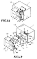
- Figures 1 to 4 show an example configuration of the ink-jet cartridge as the first embodiment of this invention.
- Figures 1A and 1B are an overall perspective view and an exploded perspective view, respectively,
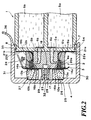
- Figure 2 is a partial cross section, and
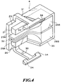
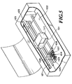
- Figure 3 and Figure 4 are perspective views of parts of Figure 1.
- IJC represents an entire ink-jet cartridge removably mountable on a printer body described later with reference to Figure 5.
- the ink-jet cartridge includes a tank portion 1, a print head portion 2, a protective tape 3 as a removable sealing member, and a protective cap 4 as an ink ejection portion pressing member, these members being formed substantially vertically symmetrical.
- the tank portion 1, as shown in Figure 2, is divided into two chambers, each accommodating an absorbent body 5a or 5b made of a porous material such as sponge.
- One absorbent body (5a for example) is impregnated with an ink as a printing agent and the other absorbent body (5b) with a liquid (print performance improving liquid) to improve the print performance.
- the ink and the print performance improving liquid are supplied to the print head portion 2 through supply ports 6a, 6b provided in each chamber.
- the tank portion 1 is formed with grooves 7, 8 on its outer side near the print head.
- the print head portion 2 has a head chip 9a to eject the print ink and a head chip 9b to eject the print performance improving liquid.
- These head chips 9a, 9b have virtually similar constructions and, as shown in Figure 3, include electrothermal transducers 10a, 10b to generate thermal energy for ejecting the ink and the print performance improving liquid, substrates 12a, 12b formed with electrodes 11a, 11b and drive elements (not shown), and orifice-formed members (hereinafter referred to as orifice plates) 14a, 14b formed with a predetermined number of orifices 13a, 13b at predetermined pitches.
- the following three parts are integrally formed in a common top plate or block for the head chips 9a, 9b.
- the three parts are the orifice plates 14a, 14b; portions which have grooves communicating with the orifices and forming liquid passages 16a, 16b at portions corresponding to the electrothermal transducers 10a, 10b and which are joined to the substrates 12a, 12b; and supply tubes 15a, 15b to introduce the ink and the print performance improving liquid from the tank portion 1.
- this embodiment uses a top plate 17 that is integrally formed with the supply tubes for the print ink and the print performance improving liquid, the liquid passage forming grooves and the orifice plates.
- the orifices 13a, 13b are arranged virtually parallelly on the orifice plates 14a, 14b that are almost planar portions of the top plate 17 facing the print medium.
- the top plate 17 has a liquid reservoir groove 18 formed between the orifice plates 14a, 14b in a direction almost parallel to the direction in which the orifices 13a, 13b are arranged.
- the print head portion 2 is assembled by mounting, from both sides, the substrates 12a, 12b of the head chips 9a, 9b on the liquid passages 16a, 16b that are parallelly formed on both sides of the top plate 17, by fixing the substrates 12a, 12b with retainer springs 20a, 20b and by sealing them with sealing materials 19a, 19b.
- the head chips 9a, 9b are attached with flexible printed circuit boards 22a, 22b that have contacts 21a, 21b for electrical connection with the printer body.
- the tank portion 1 and the print head portion 2 have their interiors completely divided into two systems, one for the print ink and one for the print performance improving liquid.
- the constructions for these two systems are virtually equal except for the kinds of liquids used and stored.
- the protective tape 3 and the protective cap 4 protect the print head portion 2 and seal the print ink orifices 13a and the print performance improving liquid orifices 13b. They can be dismounted as shown in Figure 1B just before the ink-jet cartridge is mounted in the printer body.
- the protective tape 3 has a virtually oval opening 23 at almost the center, on both sides of which the protective tape 3 seals the print ink orifices 13a and the print performance improving liquid orifices 13b.
- the protective tape 3 is bonded with a tab 24 that facilitates the removal of the tape.
- the protective cap 4 as also shown in Figure 4, generally comprises a base member 25, two elastic bodies 26, 27, and two absorbent bodies 28, 29.
- the base member 25 is integrally formed with two arm portions 30, 31 opposing vertically to each other to wrap around the print head portion 2; a rib 32 extending on the inner side of the base member 25 in the orifice arrangement direction; and a wall 33 generally shaped like a letter U to enclose an end of the base member.
- the arm portions 30, 31 have claws 34, 35 projecting inwardly from the free end part thereof.
- a flange 36 At the terminal end of the arm portion 31 is formed a flange 36 to facilitate the removal of the cap.
- the two elastic bodies 26, 27 are substantially square columns longer than the range where the orifices 13a, 13b are arranged.
- the two absorbent bodies 28, 29 have symmetrical shapes, each having a liquid introducing portion 28A, 29A and a reservoir portion 28B, 29B.
- These two elastic bodies 26, 27 and two absorbent bodies 28, 29 are arranged on both sides of the rib 32 on the inner side of the base member 25. That is, arranged from bottom to top of the figure are the elastic body 26, the absorbent body 28, the rib 32, the absorbent body 29, and the elastic body 27, all secured to the base member 25.
- the elastic bodies 26, 27 and the absorbent bodies 28, 29 are kept out of contact and spaced a predetermined interval. The shapes and dimensions of these members are properly determined so as to be able to perform the following functions.
- the state in which the above ink-jet cartridge is attached with the protective tape 3 and the protective cap 4 is briefly explained.
- the protective cap 4 is mounted by engaging its claws 34, 35 with the grooves 7, 8.
- the elastic bodies 26, 27 and the absorbent bodies 28, 29 are clamped between the base member 25 and the print head portion 2 and elastically deformed.
- the elastic bodies 26, 27 presses the protective tape 3 against the orifice plates 14a, 14b thus sealing all the orifices 13a, 13b.
- the width of the opening 23 of the protective tape 3 is greater than the width of the liquid reservoir groove 18 of the top plate 17.
- the liquid introducing portions 28A, 29A of the absorbent bodies 28, 29 engage the boundary portion of the liquid reservoir groove 18 inside the opening 23.
- the reservoir portions 28B, 29B of the absorbent bodies 28, 29 are installed in a space that avoids the print head portion 2.
- the tab 24 of the protective tape 3 is situated in a space between the print head portion 2 and the arm portion 31 of the protective cap 4.
- the performances required of at least one of the elastic bodies 26, 27 are that their compression residual strains are small, that they do not degrade or contaminate the constituent material of the print head portion 2, the pint ink and the print performance improving liquid, that they are not degraded or contaminated by these, and that because they close the fine orifices, their pressing surfaces need to be smooth. If a simple porous body is used, a sufficient pressing state may not be obtained because of the presence of pores larger than the orifices in the pressing surface.
- at least one of the elastic bodies 26, 27 uses a high-density microurethane foam (for example, Polon LE20 of Inoac Co. make) about 6 mm thick-a porous body having a smooth skin layer on the surface that meets the above requirements.
- the protective tape 3 may be formed of a flexible sheet about 10-40 ⁇ m thick, such as polyethylene terephthalate and, polypropylene, polytetrafluoroethylene, and an acrylic adhesive material about 10-40 ⁇ m thick.
- the print performance improving liquid is a liquid containing a compound that makes insoluble or aggregates colorants such as dyes or pigments in the ink, or makes insoluble and aggregates coloarants. In more concrete terms, a water solution of cation-based polymer is used.
- a common ink containing acid dye is used for the print ink. It is noted that this invention is not limited to the above examples as long as the constructions and materials do not deviate from the scope of this invention.
- the orifices are closed by the protective tape 3 which is kept attached (during transport, storage and marketing) until the cartridge begins to be used, preventing leakage of the ink and the print performance improving liquid.
- the liquid seeping gradually toward the other orifice group by capillary action generated at the joint portion between the protective tape 3 and the orifice plate surface can be blocked by the opening 23 formed in the protective tape 3 that nullifies the capillary action.
- the elastic bodies 26, 27 provided in the protective cap 4 that press against the orifices prevent leakage of the ink and the print performance improving liquid. If at least one of the liquids should leak, the liquid seeping toward the other orifice group by capillary action generated between the elastic body and the orifice plate surface (including capillary action generated at the contact surface of the protective tape 3 when the protective tape 3 is interposed as in this embodiment) can be blocked by forming independent pressing surfaces of the elastic bodies at each orifice group to cut off the capillary action.
- the rib 32, the absorbent bodies 28, 29 and the liquid reservoir groove 18 are arranged between these elastic bodies, the liquid seeping toward the other group of orifices can be stopped by the reservoir or by the extension of the surface distance that the seeping liquid must travel before it can reach the other orifice group.
- Figure 5 shows an outline configuration of the printer body that mounts the ink-jet cartridge described above.
- the contacts 21a, 21b of the ink-jet cartridge IJC come into contact with contacts (not shown) at predetermined positions on the carriage 101 and the ink-jet cartridge IJC now can receive drive signals from the printer body.
- the ink-jet cartridge IJC is moved along guide rails 123 in lateral directions (directions different from the orifice arrangement direction; for example, directions perpendicular to the orifice arrangement direction) together with the carriage 101 secured to a belt 121 connected to a drive source (not shown) by the driving action of the drive source. While being moved, the ink-jet cartridge IJC ejects the print ink and the print performance improving liquid from the orifices 13a, 13b in response to the drive signals received.
- both of the liquids are brought into contact with each other on the print medium 102 to form print dots and improve the print performance as by imparting water resistance to the dyes in the ink. That is, when the dyes in the ink react with the print performance improving liquid on the print medium 102, they instantly become insoluble and/or aggregate. Not only does this improve the water resistance but it also prevents undesired bleeding between different tones when inks of different tones (including shades) are used.
- the improvement of print performance mentioned here includes improvements of at least one of elements that are desired in improving the quality, reproducibility and preservability of an image formed, such as improvements in terms of three elements of color-brightness, chroma and tint-and improvements in reflection density, sharpness of edges, shape of dot, fixation of ink, water resistance and light resistance.
- the recovery means has caps 103, 104 made of elastic member such as rubber and suction pumps 105, 106.
- the cap 103 and the suction pump 105 correspond to the group of orifices 13a and the cap 104 and the suction pump 106 corresponds to the group of orifices 13b.
- the two caps 103, 104 are arranged vertically movable in Figure 5.
- Figure 6 shows the recovery means as it performs the capping or recovery operation.
- the two caps 103, 104 are ready to move up from the retracted (lowered) position indicated by two-dot chain line.
- these caps 103, 104 are pressed against the areas of the orifices 13a, 13b of the ink-jet cartridge IJC, respectively. That is, in the capping action the caps 103, 104 surround with the elastic members the groups of the orifices 13a, 13b that are separated from each other by the liquid reservoir groove 18 formed in the top plate 17 of the ink-jet cartridge IJC and hermetically enclose the inner spaces.
- the orifices are kept from drying when the cartridge stands by during the print operation, thus preventing the ink and the print performance improving liquid from becoming viscous or solidifying around the orifices.
- the orifices are also protected from dust, eliminating abnormal ejection.
- the suction pumps 105, 106 are activated to apply a suction force to the capped spaces to draw out the ink and the print performance improving liquid from the orifices 13a, 13b (so-called recovery operation).
- the printer body is also provided with two wiping means which are parallelly arranged closer to the print area than the recovery means.
- the wiping means have blades 107, 108 made of elastic member such as rubber and their blade holders.
- the blade holders 107a, 108a are moved up and down by a blade raise/lower mechanism that is engageable with the carriage 101 and driven by the movement of the carriage 101.
- the blades 107, 108 can thus be set at a projected (raised) position where they wipe ink and foreign matters sticking to the orifice plate surface of the ink-jet cartridge IJC and at a retracted (lowered) position (or standby position) where the blades do not contact the orifice plate surface.
- the mechanism is divided so that the blade 107 and the blade 108 can be raised or lowered independently of each other.
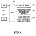
- Figure 9 shows an example configuration of a main part of the control system in the printer to perform appropriate wiping.
- Designated 501 is a CPU or main control unit to control various parts of the printer in performing print and recovery operations.
- Denoted 502 is a ROM that stores programs that correspond to various processing procedures executed by the CPU including the processing procedure of Figure 10.
- Reference number 503 represents a RAM that provides predetermined data area and work area.
- a carriage motor 505 causes the carriage 101 to scan.
- Raise/lower mechanisms 507 and 508 raise or lower the ink orifice blade 107 and the print performance improving liquid orifice blade 108.
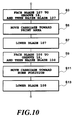
- Figure 10 shows one example of the procedure to execute wiping. This procedure can be started at a desired timing.
- the control is carried out to use the blade 107 in wiping the print ink orifice surface and the blade 108 in wiping the print performance improving liquid orifice surface.
- the blades 107, 108 are lowered to return to the standby position (step S7, S13). Performing the wiping in a direction away from the other group of orifices in this way can prevent liquid, if spattered by the snapping elastic blade, from adhering to the surface of the other group of orifices, which in turn prevents the mixing of the two liquids on the surface of the orifices.
- the print ink orifices and the print performance improving liquid orifices are provided with dedicated recovery caps (103 and 104) and dedicated blades (107 and 108) so that the two liquids can be independently handled.
- the two groups of orifices are also provided with independent dedicated suction pumps connected to the caps 103 and 104.
- This arrangement allows the ink and the print performance improving liquid-which aggregates the ink dyes and/or makes them insoluble-drawn out in the recovery operation to be handled properly and easily without the two liquids coming into contact with each other inside the caps 103, 104 and the suction pumps 105, 106. Further, during the wiping action of the blades this arrangement keeps the two liquids from mixing on the orifice surface. Thus, the ease of handling and reliability of the printer are improved.
- the two liquids should leak before use (during transport, storage or marketing) or if, after the cartridge has been installed in the printer, the liquid should adhere to the orifice surface as a result of the recovery or wiping action activated for some reason, the liquid seeping along the orifice surface toward the other group of orifices can be effectively blocked because the surface of the ink orifices and the surface of the print performance improving liquid orifices are not situated on the same continuous plane but are separated by the liquid reservoir groove.
- Figure 11 to Figure 13 represent other embodiments of the protective cap. These examples do not have the absorbent bodies 28, 29, the generally U-shaped wall of the protective cap enclosing the absorbent bodies, and the rib 32 arranged on the inner surface of the protective cap, all these employed in the first embodiment.
- the protective cap shown in Figure 11 has a groove 201 formed between and parallel to the two elastic bodies 26, 27. This construction increases the surface distance between the two elastic bodies 26, 27, as does the rib of the first embodiment, to block the leaking liquid that is seeping toward the other group of orifices.
- the protective cap of Figure 12 has a plurality of fine grooves 202 formed between and parallel to the two elastic bodies 26, 27.
- the liquid seeping toward the other group of orifices can be blocked by holding back the seeping liquid with the capillary action of the grooves, in the same way that the absorbent bodies of the first embodiment block the seeping liquid.
- the protective cap shown in Figure 13 has a liquid-repelling part 203 between the two elastic bodies 26, 27. This repels the liquid seeping toward the other group of orifices and limits the direction of liquid movement, thus blocking the advance of the seeping liquid.
- Selection of an appropriate treatment of making the surface liquid-repellent in this embodiment can be made according to the composition of the print ink and the print performance improving liquid.
- the preferred liquid repellent is a fluoropolymer with an average molecular weight of 2000 or higher and with water insolubility and organic solvent solubility.
- Examples of the preferred liquid repellent include compounds having one or more reactive groups-selected from among polyperfluoromethacrylate, polyperfluoroacrylate, fluoroalkyl group, fluoroallyl group, fluorocycloslkyl group, fluoroalkali and fluoroalkylallyl group-and a silazane group, or siloxane-based polymers synthesized by the condensation of alkoxysilane monomer.
- Such repellents can be applied to the surface of the protective cap typically by spraying or transfer method.
- the orifices are pressed by the elastic bodies 26, 27 of the protective cap 4, preventing leakage of the ink and the print performance improving liquid.
- the liquid seeping toward the other group of orifices by the capillary action generated between the elastic body and the orifice surface can be blocked by forming independent pressing surfaces of the elastic bodies at each orifice group to cut off the capillary action.
- the liquid reservoir groove 201, the finely roughed surface 202 or the liquid-repelling surface 203 is provided between the elastic bodies, the liquid seeping toward the other orifice group can be blocked by the reservoir or by the extension of the surface distance that the leaking liquid must travel before it can reach the other orifice group.
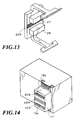
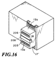
- Figure 14 to Figure 16 represent further embodiments of the print head.
- the print head portion shown in Figure 14 has a plurality of fine grooves 204 formed between and parallel to the rows of two orifice groups 13a, 13b formed in the top plate 17'. Should a liquid leakage occur, this construction can block the liquid seeping toward the other orifice group by holding back the seeping liquid with the capillary action of the grooves.
- the print head portion shown in Figure 15 has a liquid-repelling part 207, instead of the grooves 18, formed between the rows of the two groups of orifices 13a, 13b. This repels the liquid seeping toward the other group of orifices and limits the direction of liquid movement, thus blocking the advance of the seeping liquid.
- the liquid-repelling treatment used in this embodiment can be performed in the same way as the aforementioned protective cap.
- the print head portion shown in Figure 16 has an absorbent body 208 of a porous material embedded in the groove 18 formed between the rows of the two orifice groups 13a, 13b formed in the top plate 17'. This construction blocks the advancement of the liquid seeping toward the other orifice group by absorbing and holding the liquid.
- the liquid seeping along the orifice surface toward the other orifice group can be effectively blocked by the reservoir or by the extension of the surface distance that the leaking liquid must travel before it can reach the other orifice group, because the surface of the ink orifices and the surface of the print performance improving liquid orifices are not situated on the same continuous plane but are separated by the finely roughened surface 204, the liquid-repelling surface 207 or the absorbent member 208.
- the surfaces of the orifice plates of the top plate 17' in which the orifices 13a, 13b are formed is not limited to those of the first embodiment but may use other configurations such as shown in Figure 14 to 16, in which small steps (205, 206) are formed.
- the pressing state described above can be achieved by setting the height of the elastic body 27 larger than those of the other elastic bodies or by setting the hardness of the elastic body 27 higher than those of the other elastic bodies 26.
- the elastic body 27 that presses against the print performance improving liquid orifices can be formed of an acid-resistant material.
- the elastic bodies 26 are made of polyurethane elastomer porous material
- the elastic body 27 may use a silicone rubber foam with excellent acid resistance, instead of the polyurethane elastomer porous material.
- ribs 32 which heights are lower than those of the elastic bodies when elastically deformed, in order to prevent contact among the elastic bodies as may be caused by the deflection of the elastic bodies and to ensure that the elastic bodies can realize their appropriate pressing condition.
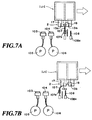
- the protective cap of the first embodiment is provided with holes 209, 210 that expose the absorbent bodies 28, 29-which soak the leaking liquid-to the outside of the cap and communicate the leaking liquid to the outside.
- a container 211 accommodating the ink-jet cartridge IJC during transport has ribs inside, by the side of which second absorbent bodies 212, 213 are formed. The ribs support the ink-jet cartridge IJC and also isolate the two absorbent bodies 212, 213 from each other.
- the two absorbent bodies 212, 213 are formed with the projected portions 212a, 213a that, when the ink-jet cartridge IJC is received in the container 211, fit into the holes 209, 210 of the protective cap to engage with the absorbent bodies 28, 29 of the protective cap.
- the ink-jet cartridge IJC and the transport container shown in Figure 17 With the ink-jet cartridge IJC and the transport container shown in Figure 17, the amount of liquid that can be retained in the absorbent bodies 28, 29 provided in the protective cap of the first embodiment can be compensated for. Hence, if a large amount of liquid should leak out, the arrangement inside the transport container 211 can prevent contact between the print ink and the print performance improving liquid that aggregates and/or makes insoluble the dyes in the inks and thereby enhance reliability.
- the present invention is not limited to the configurations of the above embodiments and any desired modifications may be made.
- the protective cap and/or the print head use one of the above configurations and, if this configuration can block the liquid advancement well, the protective tape 3 may not be formed with the opening 23.
- the present invention is applicable to a print head, an ink jet cartridge, an ink-jet recording (printing) apparatus which utilize electromechanical transducers and the like
- the present invention achieves distinct effect when applied to a recording head or a recording apparatus which has means for generating thermal energy such as electrothermal transducers or laser light, and which causes changes in ink by the thermal energy so as to eject ink. This is because such a system can achieve a high density and high resolution recording.
- the on-demand type apparatus has electrothermal transducers, each disposed on a sheet or liquid passage that retains liquid (ink), and operates as follows: first, one or more drive signals are applied to the electrothermal transducers to cause thermal energy corresponding to recording information; second, the thermal energy induces sudden temperature rise that exceeds the nucleate boiling so as to cause the film boiling on heating portions of the recording head; and third, bubbles are grown in the liquid (ink) corresponding to the drive signals. By using the growth and collapse of the bubbles, the ink is expelled from at least one of the ink ejection orifices of the head to form one or more ink drops.
- the drive signal in the form of a pulse is preferable because the growth and collapse of the bubbles can be achieved instantaneously and suitably by this form of drive signal.
- a drive signal in the form of a pulse those described in U.S. patent Nos. 4,463,359 and 4,345,262 are preferable.
- the rate of temperature rise of the heating portions described in U.S. patent No. 4,313,124 be adopted to achieve better recording.
- U.S. patent Nos. 4,558,333 and 4,459,600 disclose the following structure of a recording head, which is incorporated to the present invention: this structure includes heating portions disposed on bent portions in addition to a combination of the ejection orifices, liquid passages and the electrothermal transducers disclosed in the above patents. Moreover, the present invention can be applied to structures disclosed in Japanese Patent Application Laying-open Nos. 123670/1984 and 138461/1984 in order to achieve similar effects.
- the former discloses a structure in which a slit common to all the electrothermal transducers is used as ejection orifices of the electrothermal transducers, and the latter discloses a structure in which openings for absorbing pressure waves caused by thermal energy are formed corresponding to the ejection orifices.
- the present invention can be also applied to a so-called full-line type recording head whose length equals the maximum length across a recording medium.
- a recording head may consists of a plurality of recording heads combined together, or one integrally arranged recording head.
- the present invention can be applied to various serial type recording heads: a recording head fixed to the main assembly of a recording apparatus; a conveniently replaceable chip type recording head which, when loaded on the main assembly of a recording apparatus, is electrically connected to the main assembly, and is supplied with ink therefrom; and a cartridge type recording head integrally including an ink reservoir.
- a recovery system or a preliminary auxiliary system for a recording head as a constituent of the recording apparatus because they serve to make the effect of the present invention more reliable.
- the recovery system are a capping means and a cleaning means for the recording head, and a pressure or suction means for the recording head.
- the preliminary auxiliary system are a preliminary heating means utilizing electrothermal transducers or a combination of other heater elements and the electrothermal transducers, and a means for carrying out preliminary ejection of ink independently of the ejection for recording. These systems are effective for reliable recording.
- the number and type of recording heads to be mounted on a recording apparatus can be also changed. For example, only one recording head corresponding to a single color ink, or a plurality of recording heads corresponding to a plurality of inks different in color or concentration can be used.
- the present invention can be effectively applied to an apparatus having at least one of the monochromatic, multi-color and full-color modes.
- the monochromatic mode performs recording by using only one major color such as black.
- the multi-color mode carries out recording by using different color inks, and the full-color mode performs recording by color mixing.
- the processing liquid or solution for making ink dyestuff insoluble can be obtained in the following manner.
- ⁇ low molecular weight ingredients of cationic compound stearyl-trimethyl ammonium salts (tradename : Electrostriper QE, manufactured by Kao Corporation), or stearyl-trimethyl ammonium chloride (tradename : Yutamine 86P, manufactured by Kao Corporation) 2.0 parts by weight ⁇ high molecular weight ingredients of cationic compound; copolymer of diarylamine hydrochloride and sulfur dioxide (having an average molecular weight of 5000) (tradename : polyaminesulfon PAS-92, manufactured by Nitto Boseki Co., Ltd) 3.0 parts by weight ⁇ thiodiglycol; 10 parts by weight ⁇ water balance
- the resultant mixture is pressure-filtered with the use of a membrane filter of 0.22 ⁇ m in pore size (tradename : Fuloroporefilter, manufactured by Sumitomo Electric Industries, Ltd.) so that yellow ink Y1, magenta ink M1, cyan ink C1 and black ink K1 can be obtained.
- a membrane filter of 0.22 ⁇ m in pore size (tradename : Fuloroporefilter, manufactured by Sumitomo Electric Industries, Ltd.) so that yellow ink Y1, magenta ink M1, cyan ink C1 and black ink K1 can be obtained.
- the aforementioned processing liquid and ink are mixed with each other at the position on the printing medium or at the position where they penetrate in the printing medium.
- the ingredient having a low molecular weight or cationic oligomer among the cationic material contained in the processing liquid and the water soluble dye used in the ink having anionic radical are associated with each other by an ionic mutual function as a first stage of reaction whereby they are instantaneously separated from the solution liquid phase.
- the aggregated material formed by the ingredient having a low molecular weight or the cationic oligomer of the cationic material and the anionic dye by way of the aforementioned mechanism has increased viscosity.
- the aggregated material does not move as the liquid medium moves, ink dots adjacent to each other are formed by inks each having a different color at the time of forming a full colored image but they are not mixed with each other. Consequently, a malfunction such as bleeding does not occur.
- the aggregated material is substantially water-insoluble, water resistibility of a formed image is complete. In addition, light resistibility of the formed image can be improved by the shielding effect of polymer.
- insoluble or “aggregation” refers to observable events in only the above first stage or in both the first and second stages.
- Ink usable for carrying out the present invention should not be limited only to dyestuff ink, and pigment ink having pigment dispersed therein can also be used. Any type of processing liquid can be used, provided that pigment is aggregated with it.
- the following pigment ink can be noted as an example of pigment ink adapted to cause aggregation by mixing with the treatment liquid A1 previously discussed.
- yellow ink Y2, magenta ink M2, cyan ink C2 and black ink K2 each containing pigment and anionic compound can be obtained.
- the following materials are poured in a batch type vertical sand mill (manufactured by Aimex Co.), glass beads each having a diameter of 1 mm is filled as media using anion based high molecular weight material P-1 (aqueous solution containing a solid ingredient of styrene methacrylic acid ethylacrylate of 20 % having an acid value of 400 and average molecular weight of 6000, neutralizing agent : potassium hydroxide) as dispersing agent to conduct dispersion treatment for three hours while water-cooling the sand mill. After completion of dispersion, the resultant mixture has a viscosity of 9 cps and pH of 10.0.
- the dispersing liquid is poured in a centrifugal separator to remove coarse particles, and a carbon black dispersing element having a weight-average grain size of 10 nm is produced.
- the final product has a solid ingredient of about 10 %.
- Anionic high molecular P-2 (aqueous solution containing a solid ingredient of 20 % of stylen-acrlylic acid methyl methaacrylate having an acid value of 280 and an average molecular weight of 11,000, neutralizing agent : diethanolamine) is used as a dispersing agent and dispersive treatment is conducted in the same manner as production of the black ink K2 whereby yellow color dispersing element having a weight-average grain size of 103 nm is produced.
- ⁇ P-2 aqueous solution (having a solid ingredient of 20 %) 35 parts ⁇ C.
- I. pigment yellow 180 (tradename : Nobapalm yellow PH-G, manufactured by Hoechst Aktiengesellschaft) 24 parts ⁇ triethylen glycol 10 parts ⁇ diethylenglycol 10 parts ⁇ ethylene glycol monobutylether 1.0 parts ⁇ isopropyl alcohol 0.5 parts ⁇ water 135 parts
- the thus obtained yellow dispersing element is sufficiently dispersed in water to obtain yellow ink Y2 for ink jet printing and having pigment contained therein.
- the final product of ink contains a solid ingredient of about 10 %.
- Cyan colored-dispersant element having a weight-average grain size of 120 nm is produced by using the anionic high molecular P-1 used when producing the black ink K2 as dispersing agent, and moreover, using the following materials by conducting dispersing treatment in the same manner as the carbon black dispersing element.
- composition of cyan colored-dispersing element composition of cyan colored-dispersing element
- ⁇ P-1 aqueous solution (having solid ingredient of 20 %) 30 parts ⁇ C. I. pigment blue 153 (tradename : Fastogen blue FGF, manufactured by Dainippon Ink And Chemicals, Inc.) 24 parts ⁇ glycerin 15 parts ⁇ diethylenglycol monobutylether 0.5 parts ⁇ isopropyl alcohol 3 parts ⁇ water 135 parts
- the thus obtained cyan colored dispersing element is sufficiently stirred to obtain cyan ink C2 for ink jet printing and having pigment contained therein.
- the final product of ink has a solid ingredient of about 9.6 %.
- Magenta color dispersing element having a weight-average grain size of 115 nm is produced by using the anionic high molecular P-1 used when producing the black ink K2 as dispersing agent, and moreover, using the following materials in the same manner as that in the case of the carbon black dispersing agent.
- composition of the magenta colored dispersing element composition of the magenta colored dispersing element
- ⁇ P-1 aqueous solution (having a solid ingredient of 20 %) 20 parts ⁇ C. I. pigment red 122 (manufactured by Dainippon Ink And Chemicals, Inc.) 24 parts ⁇ glycerin 15 parts ⁇ isopropyl alcohol 3 parts ⁇ water 135 parts
- Magenta ink M2 for ink jet printing and having pigment contained therein is obtained by sufficiently dispersing the magenta colored dispersing element in water.
- the final product of ink has a solid ingredient of about 9.2 %.
- the kind of the printing medium is not specified in implementation of the present invention, and conventionally used plain paper, such as copy paper, bond paper and so forth can be suitably used.
- plain paper such as copy paper, bond paper and so forth
- a coated paper specially prepared for ink-jet printing, transparent film for OHP and so forth may also be used suitably.
- general wood free paper, glossy paper and so forth may also used suitably.
- the ink jet recording apparatus of the present invention can be employed not only as an image output terminal of an information processing device such as a computer, but also as an output device of a copying machine including a reader, and as an output device of a facsimile apparatus having a transmission and receiving function.
- this invention can prevent the dyes (coloring material) from becoming insoluble or aggregating at around the orifices, thus maintaining high image quality during use.
- the individual sealing surfaces of the protective tape (sealing member) and the individual pressing surfaces of the protective caps (orifice pressing members) for at least two groups of orifices are independent of each other, the ink-jet cartridge can be mounted to or dismounted from the printer with a single action, maintaining the high level of ease of handling.
- this invention prevents the ink and the print performance improving liquid from mixing should these liquids leak from the orifices during transport, storage or marketing, but the invention also prevents the both liquids from mixing at around the print head orifices and thereby prevents the dyes (coloring material) from becoming insoluble or aggregating when, after the cartridge is installed in the printer body, the liquids are spattered or the recovery and wiping operations are performed. This maintains high print quality during use.
- the storage method effectively prevents the mixing of the ink and the print performance improving liquid if one or both of these liquids should leak before the print head is mounted in the printer.
- the seal member (3) having an opening (23) and adapted to seal the first and second ejection portions (13a, 13b) so that its opening is located between these ejection portions is removably bonded to the print head (2). This arrangement closes the ejection portions with the protective tape (3), preventing leakage of the ink and the print performance improving liquid.
- the liquid seeping toward the other ejection portion by capillary action generated at the joint portion between the protective tape (3) and the orifice plate surface can be blocked by the opening (23) of the protective tape (3) that nullifies the capillary action.
Landscapes
- Ink Jet (AREA)
- Particle Formation And Scattering Control In Inkjet Printers (AREA)
Applications Claiming Priority (3)
| Application Number | Priority Date | Filing Date | Title |
|---|---|---|---|
| JP3068597 | 1997-02-14 | ||
| JP03068597A JP3768633B2 (ja) | 1997-02-14 | 1997-02-14 | インクジェットカートリッジおよびプリント装置 |
| JP30685/97 | 1997-02-14 |
Publications (3)
| Publication Number | Publication Date |
|---|---|
| EP0861732A2 true EP0861732A2 (de) | 1998-09-02 |
| EP0861732A3 EP0861732A3 (de) | 1999-12-01 |
| EP0861732B1 EP0861732B1 (de) | 2002-12-11 |
Family
ID=12310552
Family Applications (1)
| Application Number | Title | Priority Date | Filing Date |
|---|---|---|---|
| EP98102542A Expired - Lifetime EP0861732B1 (de) | 1997-02-14 | 1998-02-13 | Tintenstrahlkassette |
Country Status (4)
| Country | Link |
|---|---|
| US (1) | US6409325B1 (de) |
| EP (1) | EP0861732B1 (de) |
| JP (1) | JP3768633B2 (de) |
| DE (1) | DE69809979T2 (de) |
Cited By (11)
| Publication number | Priority date | Publication date | Assignee | Title |
|---|---|---|---|---|
| EP0997288A2 (de) * | 1998-10-27 | 2000-05-03 | Canon Kabushiki Kaisha | Tintensortiment, Tintenstrahlaufzeichnungsverfahren, Tintenstrahlaufzeichnungsgerät, und Verfahren zur Verminderung der Bildung fester Teilchen innerhalb der Reinigungseinheit |
| EP1332880A1 (de) * | 2002-01-31 | 2003-08-06 | Hewlett-Packard Company | Mundstückeinfassende Abdeckvorichtung für Tintenstrahldruckköpfe |
| EP1504911A1 (de) * | 2003-08-05 | 2005-02-09 | Hewlett-Packard Development Company, L.P. | Einwegtintenstrahlpatrone mit einer integrierten Düsenkappe |
| EP1466741A3 (de) * | 1998-05-13 | 2006-05-24 | Seiko Epson Corporation | Tintenpatrone für Tintenstrahlaufzeichnungsgerät |
| EP1721744A1 (de) * | 2005-05-10 | 2006-11-15 | BOWA Bosse + Wagner oHG | Vorrichtung zum dichten Transportieren und Aufbewahren einer auswechselbaren Patrone für einen Tintenstrahldrucker, sowie Verfahren zum Abdichten einer solchen Patrone |
| EP1525989A3 (de) * | 2003-10-22 | 2007-06-20 | Hewlett-Packard Development Company, L.P. | Anordnungen und Verfahren zum Drucken auf einem Substrat unter Verwendung von reaktiven Tinten |
| EP2039522A1 (de) * | 2008-02-28 | 2009-03-25 | Brother Kogyo Kabushiki Kaisha | Tintenpatronenbaugruppe |
| EP2184170A1 (de) * | 2008-11-07 | 2010-05-12 | Canon Kabushiki Kaisha | Flüssigkeitsausstoßvorrichtung, Flüssigkeitsausstoßkartusche und Vorrichtungsgehäusekappe |
| EP2233306A1 (de) * | 2008-01-15 | 2010-09-29 | Zhuhai Ninestar Management Co., Ltd. | Schutzvorrichtung für einen druckkopf-chip und kartusche mit der schutzvorrichtung |
| EP2930028A3 (de) * | 2014-04-07 | 2016-07-13 | Seiko Epson Corporation | Schutzelement für eine flüssigkeitsversorgungseinheit |
| US11305540B2 (en) * | 2018-07-20 | 2022-04-19 | Hewlett-Packard Development Company, L.P. | Cleaning print head cap |
Families Citing this family (24)
| Publication number | Priority date | Publication date | Assignee | Title |
|---|---|---|---|---|
| AUPQ439299A0 (en) | 1999-12-01 | 1999-12-23 | Silverbrook Research Pty Ltd | Interface system |
| JP3733266B2 (ja) | 1999-10-04 | 2006-01-11 | キヤノン株式会社 | 液体収納容器 |
| JP2001315346A (ja) * | 2000-03-02 | 2001-11-13 | Fuji Xerox Co Ltd | インク乾燥防止装置、それを備えたインクジェット記録ヘッド保管容器およびインクジェット記録装置、ならびにインク乾燥防止方法 |
| US6769761B2 (en) | 2002-08-29 | 2004-08-03 | Hewlett-Packard Development Company, L.P. | Inkjet printer having ink cartridge tape removal capability and method of assembling the printer |
| US7611222B2 (en) * | 2004-10-06 | 2009-11-03 | Hewlett-Packard Development Company, L.P. | Nozzle shield assembly |
| JP4715169B2 (ja) * | 2004-11-18 | 2011-07-06 | ブラザー工業株式会社 | インクカートリッジのための保護部材 |
| JP4731898B2 (ja) * | 2004-12-09 | 2011-07-27 | キヤノン株式会社 | インクタンク |
| JP4752297B2 (ja) * | 2005-03-10 | 2011-08-17 | ブラザー工業株式会社 | インクカートリッジ |
| US7360880B2 (en) | 2005-05-09 | 2008-04-22 | Silverbrook Research Pty Ltd | Ink cartridge having porous insert for use in a mobile device |
| US7284921B2 (en) | 2005-05-09 | 2007-10-23 | Silverbrook Research Pty Ltd | Mobile device with first and second optical pathways |
| JP4947257B2 (ja) * | 2005-10-13 | 2012-06-06 | ブラザー工業株式会社 | インクジェットヘッドの梱包構造 |
| US7452055B2 (en) * | 2005-12-05 | 2008-11-18 | Silverbrook Research Pty Ltd | Printing cartridge having self-referencing printhead |
| US7416290B2 (en) * | 2007-01-30 | 2008-08-26 | Brother Kogyo Kabushiki Kaisha | Ink cartridges |
| US8025378B2 (en) * | 2007-03-28 | 2011-09-27 | Brother Kogyo Kabushiki Kaisha | Ink cartridges |
| JP4803090B2 (ja) * | 2007-03-29 | 2011-10-26 | ブラザー工業株式会社 | 画像形成装置 |
| US8083321B2 (en) * | 2007-05-23 | 2011-12-27 | Lexmark International, Inc. | Removable radiation cured composition and process for protecting a micro-fluid ejection head |
| EP2127881B1 (de) * | 2008-05-29 | 2011-11-23 | Eastman Kodak Company | Wartungsstation für mehrfarbigen Druckkopf |
| JP5668918B2 (ja) * | 2010-11-18 | 2015-02-12 | セイコーエプソン株式会社 | 液体噴射装置及び液体噴射ヘッドのノズル形成面の払拭方法 |
| US20130286110A1 (en) * | 2012-04-30 | 2013-10-31 | Kevin J. O'Leary | Snap-on seal for inkjet ink tank |
| US8905528B2 (en) * | 2012-07-24 | 2014-12-09 | Eastman Kodak Company | Ink tank with a compliant wick |
| US9682567B2 (en) | 2014-10-21 | 2017-06-20 | Funai Electric Co., Ltd. | Print cartridge and an inkjet printer |
| US10384458B1 (en) | 2018-05-08 | 2019-08-20 | Funai Electric Co., Ltd. | Fluidic ejection cartridge for improved protective tape removal |
| US10814638B2 (en) | 2018-05-08 | 2020-10-27 | Funai Electric Co. Ltd | Fluidic ejection cartridge for improved protective tape removal |
| JP2023033944A (ja) * | 2021-08-30 | 2023-03-13 | コニカミノルタ株式会社 | インクジェット記録装置 |
Citations (7)
| Publication number | Priority date | Publication date | Assignee | Title |
|---|---|---|---|---|
| US4506277A (en) * | 1982-05-11 | 1985-03-19 | Canon Kabushiki Kaisha | Nozzle-restoring suction device for ink jet printer |
| US4599627A (en) * | 1983-09-08 | 1986-07-08 | Siemens Aktiengesellschaft | Apparatus and method for ink jet printer |
| EP0514632A2 (de) * | 1991-03-08 | 1992-11-25 | Canon Kabushiki Kaisha | Tintenstrahlaufzeichnungskopf und Schützverfahren dafür |
| EP0559206A2 (de) * | 1992-03-06 | 1993-09-08 | Canon Kabushiki Kaisha | Behälter für verbrauchbare Stoffe, sein Verpackungsmaterial und Verfahren zu seiner Sammlung |
| EP0671273A1 (de) * | 1994-03-10 | 1995-09-13 | Hewlett-Packard Company | Schutzkappe für einen Tintenstrahlschreiber |
| US5467118A (en) * | 1993-12-21 | 1995-11-14 | Hewlett-Packard Company | Ink cartridge for a hard copy printing or plotting apparatus |
| EP0741038A2 (de) * | 1995-04-27 | 1996-11-06 | Owens-Illinois Closure Inc. | Behältnis und Ausgabevorrichtung für Flüssigkeit |
Family Cites Families (26)
| Publication number | Priority date | Publication date | Assignee | Title |
|---|---|---|---|---|
| JPS5324486A (en) | 1976-08-12 | 1978-03-07 | Sanyo Chemical Ind Ltd | Post treating method of dyed ariicle |
| JPS5443733A (en) | 1977-09-13 | 1979-04-06 | Toyo Ink Mfg Co | Printing method |
| CA1127227A (en) | 1977-10-03 | 1982-07-06 | Ichiro Endo | Liquid jet recording process and apparatus therefor |
| US4330787A (en) | 1978-10-31 | 1982-05-18 | Canon Kabushiki Kaisha | Liquid jet recording device |
| US4345262A (en) | 1979-02-19 | 1982-08-17 | Canon Kabushiki Kaisha | Ink jet recording method |
| US4463359A (en) | 1979-04-02 | 1984-07-31 | Canon Kabushiki Kaisha | Droplet generating method and apparatus thereof |
| US4313124A (en) | 1979-05-18 | 1982-01-26 | Canon Kabushiki Kaisha | Liquid jet recording process and liquid jet recording head |
| JPS5684992A (en) | 1979-12-15 | 1981-07-10 | Ricoh Co Ltd | Ink jet recording method |
| US4558333A (en) | 1981-07-09 | 1985-12-10 | Canon Kabushiki Kaisha | Liquid jet recording head |
| JPS58128862A (ja) | 1982-01-26 | 1983-08-01 | Minolta Camera Co Ltd | インクジエツト記録方法 |
| JPS59123670A (ja) | 1982-12-28 | 1984-07-17 | Canon Inc | インクジエツトヘツド |
| JPS59138461A (ja) | 1983-01-28 | 1984-08-08 | Canon Inc | 液体噴射記録装置 |
| JPS6238155A (ja) | 1985-08-13 | 1987-02-19 | 松下電器産業株式会社 | 蓄熱装置 |
| JP2676699B2 (ja) | 1987-09-03 | 1997-11-17 | 株式会社リコー | インクジェット記録方法 |
| US5231416A (en) * | 1988-11-09 | 1993-07-27 | Canon Kabushiki Kaisha | Container for ink jet head and recovering method of ink jet head using container |
| US6097407A (en) * | 1988-11-09 | 2000-08-01 | Canon Kabushiki Kaisha | Package for ink jet head |
| AU635562B2 (en) * | 1989-09-18 | 1993-03-25 | Canon Kabushiki Kaisha | Recording head with cover |
| JPH04247954A (ja) * | 1991-01-18 | 1992-09-03 | Canon Inc | インクジェット記録ヘッド用キャップ,インクジェット記録ヘッド,およびインクジェット記録装置 |
| JP2952100B2 (ja) * | 1991-03-08 | 1999-09-20 | キヤノン株式会社 | インク収納部用封止部材及びそれを備えた記録ヘッド |
| EP0534634A1 (de) | 1991-09-23 | 1993-03-31 | Hewlett-Packard Company | Verfahren und Zusammensetzungen zur Herstellung von stabilen, wasserfesten bedrückten Bildern |
| JP3284352B2 (ja) * | 1993-05-25 | 2002-05-20 | キヤノン株式会社 | インクジェット記録ヘッドの収納容器 |
| US5424768A (en) * | 1993-06-21 | 1995-06-13 | Xerox Corporation | Zero-volume maintenance cap for an ink jet printhead |
| JPH0958009A (ja) * | 1995-08-23 | 1997-03-04 | Seiko Epson Corp | インクカートリッジ及びその梱包ケース及び梱包方法 |
| US5917525A (en) * | 1995-10-30 | 1999-06-29 | Pelikan Produktions Ag | Ink cartridge for a print head of an ink-jet printer |
| JPH111046A (ja) * | 1997-06-12 | 1999-01-06 | Brother Ind Ltd | 記録ヘッドユニットの梱包体及び記録ヘッドユニットの梱包方法 |
| JP3912568B2 (ja) * | 1997-11-07 | 2007-05-09 | ブラザー工業株式会社 | 印字装置 |
-
1997
- 1997-02-14 JP JP03068597A patent/JP3768633B2/ja not_active Expired - Fee Related
-
1998
- 1998-02-12 US US09/022,551 patent/US6409325B1/en not_active Expired - Fee Related
- 1998-02-13 DE DE69809979T patent/DE69809979T2/de not_active Expired - Lifetime
- 1998-02-13 EP EP98102542A patent/EP0861732B1/de not_active Expired - Lifetime
Patent Citations (7)
| Publication number | Priority date | Publication date | Assignee | Title |
|---|---|---|---|---|
| US4506277A (en) * | 1982-05-11 | 1985-03-19 | Canon Kabushiki Kaisha | Nozzle-restoring suction device for ink jet printer |
| US4599627A (en) * | 1983-09-08 | 1986-07-08 | Siemens Aktiengesellschaft | Apparatus and method for ink jet printer |
| EP0514632A2 (de) * | 1991-03-08 | 1992-11-25 | Canon Kabushiki Kaisha | Tintenstrahlaufzeichnungskopf und Schützverfahren dafür |
| EP0559206A2 (de) * | 1992-03-06 | 1993-09-08 | Canon Kabushiki Kaisha | Behälter für verbrauchbare Stoffe, sein Verpackungsmaterial und Verfahren zu seiner Sammlung |
| US5467118A (en) * | 1993-12-21 | 1995-11-14 | Hewlett-Packard Company | Ink cartridge for a hard copy printing or plotting apparatus |
| EP0671273A1 (de) * | 1994-03-10 | 1995-09-13 | Hewlett-Packard Company | Schutzkappe für einen Tintenstrahlschreiber |
| EP0741038A2 (de) * | 1995-04-27 | 1996-11-06 | Owens-Illinois Closure Inc. | Behältnis und Ausgabevorrichtung für Flüssigkeit |
Cited By (19)
| Publication number | Priority date | Publication date | Assignee | Title |
|---|---|---|---|---|
| EP1466741A3 (de) * | 1998-05-13 | 2006-05-24 | Seiko Epson Corporation | Tintenpatrone für Tintenstrahlaufzeichnungsgerät |
| EP0997288A2 (de) * | 1998-10-27 | 2000-05-03 | Canon Kabushiki Kaisha | Tintensortiment, Tintenstrahlaufzeichnungsverfahren, Tintenstrahlaufzeichnungsgerät, und Verfahren zur Verminderung der Bildung fester Teilchen innerhalb der Reinigungseinheit |
| EP0997288A3 (de) * | 1998-10-27 | 2000-07-26 | Canon Kabushiki Kaisha | Tintensortiment, Tintenstrahlaufzeichnungsverfahren, Tintenstrahlaufzeichnungsgerät, und Verfahren zur Verminderung der Bildung fester Teilchen innerhalb der Reinigungseinheit |
| US6425662B1 (en) | 1998-10-27 | 2002-07-30 | Canon Kabushiki Kaisha | Ink set, ink-jet recording process, ink-jet recording apparatus, and method for alleviating formation of solid within common recovery-system unit |
| EP1332880A1 (de) * | 2002-01-31 | 2003-08-06 | Hewlett-Packard Company | Mundstückeinfassende Abdeckvorichtung für Tintenstrahldruckköpfe |
| EP1504911A1 (de) * | 2003-08-05 | 2005-02-09 | Hewlett-Packard Development Company, L.P. | Einwegtintenstrahlpatrone mit einer integrierten Düsenkappe |
| US7029091B2 (en) | 2003-08-05 | 2006-04-18 | Hewlett-Packard Development Company, L.P. | Inkjet consumable cartridge with integrated nozzle cap |
| EP1525989A3 (de) * | 2003-10-22 | 2007-06-20 | Hewlett-Packard Development Company, L.P. | Anordnungen und Verfahren zum Drucken auf einem Substrat unter Verwendung von reaktiven Tinten |
| EP1721744A1 (de) * | 2005-05-10 | 2006-11-15 | BOWA Bosse + Wagner oHG | Vorrichtung zum dichten Transportieren und Aufbewahren einer auswechselbaren Patrone für einen Tintenstrahldrucker, sowie Verfahren zum Abdichten einer solchen Patrone |
| EP2233306A1 (de) * | 2008-01-15 | 2010-09-29 | Zhuhai Ninestar Management Co., Ltd. | Schutzvorrichtung für einen druckkopf-chip und kartusche mit der schutzvorrichtung |
| EP2233306A4 (de) * | 2008-01-15 | 2011-01-05 | Zhuhai Ninestar Man Co Ltd | Schutzvorrichtung für einen druckkopf-chip und kartusche mit der schutzvorrichtung |
| US8342665B2 (en) | 2008-01-15 | 2013-01-01 | Zhuhai Ninestar Management Co., Ltd. | Protector for print head chip and ink cartridge used by the same |
| CN101486272B (zh) * | 2008-01-15 | 2013-01-30 | 珠海纳思达电子科技有限公司 | 打印头芯片保护器及其墨盒与控制方法 |
| EP2039522A1 (de) * | 2008-02-28 | 2009-03-25 | Brother Kogyo Kabushiki Kaisha | Tintenpatronenbaugruppe |
| EP2184170A1 (de) * | 2008-11-07 | 2010-05-12 | Canon Kabushiki Kaisha | Flüssigkeitsausstoßvorrichtung, Flüssigkeitsausstoßkartusche und Vorrichtungsgehäusekappe |
| US8662361B2 (en) | 2008-11-07 | 2014-03-04 | Canon Kabushiki Kaisha | Liquid discharging device, liquid discharging cartridge, and device body cap |
| EP2930028A3 (de) * | 2014-04-07 | 2016-07-13 | Seiko Epson Corporation | Schutzelement für eine flüssigkeitsversorgungseinheit |
| US9475301B2 (en) | 2014-04-07 | 2016-10-25 | Seiko Epson Corporation | Protection member for liquid supply unit |
| US11305540B2 (en) * | 2018-07-20 | 2022-04-19 | Hewlett-Packard Development Company, L.P. | Cleaning print head cap |
Also Published As
| Publication number | Publication date |
|---|---|
| DE69809979D1 (de) | 2003-01-23 |
| US20020071014A1 (en) | 2002-06-13 |
| EP0861732B1 (de) | 2002-12-11 |
| EP0861732A3 (de) | 1999-12-01 |
| US6409325B1 (en) | 2002-06-25 |
| DE69809979T2 (de) | 2003-07-17 |
| JPH10226092A (ja) | 1998-08-25 |
| JP3768633B2 (ja) | 2006-04-19 |
Similar Documents
| Publication | Publication Date | Title |
|---|---|---|
| EP0861732B1 (de) | Tintenstrahlkassette | |
| JP3177128B2 (ja) | 吐出部、吐出部を用いたインクジェットカートリッジ、インクジェットプリント装置および方法 | |
| EP0790129B1 (de) | Flüssigkeitsausstossapparat, Kopfeinheit und Tintenstrahlkassette | |
| US20030117453A1 (en) | Inkjet recording method, inkjet recording apparatus, program and storage medium storing program code readable by computer | |
| US6231156B1 (en) | Ink-jet printing apparatus and ejection recovery method of printing head | |
| EP0699533B1 (de) | Tintenstrahlaufzeichnungsgerät und Verfahren | |
| JPH06191143A (ja) | インクジェット記録方法、かかる方法に用いるインクセット、かかる方法に用いる機器 | |
| JP3667096B2 (ja) | インクジェット記録装置及びインクジェット記録方法 | |
| JP3554099B2 (ja) | インクジェットプリント装置 | |
| EP0887184A2 (de) | Tintenstrahldruckverfahren und Apparat zum Durchführen des Druckens durch Verwenden von Tinte und einer Behandlungsflüssigkeit welche die Tinte unlöslich macht | |
| JP5699696B2 (ja) | 液体吐出ヘッド及び画像形成装置 | |
| JP2002154195A (ja) | インクジェットプリント装置 | |
| US6312117B1 (en) | Ink jet printer pen with extra fluid dispenser | |
| JPH10226090A (ja) | 記録装置 | |
| EP0858900A2 (de) | Tintenstrahldruckgerät und Tintenstrahldruckverfahren | |
| JP2004345290A (ja) | インクジェット記録装置、記録ヘッドの回復処理装置、および記録ヘッドの回復処理方法 | |
| EP0858896B1 (de) | Tintenstrahldruckgerät und dieses verwendende Druckverfahren | |
| JPH10128959A (ja) | 記録装置 | |
| JPH10128963A (ja) | インクジェット記録装置並びにその使用法 | |
| JP3168136B2 (ja) | インクタンクおよびインクジェットカートリッジおよびそれを用いたインクジェットプリント装置 | |
| JP3374886B2 (ja) | インクジェット記録ヘッド用キャッピング装置 | |
| JPH10230627A (ja) | インクジェット記録装置およびテストパターン作成方法 | |
| JP3667097B2 (ja) | インクジェット記録方法およびインクジェット記録装置 | |
| JP2860685B2 (ja) | インクジェット記録装置の回復方法 | |
| JPH10146991A (ja) | インクジェットプリント装置 |
Legal Events
| Date | Code | Title | Description |
|---|---|---|---|
| PUAI | Public reference made under article 153(3) epc to a published international application that has entered the european phase |
Free format text: ORIGINAL CODE: 0009012 |
|
| AK | Designated contracting states |
Kind code of ref document: A2 Designated state(s): CH DE ES FR GB IT LI NL |
|
| AX | Request for extension of the european patent |
Free format text: AL;LT;LV;MK;RO;SI |
|
| PUAL | Search report despatched |
Free format text: ORIGINAL CODE: 0009013 |
|
| AK | Designated contracting states |
Kind code of ref document: A3 Designated state(s): AT BE CH DE DK ES FI FR GB GR IE IT LI LU MC NL PT SE |
|
| AX | Request for extension of the european patent |
Free format text: AL;LT;LV;MK;RO;SI |
|
| RIC1 | Information provided on ipc code assigned before grant |
Free format text: 6B 41J 2/175 A, 6B 41J 2/21 B |
|
| 17P | Request for examination filed |
Effective date: 20000417 |
|
| AKX | Designation fees paid |
Free format text: CH DE ES FR GB IT LI NL |
|
| 17Q | First examination report despatched |
Effective date: 20001102 |
|
| GRAG | Despatch of communication of intention to grant |
Free format text: ORIGINAL CODE: EPIDOS AGRA |
|
| RTI1 | Title (correction) |
Free format text: INK-JET CARTRIDGE |
|
| RTI1 | Title (correction) |
Free format text: INK-JET CARTRIDGE |
|
| GRAG | Despatch of communication of intention to grant |
Free format text: ORIGINAL CODE: EPIDOS AGRA |
|
| GRAH | Despatch of communication of intention to grant a patent |
Free format text: ORIGINAL CODE: EPIDOS IGRA |
|
| GRAH | Despatch of communication of intention to grant a patent |
Free format text: ORIGINAL CODE: EPIDOS IGRA |
|
| GRAA | (expected) grant |
Free format text: ORIGINAL CODE: 0009210 |
|
| AK | Designated contracting states |
Kind code of ref document: B1 Designated state(s): CH DE ES FR GB IT LI NL |
|
| PG25 | Lapsed in a contracting state [announced via postgrant information from national office to epo] |
Ref country code: NL Free format text: LAPSE BECAUSE OF FAILURE TO SUBMIT A TRANSLATION OF THE DESCRIPTION OR TO PAY THE FEE WITHIN THE PRESCRIBED TIME-LIMIT Effective date: 20021211 Ref country code: LI Free format text: LAPSE BECAUSE OF FAILURE TO SUBMIT A TRANSLATION OF THE DESCRIPTION OR TO PAY THE FEE WITHIN THE PRESCRIBED TIME-LIMIT Effective date: 20021211 Ref country code: CH Free format text: LAPSE BECAUSE OF FAILURE TO SUBMIT A TRANSLATION OF THE DESCRIPTION OR TO PAY THE FEE WITHIN THE PRESCRIBED TIME-LIMIT Effective date: 20021211 |
|
| REG | Reference to a national code |
Ref country code: GB Ref legal event code: FG4D |
|
| REG | Reference to a national code |
Ref country code: CH Ref legal event code: EP |
|
| REF | Corresponds to: |
Ref document number: 69809979 Country of ref document: DE Date of ref document: 20030123 |
|
| NLV1 | Nl: lapsed or annulled due to failure to fulfill the requirements of art. 29p and 29m of the patents act | ||
| ET | Fr: translation filed | ||
| PG25 | Lapsed in a contracting state [announced via postgrant information from national office to epo] |
Ref country code: ES Free format text: LAPSE BECAUSE OF FAILURE TO SUBMIT A TRANSLATION OF THE DESCRIPTION OR TO PAY THE FEE WITHIN THE PRESCRIBED TIME-LIMIT Effective date: 20030627 |
|
| REG | Reference to a national code |
Ref country code: CH Ref legal event code: PL |
|
| PLBE | No opposition filed within time limit |
Free format text: ORIGINAL CODE: 0009261 |
|
| STAA | Information on the status of an ep patent application or granted ep patent |
Free format text: STATUS: NO OPPOSITION FILED WITHIN TIME LIMIT |
|
| 26N | No opposition filed |
Effective date: 20030912 |
|
| REG | Reference to a national code |
Ref country code: FR Ref legal event code: ST Effective date: 20061031 |
|
| REG | Reference to a national code |
Ref country code: FR Ref legal event code: D3 |
|
| PGFP | Annual fee paid to national office [announced via postgrant information from national office to epo] |
Ref country code: IT Payment date: 20120209 Year of fee payment: 15 |
|
| PGFP | Annual fee paid to national office [announced via postgrant information from national office to epo] |
Ref country code: FR Payment date: 20130315 Year of fee payment: 16 Ref country code: GB Payment date: 20130220 Year of fee payment: 16 Ref country code: DE Payment date: 20130228 Year of fee payment: 16 |
|
| REG | Reference to a national code |
Ref country code: DE Ref legal event code: R119 Ref document number: 69809979 Country of ref document: DE |
|
| GBPC | Gb: european patent ceased through non-payment of renewal fee |
Effective date: 20140213 |
|
| REG | Reference to a national code |
Ref country code: FR Ref legal event code: ST Effective date: 20141031 |
|
| REG | Reference to a national code |
Ref country code: DE Ref legal event code: R119 Ref document number: 69809979 Country of ref document: DE Effective date: 20140902 |
|
| PG25 | Lapsed in a contracting state [announced via postgrant information from national office to epo] |
Ref country code: DE Free format text: LAPSE BECAUSE OF NON-PAYMENT OF DUE FEES Effective date: 20140902 Ref country code: FR Free format text: LAPSE BECAUSE OF NON-PAYMENT OF DUE FEES Effective date: 20140228 Ref country code: GB Free format text: LAPSE BECAUSE OF NON-PAYMENT OF DUE FEES Effective date: 20140213 |
|
| PG25 | Lapsed in a contracting state [announced via postgrant information from national office to epo] |
Ref country code: IT Free format text: LAPSE BECAUSE OF NON-PAYMENT OF DUE FEES Effective date: 20140213 |