EP0861124B1 - Anordnung zum abtrennen von nichtmagnetisierbaren metallen aus einer feststoffmischung - Google Patents
Anordnung zum abtrennen von nichtmagnetisierbaren metallen aus einer feststoffmischung Download PDFInfo
- Publication number
- EP0861124B1 EP0861124B1 EP96917339A EP96917339A EP0861124B1 EP 0861124 B1 EP0861124 B1 EP 0861124B1 EP 96917339 A EP96917339 A EP 96917339A EP 96917339 A EP96917339 A EP 96917339A EP 0861124 B1 EP0861124 B1 EP 0861124B1
- Authority
- EP
- European Patent Office
- Prior art keywords
- fact
- conveyor belt
- magnetic rotor
- separating
- solids mixture
- Prior art date
- Legal status (The legal status is an assumption and is not a legal conclusion. Google has not performed a legal analysis and makes no representation as to the accuracy of the status listed.)
- Expired - Lifetime
Links
- 239000000203 mixture Substances 0.000 title claims abstract description 23
- 239000002184 metal Substances 0.000 title claims abstract description 13
- 229910052751 metal Inorganic materials 0.000 title claims abstract description 13
- 150000002739 metals Chemical class 0.000 title claims abstract description 5
- 239000007787 solid Substances 0.000 title claims abstract 16
- 238000000926 separation method Methods 0.000 claims abstract description 11
- 239000000463 material Substances 0.000 claims description 21
- 239000000470 constituent Substances 0.000 claims description 9
- 230000005415 magnetization Effects 0.000 claims description 3
- 230000001133 acceleration Effects 0.000 claims description 2
- 230000001846 repelling effect Effects 0.000 claims description 2
- 230000010355 oscillation Effects 0.000 claims 2
- QJVKUMXDEUEQLH-UHFFFAOYSA-N [B].[Fe].[Nd] Chemical compound [B].[Fe].[Nd] QJVKUMXDEUEQLH-UHFFFAOYSA-N 0.000 claims 1
- 229910045601 alloy Inorganic materials 0.000 claims 1
- 239000000956 alloy Substances 0.000 claims 1
- 230000009849 deactivation Effects 0.000 claims 1
- 230000004907 flux Effects 0.000 claims 1
- 229910001172 neodymium magnet Inorganic materials 0.000 claims 1
- 239000002245 particle Substances 0.000 claims 1
- 238000004804 winding Methods 0.000 claims 1
- 239000008247 solid mixture Substances 0.000 description 22
- 230000000694 effects Effects 0.000 description 14
- XEEYBQQBJWHFJM-UHFFFAOYSA-N Iron Chemical compound [Fe] XEEYBQQBJWHFJM-UHFFFAOYSA-N 0.000 description 7
- 239000010935 stainless steel Substances 0.000 description 6
- 229910001220 stainless steel Inorganic materials 0.000 description 6
- CWYNVVGOOAEACU-UHFFFAOYSA-N Fe2+ Chemical compound [Fe+2] CWYNVVGOOAEACU-UHFFFAOYSA-N 0.000 description 5
- 229910052755 nonmetal Inorganic materials 0.000 description 4
- 150000002843 nonmetals Chemical class 0.000 description 4
- -1 ferrous metals Chemical class 0.000 description 3
- 229910052742 iron Inorganic materials 0.000 description 3
- 238000010276 construction Methods 0.000 description 2
- 230000006978 adaptation Effects 0.000 description 1
- 230000002730 additional effect Effects 0.000 description 1
- 230000001914 calming effect Effects 0.000 description 1
- 239000007795 chemical reaction product Substances 0.000 description 1
- 239000012141 concentrate Substances 0.000 description 1
- 229910001234 light alloy Inorganic materials 0.000 description 1
Images

Classifications
-
- B—PERFORMING OPERATIONS; TRANSPORTING
- B03—SEPARATION OF SOLID MATERIALS USING LIQUIDS OR USING PNEUMATIC TABLES OR JIGS; MAGNETIC OR ELECTROSTATIC SEPARATION OF SOLID MATERIALS FROM SOLID MATERIALS OR FLUIDS; SEPARATION BY HIGH-VOLTAGE ELECTRIC FIELDS
- B03C—MAGNETIC OR ELECTROSTATIC SEPARATION OF SOLID MATERIALS FROM SOLID MATERIALS OR FLUIDS; SEPARATION BY HIGH-VOLTAGE ELECTRIC FIELDS
- B03C1/00—Magnetic separation
- B03C1/02—Magnetic separation acting directly on the substance being separated
- B03C1/23—Magnetic separation acting directly on the substance being separated with material carried by oscillating fields; with material carried by travelling fields, e.g. generated by stationary magnetic coils; Eddy-current separators, e.g. sliding ramp
- B03C1/24—Magnetic separation acting directly on the substance being separated with material carried by oscillating fields; with material carried by travelling fields, e.g. generated by stationary magnetic coils; Eddy-current separators, e.g. sliding ramp with material carried by travelling fields
- B03C1/247—Magnetic separation acting directly on the substance being separated with material carried by oscillating fields; with material carried by travelling fields, e.g. generated by stationary magnetic coils; Eddy-current separators, e.g. sliding ramp with material carried by travelling fields obtained by a rotating magnetic drum
-
- B—PERFORMING OPERATIONS; TRANSPORTING
- B03—SEPARATION OF SOLID MATERIALS USING LIQUIDS OR USING PNEUMATIC TABLES OR JIGS; MAGNETIC OR ELECTROSTATIC SEPARATION OF SOLID MATERIALS FROM SOLID MATERIALS OR FLUIDS; SEPARATION BY HIGH-VOLTAGE ELECTRIC FIELDS
- B03C—MAGNETIC OR ELECTROSTATIC SEPARATION OF SOLID MATERIALS FROM SOLID MATERIALS OR FLUIDS; SEPARATION BY HIGH-VOLTAGE ELECTRIC FIELDS
- B03C2201/00—Details of magnetic or electrostatic separation
- B03C2201/20—Magnetic separation of bulk or dry particles in mixtures
Definitions
- the invention relates to an arrangement for separating non-magnetizable Metals, especially non-ferrous metals from a solid mixture, essentially consisting of one with a deflecting the mixture components on throwing parabolas Alternating magnetic field generator, the at least two at a distance from each other arranged dividers are arranged downstream.
- Such an arrangement is in terms of the main components according to DE 38 17 003C1 and DE 42 00 093 A1 and is successful in practice applied. It has been found to be advantageous that a combination of the adjustable effective range of the alternating field generated by the magnetic rotor due to the position of the axis of rotation of the magnetic rotor in the quadrant of the material discharge zone according to DE 38 17 003 C1 with the effect according to DE 42 00 093 A1, namely from a solid mixture given to the alternating field generator in one pass several different components as fractions simultaneously to separate, an effective separation process for solid mixtures enables.
- the invention is therefore based on the object, an arrangement of the beginning described way to improve so that by a constructive link technical means, from the application area of the solid mixture to the other Conveying and discharge area up to the separation zones formed by the throwing parabolas their functional effects on increasing the quality of the separation result, i.e. Concentrate the purity of the individual material fractions.
- the arrangement basically consists of a solid mixture 1, which e.g. Iron / stainless steel (V2A), 1.1, non-metals / stainless steel (V4A), 1.2, non-ferrous metal mixture 1.3 and light metal mixture 1.4 contains, in the direction of the arrow, Usually inclined vibration channel 2, which is essential to the invention with a additional inclination 2.1 is provided, a conveyor belt 3 and others. with the in a head drum 3.3 eccentrically mounted magnetic rotor 3.4 as a non-ferrous cutting station and finally a separation crest station 4 for the individual fractions 1.1, 1.2, 1.3, 1.4.
- a solid mixture 1 which e.g. Iron / stainless steel (V2A), 1.1, non-metals / stainless steel (V4A), 1.2, non-ferrous metal mixture 1.3 and light metal mixture 1.4 contains, in the direction of the arrow, Usually inclined vibration channel 2, which is essential to the invention with a additional inclination 2.1 is provided, a conveyor belt 3 and others. with
- a drive drum 3.1 drives an endless conveyor belt 3.2 over the head drum 3.3, in which the eccentrically mounted and at least in the range ⁇ var (Fig. 2) the material discharge zone for non-ferrous metals adjustable, driven magnetic rotor 3.4 is arranged.
- the separation crest station 4 is divided into an area for the in this example mentioned fractions to be separated, such as any iron / stainless steel (V2A) 1.1, in this case from the area of a material discharge zone 3.5 (FIG. 2), and Non-metals / stainless steel (V4A) 1.2 from material drop zone 3.6, non-ferrous metal mixed fraction 1.3 from the material drop zone 3.7 and light metal mixture 1.4 from the Material drop zone 3.8, the latter two particularly from the areas of the material drop zones 3.5 and 3.6 due to the effect of the ⁇ in the position range var adjustable magnetic rotor 3.4 from the head drum 3.3 in different Throwing parabolas are repelled.
- V2A iron / stainless steel
- V4A Non-metals / stainless steel
- a characteristic of the arrangement of dividing vertices 4.1, 4.2, 4.3 is that they in each case between adjacent throwing parabolas of the separated fractions 1.1, 1.2, 1.3 and 1.4 protrude and otherwise function as described in DE 42 00 093 A1.
- This arrangement has the following surprising overall effect:
- this area is designed as a dissolving and accelerating section, that is to say that the solid mixture 1 dissolves and accelerates to the conveyor belt 3.2 and is surprisingly evenly distributed and there everything is quickly put in a quiet position.
- the resulting additional effect for the design of the conveyor belt 3 can be used constructively even for the implementation of a short construction, since previously the solid mixture required a relatively long way on the conveyor belt 3.2 until the position was calmed when the solid mixture 1 was transferred by means of a single inclined vibrating trough 2 .
- This effect which is essential to the invention, is a decisive starting effect for influencing the separation quality for the function of the arrangement.
- This effect which has so far only been sought but not yet feasible, is having an effect the described calming on the one hand in the further functional sequence and on the other hand, in the construction of the conveyor belt 3 quasi double acting.
- the subsequent sequence namely by means of a speed control n, is thus also possible var of the magnet rotor 3.4 via a frequency converter, not shown, and by means of different magnetization times on the one to be separated Grain size and material properties of the parts of the solid mixture 1 over to act on a time-variable magnetic field structure, particularly advantageous influenced.
- the separation crest station 4 can thus with regard to the generation particularly pure fractions 1.1 to 1.4 can be used efficiently.
- the effects of the features according to further claims 2 support this to 7 the effects described above and ensure the advantageous overall effect with regard to the separate fractions 1.1 to 1.4.
- In the rest Claims 8 to 24 embodiments are described in addition to a safe Operating the arrangement continues to contribute to the quality of the separation result and thus the task according to the invention and the target Subordinate overall effect.
- the variety can with the invention the fractions to be separated from the solid mixtures described above can be further increased since the arrangement produced according to the invention the given solid mixtures as well as their different electro-physical Properties as well as their different geometric shapes and more heterogeneous material flows are taken into account for the quality of the end products.
Landscapes
- Sorting Of Articles (AREA)
- Manufacture And Refinement Of Metals (AREA)
- Attitude Control For Articles On Conveyors (AREA)
- Processing Of Solid Wastes (AREA)
Description
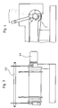
- Fig. 1
- die schematische Seitenansicht der erfindungsgemäßen Anordnung mit prinzipieller Funktionsdarstellung,
- Fig. 2
- die schematische Seitenansicht der Kopftrommel des Fördergurtes mit dem Wirkprinzip des exzentrisch gelagerten Magnetrotors,
- Fig. 3
- die Vorderansicht der Kopftrommel und
- Fig. 4
- die Seitenansicht nach Fig. 3.
Mittels der zusätzlichen Neigung 2.1 der Vibrationsrinne 2 im Bereich der Übergabe des Feststoffgemisches 1 auf den Fördergurt 3.2 ist dieser Bereich als Auflöse- und Beschleunigungsstrecke ausgebildet, d.h., daß das Feststoffgemisch 1 sich auflösend und beschleunigt dem Fördergurt 3.2 zugeführt und dort überraschend gleichmäßig verteilt und vor allen Dingen schnell in eine ruhige Lage versetzt wird. Der daraus für die Auslegung des Förderbandes 3 zusätzliche Effekt kann konstruktiv sogar noch für die Realisierung einer kurzen Bauweise ausgenutzt werden, da bisher bei einer Übergabe des Feststoffgemisches 1 mittels einfach geneigter Vibrationsrinne 2 das Feststoffgemisch einen relativ langen Weg auf dem Fördergurt 3.2 bis zur Lageberuhigung brauchte. Diese erfindungswesentliche Wirkung ist für die Funktion der Anordnung ein maßgebender Starteffekt zur Beeinflussung der Trennqualität.
- 1
- Feststoffgemisch
- 1.1
- Fraktion/Eisen Edelstahl (V2A)
- 1.2
- Fraktion Nichtmetalle/Edelstahl (V4A)
- 1.3
- Fraktion NE-Metall-Gemisch
- 1.4
- Fraktion Leichtmetallgemisch
- 2
- Vibrationsrinne
- 2.1
- zusätzliche Neigung
- 3
- Förderband
- 3.1
- Antriebstrommel
- 3.2
- Fördergurt
- 3.3
- Kopftrommel
- 3.4
- Magnetrotor
- 3.5
- Materialabwurfzone (für Fe)
- 3.6
- Materialabwurfzone (für Nichtmetalle/V4A)
- 3.7
- Materialabwurfzone (für NE-Mischfraktion)
- 3.8
- Materialabwurfzone (für NE-Leichtmetall)
- 3.9
- Magnete
- 3.10
- Parallelführungsgestänge
- 3.11
- Antriebsmotor für Magnetrotor 3.4
- 4
- Trennscheitelstation
- 4.1
- Trennscheitel
- 4.2
- Trennscheitel
- 4.3
- Trennscheitel
- v
- var Geschwindigkeitsregelung des Förderbandes 3
- F
- var variable Abstoßkraft
- α
- var verstellbare Position des Magnetrotors 3.4
- n
- var Drehzahlregelung des Magnetrotors 3.4
-
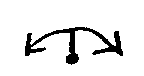
- schematische Darstellung der Ausrichtung eines Trennscheitels (4.1, 4.2 oder 4.3) durch Verschwenken um die Achse
-

- schematische Darstellung der Zustellung eines Trennscheitels (4.1, 4.2 oder 4.3) durch die horizontale Verstellung der Achse
-

- schematische Darstellung der Zustellung oder des Aufsteckens eines Trennscheitels (4.1, 4.2 oder 4.3) durch die vertikale Verstellung der Achse
Claims (23)
- Anordnung zum Abtrennen von nichtmagnetisierbaren Metallen aus einem Feststoffgemisch, bestehend aus einer die Feststoffmischung zuführenden Aufgabevorrichtung, einem die Feststoffmischung transportierenden endlosen Fördergurt (3.2) mit auf einem Rahmen gelagerten Gurttrommeln, von denen die am Abgabeende befindliche Kopftrommel (3.3) einen angetriebenen, exzentrisch gelagerten, verstellbaren Magnetrotor (3.4) aufweist, der die Bestandteile des Feststoffgemisches mittels Wechselmagnetfelderzeuger auf materialspezifisch unterschiedliche Wurfparabeln auslenkt, sowie einer der Kopftrommel (3.3) nachgeordneten Trennscheitelstation (4) mit Trennscheiteln (4.1, 4.2, 4.3) wobei der Magnetrotor (3.4) zur Anpassung an die jeweils zu trennende Korngröße und an die Materialbeschaffenheit des Feststoffgemisches mittels unterschiedlicher Magnetisierungszeiten über einen schnelleren oder langsameren Magnetfeldaufbau eine von einem Frequenzumrichter gesteuerte Drehzahlregelung (n var) besitzt und die Trennscheitel (4.1, 4.2, 4.3) jeweils zwischen benachbarte Wurfparabeln der getrennten Fraktionen (1.1, 1.2, 1.3, 1.4) angeordnet und einstellbar sind, dadurch gekennzeichnet, daßa) die als Vibrationsrinne (2) ausgebildete Aufgabevorrichtung im Bereich der Übergabe eine als zusätzliche Neigung (2.1) gestaltete Auflöse- und Beschleunigungsstrecke zur gleichmäßigen, lageberuhigten und fördergurtschonenden Verteilung des Feststoffgemisches (1) auf dem Fördergurt (3.2) aufweist,b) das Förderband (3) zur Anpassung des Verhältnisses Mengenstrom/Durchsatzleistung, Beeinflussung der Aufenthaltszeit des Feststoffgemisches (1) im Wirbelstromfeld des Magnetrotors (3.4) und Veränderung der Abwurfparabel des jeweiligen Bestandteils des Feststoffgemisches (1) Mittel für eine Geschwindigkeitsregelung (v var) enthält undc) der Magnetrotor (3.4) bezogen auf die Anpassung der Magnetkraft an den Abwurfpunkt des jeweiligen Bestandteils der Feststoffmischung (1) in einem Bereich (α var) von ≥ 90° so verstellbar und ausgebildet ist, daß eine variable Abstoßkraft (F var) für ein materialspezifisch weites Abstoßen des jeweiligen Bestandteils der Feststoffmischung (1) von der Kopftrommel (3.3) durch ein variables Wirbelstromfeld erzeugbar ist.
- Anordnung nach Anspruch 1, dadurch gekennzeichnet, daß die Kopftrommel (3.3) und der dieselbe umschlingende Fördergurt (3.2) zur Erreichung einer wirksameren Nähe des Magnetfeldes zu den Bestandteilen des Feststoffgemisches (1) und einer erhöhten Abstoßkraft (F var) relativ dünnwandig bzw. mit einer geringen Dicke ausgebildet sind.
- Anordnung nach Anspruch 2, dadurch gekennzeichnet, daß der Fördergurt (3.2) zwecks geringerer Belastung der dünnwandigen Kopftrommel (3.3) und zur wirksameren Nähe des Magnetfeldes zu den Bestandteilen des Feststoffgemisches (1) eine Dicke im Bereich von 1,7 bis 4 mm aufweist.
- Anordnung nach Anspruch 2, dadurch gekennzeichnet, daß die Kopftrommel (3.3) für eine wirksamere Nähe des Magnetfeldes zu den Bestandteilen des Feststoffgemisches (1) eine Mantelstärke von ca. 4 mm bei 1000 mm Arbeitsbreite besitzt und vorrangig aus GFK oder gleichartigem Material gefertigt ist.
- Anordnung nach Anspruch 1, dadurch gekennzeichnet, daß der Magnetrotor (3.4) zur Erhöhung der Polwechselfrequenz und der Abstoßkraft (F var) mit Feinpolen ausgerüstet ist.
- Anordnung nach Anspruch 5, dadurch gekennzeichnet, daß der Magnetrotor (3.4) mit Magneten (3.9) aus einer Neodym-Eisen-Bor-Legierung für ein starkes Wirbelstromfeld bestückt ist.
- Anordnung nach Anspruch 5, dadurch gekennzeichnet, daß der Magnetrotor (3.4) mit relativ kleinen Magneten (3.9) in Vielpolreihenanordnung zur Erhöhung des Polwechselbereiches von ca. 320 bzw. 480 auf ca. 1040 bzw. 1440 Hz und der Abstoßkraft (F var) gleicher Maximal-Drehzahl des Magnetrotors (3.4) von ca. 2400 bzw. 3600 min -1 ausgerüstet ist.
- Anordnung nach Anspruch 1, dadurch gekennzeichnet, daß zur Verstellung des Magnetrotors (3.4) und gleichmäßigen Belastung der Lager des Magnetrotors (3.4) ein Parallelführungsgestänge (3.10) vorgesehen ist.
- Anordnung nach Anspruch 1, dadurch gekennzeichnet, daß im Bereich der Lager des Magnetrotors (3.4) zur Feststellung unzulässiger Unwuchten eine Schwingungsüberwachung vorgesehen ist.
- Anordnung nach Anspruch 1, dadurch gekennzeichnet, daß zur Feststellung der Rotation der über den Fördergurt angetriebenen Kopftrommel (3.3) bzw. zur Anzeige einer Störung mittels lmpulsgeber von der Kopftrommel (3.3) eine Bandlaufüberwachung vorgesehen ist.
- Anordnung nach Anspruch 1, dadurch gekennzeichnet, daß unabhängig vom Frequenzumrichter mittels elektronischer Zweikanalsicherheitswächter eine Drehzahlüberwachung des Magnetrotors (3.4) zur Vermeidung überhöhter Drehzahlen, die ein Ablösen von Magneten (3.9) bewirken, vorgesehen ist.
- Anordnung nach Anspruch 1, dadurch gekennzeichnet, daß ein Antriebsmotor (3.11) für den Magnetrotor (3.4) eine automatisch betätigbare mechanische Bremse aufweist, die bei Spannungsausfall, Abschaltung der Anordnung, Not-Aus-Schaltung, Ansprechen der Schwingungsüberwachung, Ansprechen der Bandlaufüberwachung und/oder Ansprechen der Drehzahlüberwachung wirksam wird.
- Anordnung nach Anspruch 1, dadurch gekennzeichnet, daß die Trennscheitel (4.1, 4.2, 4.3) so einstellbar sind, daß zur Vermeidung des Abprallens von Teilen der getrennten Fraktionen (1.1, 1.2, 1.3, 1.4) die Trennflächen der Trennscheitel (4.1, 4.2, 4.3) mittlere Sehnen bzw. mittlere Tangenten zwischen den Wurfparabeln der Fraktionen (1.1, 1.2, 1.3, 1.4) bilden.
- Anordnung nach Anspruch 1 und 13, dadurch gekennzeichnet, daß kombinierte Mittel für eine Ausrichtung mindestens eines der Trennscheitel (4.1, 4.2 oder 4.3) durch Verschwenken um die Achse sowie eine Zustellung derselben in dem jeweiligen Trennbereich vorgesehen sind, wobei die Zustellung durch eine horizontale Verstellung der Achse und/oder die Zustellung oder auch ein Aufstecken als vertikale Verstellung der Achse erfolgen.
- Anordnung nach Anspruch 1, 13 und 14, gekennzeichnet durch auf einer Schaltkulisse wirkende kombinierte Mittel.
- Anordnung nach Anspruch 1, dadurch gekennzeichnet, daß auf dem Fördergurt (3.2) Mitnehmer zum Herausbefördern magnetischer Teile aus dem Magnetbereich vorgesehen sind.
- Anordnung nach Anspruch 1, dadurch gekennzeichnet, daß mit dem Untertrum des Fördergurtes (3.2) korrespondierende Abstreifer zur Säuberung des Fördergurtes (3.2) von anhaftenden Teilen vorgesehen sind.
- Anordnung nach Anspruch 1 und 17, dadurch gekennzeichnet, daß ein in Laufrichtung des Fördergurtes (3.2) gesehen erster Abstreifer den Fördergurt (3.2) streift und ein zweiter Abstreifer gegenüber dem Fördergurt (3.2) mit geringem Abstand angeordnet ist, wodurch zunächst anhaftende Teile bzw. Schmutz abgeschlagen und danach aufgefangen werden.
- Anordnung nach Anspruch 1, 13, 14 und/oder 15, dadurch gekennzeichnet, daß ein Trennscheitel (4.1) zur Abscheidung von anfallendem Fe und/oder ggf. Schmutz vorgesehen ist.
- Anordnung nach Anspruch 1, 13, 14, 15 und/oder 19, dadurch gekennzeichnet, daß der Trennscheitel (4.1) im Bereich (3.5, 3.6) einer möglichen Abwurfzone für Fe einstellbar ist.
- Anordnung nach Anspruch 1, 13, 14, 15, 19 und/oder 20, dadurch gekennzeichnet, daß der Trennscheitel (4.2) mit seiner Oberkante in der unter dem Einfluß der Wirbelströme des Magnetrotors (3.4) turbulenten Zone des Bereiches (3.6, 3.7) endet, in dem der Magnetrotor (3.4) die NE-Metalle des zu trennenden Feststoffgemisches (1) im Bereich (α var) abstößt.
- Anordnung nach Anspruch 1, 13, 14, 15, 19, 20 und/oder 21, dadurch gekennzeichnet, daß die Trennscheitel (4.1, 4.2, 4.3) aufsteckbar sind.
- Anordnung nach Anspruch 1, gekennzeichnet durch einen Rahmen für die Lagerung der Antriebstrommel (3.1) und Kopftrommel (3.3), der im Querschnitt eine zur Seite offene c-artige Bauweise zur De- und Montage eines Fördergurtes (3.2) ohne aufwendige Hilfsmittel aufweist.
Applications Claiming Priority (3)
| Application Number | Priority Date | Filing Date | Title |
|---|---|---|---|
| DE19521415A DE19521415C2 (de) | 1995-06-14 | 1995-06-14 | Anordnung zum Abtrennen von nichtmagnetisierbaren Metallen aus einem Feststoffgemisch |
| DE19521415 | 1995-06-14 | ||
| PCT/DE1996/001038 WO1997000138A1 (de) | 1995-06-14 | 1996-06-13 | Anordnung zum abtrennen von nichtmagnetisierbaren metallen aus einer feststoffmischung |
Publications (2)
| Publication Number | Publication Date |
|---|---|
| EP0861124A1 EP0861124A1 (de) | 1998-09-02 |
| EP0861124B1 true EP0861124B1 (de) | 2001-08-16 |
Family
ID=7764231
Family Applications (1)
| Application Number | Title | Priority Date | Filing Date |
|---|---|---|---|
| EP96917339A Expired - Lifetime EP0861124B1 (de) | 1995-06-14 | 1996-06-13 | Anordnung zum abtrennen von nichtmagnetisierbaren metallen aus einer feststoffmischung |
Country Status (5)
| Country | Link |
|---|---|
| US (1) | US6068133A (de) |
| EP (1) | EP0861124B1 (de) |
| AT (1) | ATE204210T1 (de) |
| DE (2) | DE19521415C2 (de) |
| WO (1) | WO1997000138A1 (de) |
Cited By (2)
| Publication number | Priority date | Publication date | Assignee | Title |
|---|---|---|---|---|
| CN105689119A (zh) * | 2016-03-24 | 2016-06-22 | 陈勇 | 一种传送带式超高磁场选磁铁矿装置 |
| WO2019097528A1 (en) * | 2017-11-16 | 2019-05-23 | Osmund Justin Jebaraj | Impact- screen |
Families Citing this family (32)
| Publication number | Priority date | Publication date | Assignee | Title |
|---|---|---|---|---|
| CN1354694A (zh) * | 1999-04-14 | 2002-06-19 | 艾克斯普技术公司 | 用于使用电力和磁力分类颗粒的方法和设备 |
| US6302275B1 (en) * | 2000-06-01 | 2001-10-16 | Erie E Magnetics | Belt tracking for magnetic roll separator |
| DE10057535C1 (de) | 2000-11-20 | 2002-08-22 | Steinert Gmbh Elektromagnetbau | Vorrichtung zum Abtrennen von nichtmagnetisierbaren Metallen und Fe-Anteilen aus einer Feststoffmischung |
| NL1025050C1 (nl) * | 2003-03-17 | 2004-09-21 | Univ Delft Tech | Werkwijze voor het winnen van non-ferrometaal-houdende deeltjes uit een deeltjesstroom. |
| NL1023651C2 (nl) * | 2003-06-12 | 2004-12-14 | Reukema Non Ferro Scheiding B | Afvalscheidingsinstallatie met sterzeef en wervelstroomscheider. |
| BRPI0418888A (pt) * | 2004-06-07 | 2007-11-20 | Sgm Gantry Spa | separador magnético, e, método para operar o mesmo |
| US7296687B2 (en) * | 2005-01-10 | 2007-11-20 | Outotec Oyj | Methods of separating feed materials using a magnetic roll separator |
| DE102005054811B4 (de) * | 2005-07-01 | 2007-06-14 | Steinert Elektromagnetbau Gmbh | Verfahren und Vorrichtung zum Abtrennen von Metallfraktionen und/oder -teilen aus Materialgemischen |
| US20080257795A1 (en) * | 2007-04-17 | 2008-10-23 | Eriez Manufacturing Co. | Multiple Zone and Multiple Materials Sorting |
| NL2001431C2 (nl) | 2008-04-02 | 2009-10-05 | Univ Delft Tech | Werkwijze voor het scheiden van een afvalstroom. |
| US7841474B2 (en) * | 2008-11-19 | 2010-11-30 | Outotec Oyj | Beltless rare earth roll magnetic separator system and method |
| CL2009001763A1 (es) * | 2009-08-21 | 2009-12-04 | Superazufre S A | Equipo separador del tipo rodillo magnetico para concentracion de minerales y materiales particulados, posee un alimentador de material, un rodillo tractor y un sistema separador de productos, donde el manto del rodillo esta cubierto por imanes dispuestos proximos entre si y con sus ejes magneticos en disposicion radial y polaridades aleatorias. |
| UA106632C2 (uk) * | 2009-09-07 | 2014-09-25 | Кертін Юніверсеті Оф Текноледжі | Спосіб сортування сипкої речовини |
| DE202009014381U1 (de) * | 2009-10-23 | 2010-12-09 | Imro Maschinenbau Gmbh | Vorrichtung zur Separation von Nichteisenmetallen |
| US8505734B1 (en) | 2009-12-02 | 2013-08-13 | David C. Wise | Apparatus for removing magnetic materials |
| ES2425338T3 (es) | 2010-07-28 | 2013-10-14 | Inashco R&D B.V. | Aparato de separación |
| IT1402570B1 (it) * | 2010-11-12 | 2013-09-13 | Sgm Gantry Spa | Cernitrice per materiali ferromagnetici con rullo magnetico eccentrico |
| NL2006306C2 (en) * | 2011-02-28 | 2012-08-29 | Inashco R & D B V | Eddy current seperation apparatus, separation module, separation method and method for adjusting an eddy current separation apparatus. |
| US9289778B2 (en) * | 2012-01-24 | 2016-03-22 | GM Global Technology Operations LLC | Magnetic separator system and method using spatially modulated magnetic fields |
| US8807344B2 (en) * | 2012-03-19 | 2014-08-19 | Mid-American Gunite, Inc. | Adjustable magnetic separator |
| BR102012008340B8 (pt) * | 2012-03-19 | 2022-12-13 | Steel Participacoes E Investimentos S A | Processo e sistema para recuperação a seco de finos e super finos de minério óxido de ferro |
| CN103495499B (zh) * | 2013-09-29 | 2016-08-24 | 佛山市高明彩乐福塑胶色料有限公司 | 一种磁性颗粒过滤机 |
| NL2013128B1 (nl) * | 2014-07-04 | 2016-09-09 | Goudsmit Magnetic Systems B V | Omleidrol voor een non-ferro afvalscheider, alsmede non-ferro afvalscheider voorzien van de omleidrol. |
| CN105223902A (zh) * | 2015-11-05 | 2016-01-06 | 张荣斌 | 一种矿山用盘式磁选机的自动控制系统及方法 |
| CN105689120A (zh) * | 2016-03-24 | 2016-06-22 | 陈勇 | 将磁铁矿拉离磁场的装置 |
| FR3058330B1 (fr) * | 2016-11-10 | 2019-01-25 | Alfyma Industrie | Dispositif optimise de separation de produits |
| US10751723B2 (en) * | 2017-04-26 | 2020-08-25 | Adr Technology B.V. | Method and apparatus for liberating particles from moist MSWI ash |
| CN109592376B (zh) * | 2018-11-06 | 2021-05-25 | 首钢集团有限公司 | 一种磁滚筒自动分料控制装置 |
| KR102024574B1 (ko) * | 2018-12-11 | 2019-11-14 | 한국선별기 주식회사 | 경사형 자력 선별기 |
| US11318476B2 (en) | 2020-04-30 | 2022-05-03 | Mss, Inc. | Separation of ferrous materials |
| US11465158B2 (en) | 2020-04-30 | 2022-10-11 | Mss, Inc. | Separation of ferrous materials |
| US12303942B1 (en) | 2024-09-06 | 2025-05-20 | Trinity Metals, LLC | System and method for mixed material magnesium sorting |
Family Cites Families (9)
| Publication number | Priority date | Publication date | Assignee | Title |
|---|---|---|---|---|
| FR527696A (fr) * | 1920-11-26 | 1921-10-28 | Societe Noel Aine Pellegrini & Cie | Trieur magnétique |
| US4834870A (en) * | 1987-09-04 | 1989-05-30 | Huron Valley Steel Corporation | Method and apparatus for sorting non-ferrous metal pieces |
| DE3817003C1 (en) * | 1988-05-19 | 1989-10-12 | Lindemann Maschinenfabrik Gmbh, 4000 Duesseldorf, De | Apparatus for separating non-magnetisable metals from a mixture of solids |
| DE3906422C1 (de) * | 1989-03-01 | 1990-10-18 | Lindemann Maschinenfabrik Gmbh, 4000 Duesseldorf, De | |
| ES2043920T3 (es) * | 1988-05-19 | 1994-01-01 | Lindemann Maschfab Gmbh | Dispositivo para la separacion de metales no magnetizables de una mezcla de solidos. |
| DE4200093A1 (de) * | 1992-01-04 | 1993-07-08 | Lindemann Maschfab Gmbh | Vorrichtung zum abtrennen von nichtmagnetisierbaren metallen aus einem feststoffgemisch |
| JPH06254431A (ja) * | 1993-03-04 | 1994-09-13 | Shinko Electric Co Ltd | 非磁性金属分離ベルトコンベヤ |
| JPH0771645B2 (ja) * | 1993-03-31 | 1995-08-02 | 豊田通商株式会社 | 導電性材料選別装置 |
| US5626233A (en) * | 1995-03-07 | 1997-05-06 | Venturedyne, Ltd. | Eddy current separator |
-
1995
- 1995-06-14 DE DE19521415A patent/DE19521415C2/de not_active Expired - Fee Related
-
1996
- 1996-06-13 US US08/983,063 patent/US6068133A/en not_active Expired - Fee Related
- 1996-06-13 WO PCT/DE1996/001038 patent/WO1997000138A1/de not_active Ceased
- 1996-06-13 EP EP96917339A patent/EP0861124B1/de not_active Expired - Lifetime
- 1996-06-13 DE DE59607514T patent/DE59607514D1/de not_active Expired - Fee Related
- 1996-06-13 AT AT96917339T patent/ATE204210T1/de not_active IP Right Cessation
Cited By (2)
| Publication number | Priority date | Publication date | Assignee | Title |
|---|---|---|---|---|
| CN105689119A (zh) * | 2016-03-24 | 2016-06-22 | 陈勇 | 一种传送带式超高磁场选磁铁矿装置 |
| WO2019097528A1 (en) * | 2017-11-16 | 2019-05-23 | Osmund Justin Jebaraj | Impact- screen |
Also Published As
| Publication number | Publication date |
|---|---|
| US6068133A (en) | 2000-05-30 |
| ATE204210T1 (de) | 2001-09-15 |
| WO1997000138A1 (de) | 1997-01-03 |
| EP0861124A1 (de) | 1998-09-02 |
| DE19521415C2 (de) | 1997-07-03 |
| DE59607514D1 (de) | 2001-09-20 |
| DE19521415A1 (de) | 1997-01-02 |
Similar Documents
| Publication | Publication Date | Title |
|---|---|---|
| DE19521415C2 (de) | Anordnung zum Abtrennen von nichtmagnetisierbaren Metallen aus einem Feststoffgemisch | |
| EP0313769B1 (de) | Verfahren und Vorrichtung zum intermittierenden Richten von Draht | |
| EP0342330B1 (de) | Vorrichtung zum Abtrennen von nichtmagnetisierbaren Metallen aus einer Feststoffmischung | |
| EP2506978B1 (de) | Vorrichtung und verfahren zur trennung von unterschiedlich elektrisch leitfähigen partikeln | |
| EP0086868B2 (de) | Verfahren und Schwingförderrinne zur Behandlung eines Gutes | |
| EP2143497B1 (de) | Vorrichtung zum Abscheiden von magnetisierbaren Teilchen | |
| EP1335797B1 (de) | Vorrichtung zum abtrennen von nichtmagnetisierbaren metallen und fe-anteilen aus einer feststoffmischung und verfahren zum betreiben der vorrichtung | |
| EP3983157B1 (de) | Verfahren und vorrichtung zum zerteilen einer elektrisch leitfähigen flüssigkeit | |
| EP0154207A1 (de) | Verfahren und Vorrichtung zum Abtrennen elektrisch leitfähiger Nichteisenmetalle | |
| EP0546442A2 (de) | Vorrichtung zum Trennen einer Materialmischung aus Materialien mit unterschiedlichem spezifischen Gewicht | |
| DE19838170C2 (de) | Verfahren und Vorrichtung zur Wirbelstromscheidung von Materialgemischen in Teilchenform | |
| DE2549615C2 (de) | Fördervorrichtung für scheibenartige Gegenstände | |
| EP0550867B1 (de) | Vorrichtung zum Abtrennen von nichtmagnetisierbaren Metallen aus einem Feststoffgemisch | |
| DE3817003C1 (en) | Apparatus for separating non-magnetisable metals from a mixture of solids | |
| DE4223812C1 (de) | ||
| EP0774302A1 (de) | Verfahren und Vorrichtung zur Trennung eines aus Feststoffpartikeln unterschiedlicher Gestalt, Grösse und/oder Dichte bestehenden Gutes in mindestens zwei Komponenten | |
| EP3921084A1 (de) | Verfahren und vorrichtung zum trennen von aufgabegut | |
| DE4035960A1 (de) | Verfahren und vorrichtung zum trennen unterschiedlich grosser gemischbestandteile eines feststoffgemisches | |
| DE19629110C1 (de) | Verfahren und Vorrichtung zum Trennen von feinteiligen Stoffgemischen mittels eines magnetischen Feldes | |
| DE3909499A1 (de) | Vorrichtung zum abtrennen von nichtmagnetisierbaren metallen aus einem feststoffgemisch | |
| DE3311166A1 (de) | Vorrichtung zur pelletisierung von heiss-verfluessigbaren festen materialien | |
| DE3330104A1 (de) | Verfahren zum sichten von schuettgut und vorrichtung zur durchfuehrung des verfahrens | |
| DE2517851C2 (de) | Zentrifuge zur Trennung von Suspensionen | |
| DE29705556U1 (de) | Vorrichtung zur Stofftrennung eines rieselfähigen oder fluidisierten Gemisches | |
| DE2553855A1 (de) | Vorrichtung zum abscheiden von magnetischen teilen |
Legal Events
| Date | Code | Title | Description |
|---|---|---|---|
| PUAI | Public reference made under article 153(3) epc to a published international application that has entered the european phase |
Free format text: ORIGINAL CODE: 0009012 |
|
| 17P | Request for examination filed |
Effective date: 19971208 |
|
| AK | Designated contracting states |
Kind code of ref document: A1 Designated state(s): AT BE CH DE DK ES FI FR GB IT LI NL SE |
|
| RAP1 | Party data changed (applicant data changed or rights of an application transferred) |
Owner name: SVEDALA LINDEMANN GMBH |
|
| 17Q | First examination report despatched |
Effective date: 19990318 |
|
| RAP1 | Party data changed (applicant data changed or rights of an application transferred) |
Owner name: STEINERT ELEKTROMAGNETBAU GMBH |
|
| GRAG | Despatch of communication of intention to grant |
Free format text: ORIGINAL CODE: EPIDOS AGRA |
|
| GRAG | Despatch of communication of intention to grant |
Free format text: ORIGINAL CODE: EPIDOS AGRA |
|
| GRAH | Despatch of communication of intention to grant a patent |
Free format text: ORIGINAL CODE: EPIDOS IGRA |
|
| GRAH | Despatch of communication of intention to grant a patent |
Free format text: ORIGINAL CODE: EPIDOS IGRA |
|
| GRAA | (expected) grant |
Free format text: ORIGINAL CODE: 0009210 |
|
| AK | Designated contracting states |
Kind code of ref document: B1 Designated state(s): AT BE CH DE DK ES FI FR GB IT LI NL SE |
|
| PG25 | Lapsed in a contracting state [announced via postgrant information from national office to epo] |
Ref country code: NL Free format text: LAPSE BECAUSE OF FAILURE TO SUBMIT A TRANSLATION OF THE DESCRIPTION OR TO PAY THE FEE WITHIN THE PRESCRIBED TIME-LIMIT Effective date: 20010816 Ref country code: IT Free format text: LAPSE BECAUSE OF FAILURE TO SUBMIT A TRANSLATION OF THE DESCRIPTION OR TO PAY THE FEE WITHIN THE PRE;WARNING: LAPSES OF ITALIAN PATENTS WITH EFFECTIVE DATE BEFORE 2007 MAY HAVE OCCURRED AT ANY TIME BEFORE 2007. THE CORRECT EFFECTIVE DATE MAY BE DIFFERENT FROM THE ONE RECORDED.SCRIBED TIME-LIMIT Effective date: 20010816 Ref country code: GB Free format text: LAPSE BECAUSE OF FAILURE TO SUBMIT A TRANSLATION OF THE DESCRIPTION OR TO PAY THE FEE WITHIN THE PRESCRIBED TIME-LIMIT Effective date: 20010816 Ref country code: FR Free format text: LAPSE BECAUSE OF FAILURE TO SUBMIT A TRANSLATION OF THE DESCRIPTION OR TO PAY THE FEE WITHIN THE PRESCRIBED TIME-LIMIT Effective date: 20010816 Ref country code: FI Free format text: LAPSE BECAUSE OF FAILURE TO SUBMIT A TRANSLATION OF THE DESCRIPTION OR TO PAY THE FEE WITHIN THE PRESCRIBED TIME-LIMIT Effective date: 20010816 |
|
| REF | Corresponds to: |
Ref document number: 204210 Country of ref document: AT Date of ref document: 20010915 Kind code of ref document: T |
|
| REG | Reference to a national code |
Ref country code: CH Ref legal event code: EP |
|
| REF | Corresponds to: |
Ref document number: 59607514 Country of ref document: DE Date of ref document: 20010920 |
|
| PG25 | Lapsed in a contracting state [announced via postgrant information from national office to epo] |
Ref country code: SE Free format text: LAPSE BECAUSE OF FAILURE TO SUBMIT A TRANSLATION OF THE DESCRIPTION OR TO PAY THE FEE WITHIN THE PRESCRIBED TIME-LIMIT Effective date: 20011116 Ref country code: DK Free format text: LAPSE BECAUSE OF FAILURE TO SUBMIT A TRANSLATION OF THE DESCRIPTION OR TO PAY THE FEE WITHIN THE PRESCRIBED TIME-LIMIT Effective date: 20011116 |
|
| NLV1 | Nl: lapsed or annulled due to failure to fulfill the requirements of art. 29p and 29m of the patents act | ||
| GBV | Gb: ep patent (uk) treated as always having been void in accordance with gb section 77(7)/1977 [no translation filed] |
Effective date: 20010816 |
|
| PG25 | Lapsed in a contracting state [announced via postgrant information from national office to epo] |
Ref country code: ES Free format text: LAPSE BECAUSE OF FAILURE TO SUBMIT A TRANSLATION OF THE DESCRIPTION OR TO PAY THE FEE WITHIN THE PRESCRIBED TIME-LIMIT Effective date: 20020228 |
|
| PGFP | Annual fee paid to national office [announced via postgrant information from national office to epo] |
Ref country code: DE Payment date: 20020603 Year of fee payment: 7 |
|
| PG25 | Lapsed in a contracting state [announced via postgrant information from national office to epo] |
Ref country code: AT Free format text: LAPSE BECAUSE OF NON-PAYMENT OF DUE FEES Effective date: 20020613 |
|
| PLBE | No opposition filed within time limit |
Free format text: ORIGINAL CODE: 0009261 |
|
| STAA | Information on the status of an ep patent application or granted ep patent |
Free format text: STATUS: NO OPPOSITION FILED WITHIN TIME LIMIT |
|
| PG25 | Lapsed in a contracting state [announced via postgrant information from national office to epo] |
Ref country code: LI Free format text: LAPSE BECAUSE OF NON-PAYMENT OF DUE FEES Effective date: 20020630 Ref country code: CH Free format text: LAPSE BECAUSE OF NON-PAYMENT OF DUE FEES Effective date: 20020630 Ref country code: BE Free format text: LAPSE BECAUSE OF NON-PAYMENT OF DUE FEES Effective date: 20020630 |
|
| 26N | No opposition filed | ||
| BERE | Be: lapsed |
Owner name: *STEINERT ELEKTROMAGNETBAU G.M.B.H. Effective date: 20020630 |
|
| REG | Reference to a national code |
Ref country code: CH Ref legal event code: PL |
|
| PG25 | Lapsed in a contracting state [announced via postgrant information from national office to epo] |
Ref country code: DE Free format text: LAPSE BECAUSE OF NON-PAYMENT OF DUE FEES Effective date: 20040101 |