EP0853572B1 - System zum steuern oder regeln einer elektromechanischen bremse - Google Patents
System zum steuern oder regeln einer elektromechanischen bremse Download PDFInfo
- Publication number
- EP0853572B1 EP0853572B1 EP96931786A EP96931786A EP0853572B1 EP 0853572 B1 EP0853572 B1 EP 0853572B1 EP 96931786 A EP96931786 A EP 96931786A EP 96931786 A EP96931786 A EP 96931786A EP 0853572 B1 EP0853572 B1 EP 0853572B1
- Authority
- EP
- European Patent Office
- Prior art keywords
- motor
- friction surface
- brake
- friction
- contact
- Prior art date
- Legal status (The legal status is an assumption and is not a legal conclusion. Google has not performed a legal analysis and makes no representation as to the accuracy of the status listed.)
- Expired - Lifetime
Links
- 230000001133 acceleration Effects 0.000 claims abstract description 12
- 238000001514 detection method Methods 0.000 claims abstract description 12
- 230000004913 activation Effects 0.000 claims description 4
- 230000007935 neutral effect Effects 0.000 abstract 1
- 230000008859 change Effects 0.000 description 4
- 238000000034 method Methods 0.000 description 4
- 230000001105 regulatory effect Effects 0.000 description 4
- 230000000694 effects Effects 0.000 description 2
- 238000012544 monitoring process Methods 0.000 description 2
- 238000012360 testing method Methods 0.000 description 2
- 238000012546 transfer Methods 0.000 description 2
- 230000008901 benefit Effects 0.000 description 1
- 238000010276 construction Methods 0.000 description 1
- 230000001276 controlling effect Effects 0.000 description 1
- 238000011161 development Methods 0.000 description 1
- 238000010586 diagram Methods 0.000 description 1
- 238000011156 evaluation Methods 0.000 description 1
- 239000002655 kraft paper Substances 0.000 description 1
- 238000005259 measurement Methods 0.000 description 1
- 230000003068 static effect Effects 0.000 description 1
- 230000007704 transition Effects 0.000 description 1
- 238000009423 ventilation Methods 0.000 description 1
Images
Classifications
-
- F—MECHANICAL ENGINEERING; LIGHTING; HEATING; WEAPONS; BLASTING
- F16—ENGINEERING ELEMENTS AND UNITS; GENERAL MEASURES FOR PRODUCING AND MAINTAINING EFFECTIVE FUNCTIONING OF MACHINES OR INSTALLATIONS; THERMAL INSULATION IN GENERAL
- F16D—COUPLINGS FOR TRANSMITTING ROTATION; CLUTCHES; BRAKES
- F16D65/00—Parts or details
- F16D65/14—Actuating mechanisms for brakes; Means for initiating operation at a predetermined position
- F16D65/16—Actuating mechanisms for brakes; Means for initiating operation at a predetermined position arranged in or on the brake
- F16D65/18—Actuating mechanisms for brakes; Means for initiating operation at a predetermined position arranged in or on the brake adapted for drawing members together, e.g. for disc brakes
-
- B—PERFORMING OPERATIONS; TRANSPORTING
- B60—VEHICLES IN GENERAL
- B60T—VEHICLE BRAKE CONTROL SYSTEMS OR PARTS THEREOF; BRAKE CONTROL SYSTEMS OR PARTS THEREOF, IN GENERAL; ARRANGEMENT OF BRAKING ELEMENTS ON VEHICLES IN GENERAL; PORTABLE DEVICES FOR PREVENTING UNWANTED MOVEMENT OF VEHICLES; VEHICLE MODIFICATIONS TO FACILITATE COOLING OF BRAKES
- B60T13/00—Transmitting braking action from initiating means to ultimate brake actuator with power assistance or drive; Brake systems incorporating such transmitting means, e.g. air-pressure brake systems
- B60T13/74—Transmitting braking action from initiating means to ultimate brake actuator with power assistance or drive; Brake systems incorporating such transmitting means, e.g. air-pressure brake systems with electrical assistance or drive
-
- B—PERFORMING OPERATIONS; TRANSPORTING
- B60—VEHICLES IN GENERAL
- B60T—VEHICLE BRAKE CONTROL SYSTEMS OR PARTS THEREOF; BRAKE CONTROL SYSTEMS OR PARTS THEREOF, IN GENERAL; ARRANGEMENT OF BRAKING ELEMENTS ON VEHICLES IN GENERAL; PORTABLE DEVICES FOR PREVENTING UNWANTED MOVEMENT OF VEHICLES; VEHICLE MODIFICATIONS TO FACILITATE COOLING OF BRAKES
- B60T13/00—Transmitting braking action from initiating means to ultimate brake actuator with power assistance or drive; Brake systems incorporating such transmitting means, e.g. air-pressure brake systems
- B60T13/74—Transmitting braking action from initiating means to ultimate brake actuator with power assistance or drive; Brake systems incorporating such transmitting means, e.g. air-pressure brake systems with electrical assistance or drive
- B60T13/741—Transmitting braking action from initiating means to ultimate brake actuator with power assistance or drive; Brake systems incorporating such transmitting means, e.g. air-pressure brake systems with electrical assistance or drive acting on an ultimate actuator
-
- B—PERFORMING OPERATIONS; TRANSPORTING
- B60—VEHICLES IN GENERAL
- B60T—VEHICLE BRAKE CONTROL SYSTEMS OR PARTS THEREOF; BRAKE CONTROL SYSTEMS OR PARTS THEREOF, IN GENERAL; ARRANGEMENT OF BRAKING ELEMENTS ON VEHICLES IN GENERAL; PORTABLE DEVICES FOR PREVENTING UNWANTED MOVEMENT OF VEHICLES; VEHICLE MODIFICATIONS TO FACILITATE COOLING OF BRAKES
- B60T17/00—Component parts, details, or accessories of power brake systems not covered by groups B60T8/00, B60T13/00 or B60T15/00, or presenting other characteristic features
- B60T17/18—Safety devices; Monitoring
- B60T17/22—Devices for monitoring or checking brake systems; Signal devices
-
- F—MECHANICAL ENGINEERING; LIGHTING; HEATING; WEAPONS; BLASTING
- F16—ENGINEERING ELEMENTS AND UNITS; GENERAL MEASURES FOR PRODUCING AND MAINTAINING EFFECTIVE FUNCTIONING OF MACHINES OR INSTALLATIONS; THERMAL INSULATION IN GENERAL
- F16D—COUPLINGS FOR TRANSMITTING ROTATION; CLUTCHES; BRAKES
- F16D65/00—Parts or details
- F16D65/38—Slack adjusters
- F16D2065/386—Slack adjusters driven electrically
-
- F—MECHANICAL ENGINEERING; LIGHTING; HEATING; WEAPONS; BLASTING
- F16—ENGINEERING ELEMENTS AND UNITS; GENERAL MEASURES FOR PRODUCING AND MAINTAINING EFFECTIVE FUNCTIONING OF MACHINES OR INSTALLATIONS; THERMAL INSULATION IN GENERAL
- F16D—COUPLINGS FOR TRANSMITTING ROTATION; CLUTCHES; BRAKES
- F16D66/00—Arrangements for monitoring working conditions, e.g. wear, temperature
- F16D2066/003—Position, angle or speed
-
- F—MECHANICAL ENGINEERING; LIGHTING; HEATING; WEAPONS; BLASTING
- F16—ENGINEERING ELEMENTS AND UNITS; GENERAL MEASURES FOR PRODUCING AND MAINTAINING EFFECTIVE FUNCTIONING OF MACHINES OR INSTALLATIONS; THERMAL INSULATION IN GENERAL
- F16D—COUPLINGS FOR TRANSMITTING ROTATION; CLUTCHES; BRAKES
- F16D66/00—Arrangements for monitoring working conditions, e.g. wear, temperature
- F16D2066/005—Force, torque, stress or strain
-
- F—MECHANICAL ENGINEERING; LIGHTING; HEATING; WEAPONS; BLASTING
- F16—ENGINEERING ELEMENTS AND UNITS; GENERAL MEASURES FOR PRODUCING AND MAINTAINING EFFECTIVE FUNCTIONING OF MACHINES OR INSTALLATIONS; THERMAL INSULATION IN GENERAL
- F16D—COUPLINGS FOR TRANSMITTING ROTATION; CLUTCHES; BRAKES
- F16D2121/00—Type of actuator operation force
- F16D2121/18—Electric or magnetic
- F16D2121/24—Electric or magnetic using motors
-
- F—MECHANICAL ENGINEERING; LIGHTING; HEATING; WEAPONS; BLASTING
- F16—ENGINEERING ELEMENTS AND UNITS; GENERAL MEASURES FOR PRODUCING AND MAINTAINING EFFECTIVE FUNCTIONING OF MACHINES OR INSTALLATIONS; THERMAL INSULATION IN GENERAL
- F16D—COUPLINGS FOR TRANSMITTING ROTATION; CLUTCHES; BRAKES
- F16D2125/00—Components of actuators
- F16D2125/18—Mechanical mechanisms
- F16D2125/20—Mechanical mechanisms converting rotation to linear movement or vice versa
- F16D2125/34—Mechanical mechanisms converting rotation to linear movement or vice versa acting in the direction of the axis of rotation
- F16D2125/40—Screw-and-nut
-
- F—MECHANICAL ENGINEERING; LIGHTING; HEATING; WEAPONS; BLASTING
- F16—ENGINEERING ELEMENTS AND UNITS; GENERAL MEASURES FOR PRODUCING AND MAINTAINING EFFECTIVE FUNCTIONING OF MACHINES OR INSTALLATIONS; THERMAL INSULATION IN GENERAL
- F16D—COUPLINGS FOR TRANSMITTING ROTATION; CLUTCHES; BRAKES
- F16D2125/00—Components of actuators
- F16D2125/18—Mechanical mechanisms
- F16D2125/58—Mechanical mechanisms transmitting linear movement
- F16D2125/587—Articulation, e.g. ball-socket
Definitions
- the invention relates to a system for controlling or Regulating an electromechanical brake according to the Preamble of claim 1.
- An electromotive brake with these features is in the US PS 4,995,483. It's about a Aircraft braking system, its principal Structure but can also be used for road motor vehicles.
- the brake consists of a set of brake discs and one associated set of friction disks, which by means of a Application device are pressed against each other.
- the Application device is actuated by an electric motor, whereby a spindle that is driven by a roller screw Electric motor is driven against the outer friction disc is pressed.
- Between the first friction disc and the Spindle head is a force measuring element.
- Between Brake discs and the friction discs is an air game intended.
- the corresponding angular position of the driving Electric motor is defined as the zero position.
- the motor In order to generate a clamping force, the motor can be turned certain angular amounts are further adjusted, the Relationship between the adjustment of the motor based from the zero position and the clamping force exerted is taken into account.
- the invention is therefore based on the task of a control or To create a control system that is able to do without Use a force sensor to set an air gap.
- the invention is further based on the task of a control or.
- Control system for the detection and adjustment of the To create air play, regardless of a brake application works and also while driving an adjustment of the air gap of the motor vehicle enables.
- the application of the friction element to the friction surface is during a so-called detection movement with the help of a Detection device found.
- Results in the detection device a contact signal, so the associated one Angular position of the driving electric motor as zero position To be defined.
- the friction lining is then position-controlled in a position in which a previously defined Air gap ⁇ is maintained, reduced.
- Position-controlled means that the electric motor is controlled in this way is that it rotates at an angular velocity that is specified by a controller.
- the controller calculates an angular velocity setpoint from the difference between the desired motor angle setpoint and the present Actual motor angle value. That way leaves the target air gap is set quickly and sensitively.
- One way of determining whether the friction linings on the Brake disc is to use the electric motor to control an approximately constant engine torque.
- the motor is supplied with a constant motor current setpoint controlled, which is usually the case for motors such actuators are used leads to an approximately constant engine torque.
- the engine is expected to be on for as long the friction element is still in the air gap, i.e. from the friction disc is spaced with increasing angular velocity turns.
- the application of the friction elements to the The friction surface of the brake disc can now be determined as follows become. While overcoming the air game, the Angular velocity and the angular acceleration of the Motor shaft observed. To do this, the signals of a Resolver, whose signals also serve to perform an electronic commutation of the motor.
- the engine torque is set so that there is little is greater than the frictional torque of the motor including the coupled mechanics.
- the remaining effective Moment leads to a slight acceleration of the motor shaft and an accelerated movement of the friction linings or elements towards the brake disc. This leads to, that after covering a previously unknown route the friction linings with little force on the friction surface of the Brake discs are created.
- the resulting one Load moment for the motor initially causes one reducing engine acceleration and then a Deceleration (negative acceleration) of the motor angular velocity to a standstill. Because that's for this Detection movement specified engine torque is only a small one Engine acceleration torque generated already does that Apply the friction linings to the friction disc an almost immediate reversal of sign of the motor acceleration.
- the zero crossing of the engine acceleration serves as Contact signal for the application of the friction linings to the Friction surface.
- the motor angle at the time of zero crossing is the zero position of the motor.
- the friction lining is position controlled in a position in which a previously defined air gap is maintained, reduced.
- the motor is so regulated that it rotates at an angular velocity, which is specified by a controller.
- the controller calculates an angular velocity setpoint from the difference between the target engine angle and the actual engine angle. In this way, the target air play can be adjust quickly and sensitively.
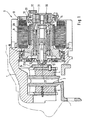
- Figure 1 shows an electromechanically actuated Floating caliper disc brake. The one described below Activation of this brake can of course also be done on everyone other types of disc and drum brakes transfer.
- the floating caliper disc brake consists of one opposite the brake disc 3 slidably mounted brake caliper 1, and an electric motor 2, the housing 8 on the brake caliper 1 is attached. Located on both sides of the brake disc each have a friction lining 4.5.
- the first friction lining 4 is on supported by a spindle 14 driven by the electric motor 2, so that it from the electric motor 2 against the brake disc 3 can be pressed.
- the second brake pad 5 is on Caliper 1 attached, and is from the reaction forces, the when you put the first disc 4 against the brake disc 3 are transferred to the saddle 1, against the other side the brake disc.
- the electric motor 2 is a permanently excited, electronic commutatable motor, the stator 9 of which is fixed in the housing 8 lies.
- the stator 9 is in a known manner by a Coil system realized.
- the rotor 10 consists of a Hollow shaft 15 which is rotatably mounted in the brake caliper. On on the outside of the hollow shaft are several permanent magnet segments 29 arranged, which is fixed to the hollow shaft 15th are connected.
- the magnetic field generated by the stator 9 acts with the permanent magnetic field of the magnetic segments 29 together and generates a rotation of the hollow shaft 15. This Rotation is done by means of a roller screw in one Transfer axial movement of the spindle 14. This is at the Inside of the hollow shaft 15 and on the outside of the Spindle 14 each have a thread, each in the thread of axially parallel thread rolls 12, 13 intervention.
- the spindle 14 is a hollow cylinder with an inner shoulder 20 executed.
- a calotte is supported on this paragraph 20 22 from which a push rod 23 abuts. This in turn leans against another calotte with its other end 22A, which is secured against rotation with the lining carrier 24 of the first Friction lining 4 is connected.
- the motor 2 is also equipped with a so-called resolver 30 Mistake.
- This consists of two coaxial to each other an air gap separate rings 31, 32, wherein the radially inner ring 31 via a holding element 33 is connected to the hollow shaft 15.
- the radially outer ring 32 is connected to the housing 8.
- resolvers are used to commutate the motor, to be able to carry out the energization of the stator 9 in such a way that a magnetic traveling field arises, and on the other hand to determine the relative angular position of the rotor.
- the resolver signal also delivers a statement about the position of the spindle 14 in the brake caliper 1.
- the brake just described is actuated by energizing the electric motor 2.
- the second friction lining 5 has one Contact pin, which through the surface to Disc extends. A similar contact pin is for the first brake pad 4 is provided, but not in FIG. 1 is shown. If the brake pads, as in Figure 1 shown on the disc, adjusts itself conductive contact between the tips of the contact pins and the brake disc. This can, as described in more detail below is explained, a circuit can be closed.
- the resolver 30 enables a relative angle measurement for the angular position of the rotor sleeve 15 and thus the position of the Spindle 14.
- the construction of the in Figure 1 described mechanics see no direct metrological Recording of the air play before. Due to lining wear and thermal influences find a change between the Assignment of the axial position of the spindle and brake clamping force instead of.
- Another problem is that when you turn on the control for the electromechanical The brake can be actuated initially to check the current air gap situation is completely unknown. This requires a determination the setting of the air gap immediately after switching on the control, because if the ventilation game is known, braking can be carried out much more sensitively, since the transition to actual braking on the correct angular position can take place. Knowing the exact size of the air gap is particularly necessary if the braking force to be exerted is not regulated but must be controlled.
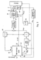
- the monitoring module 42 provides at a first output a target engine torque signal M M, target 51 and at a second output a target angle signal ⁇ to 52nd
- control signal S becomes 0 or 1 set.
- the contact signal is applied to input 55.
- control variable at input 54 that of a superordinate functional unit, not shown is set if necessary, e.g. then when the air game to be recorded and readjusted.
- the determination of a new zero position can be on can be realized in different ways.
- the target torque starts at one before defined starting value gradually increased until based on movement of the motor speed signal is determined or a defined upper limit for the Target torque is reached.
Landscapes
- Engineering & Computer Science (AREA)
- Mechanical Engineering (AREA)
- Transportation (AREA)
- General Engineering & Computer Science (AREA)
- Braking Arrangements (AREA)
- Braking Systems And Boosters (AREA)
Abstract
Description
- Figur 1
- den typischen Aufbau einer elektromotorisch betätigten Radbremse, und
- Figur 2
- einen Blockschaltbild zur Motoransteuerung.
Claims (6)
- System zum Steuern oder Regeln einer elektromotorischen Bremse, die eine erste Reibfläche aufweist, die an einem Teil ausgebildet ist, das sich mit dem abzubremsenden Teil bewegt, mit einer zweiten Reibfläche, die an einem Reibelement ausgebildet ist, das von einem Elektromotor gegen die erste Reibfläche bewegbar ist, wobei die erste und zweite Reibfläche ein Lüftspiel zueinander einhalten, mit Mitteln, die direkt oder indirekt den Rotordrehwinkel des Elektromotors erfassen, mit einem Kontaktfeststellungsmittel, das in der Lage ist, festzustellen, ob die erste Reibfläche an der zweiten Reibfläche anliegt und daraufhin ein Kontaktsignal generiert, dadurch gekennzeichnet, daß zur Bestimmung des Rotordrehwinkels, bei dem die erste Reibfläche an der zweiten Reibfläche anliegt, die Änderung der von den Mitteln zum Erfassen des Rotordrehwinkels abgeleiteten Rotordrehwinkelgeschwindigkeit beim Anlegen der ersten Reibfläche an die zweite Reibfläche ausgewertet wird.
- System nach Anspruch 1, dadurch gekennzeichnet, daß zur Bestimmung des Rotordrehwinkels, bei dem die erste Reibfläche an der zweiten Reibfläche anliegt, der Motor mit einem konstanten Drehmoment derart angesteuert wird, daß die zweite Reibfläche auf die erste Reibfläche zubewegt wird, und daß der Null-Durchgang der Winkelbeschleunigung als Basis für die Generierung eines Kontaktsignals verwandt wird.
- System nach Anspsruch 1, dadurch gekennzeichnet, daß die Ansteuerung des Motors so ausgelegt ist, daß er entweder mit einer definierten Drehzahl oder mit einem definierten Drehmoment betrieben werden kann.
- System nach Anspruch 3, dadurch gekennzeichnet, daß beim Ansprechen der Kontaktfeststellungsmittel der Motor unter Regelung bzw Steuerung der Winkelgeschwindigkeit auf das vorgegebene Lüftspiel zurückgefahren wird.
- System nach Anspruch 3, daduch gekennzeichnet, daß der Elektromotor über einen Servoverstärker angefahren wird, der über ein Schaltelement entweder auf die Betriebsart "Momentenregelung" oder aber auf die Betriebsart "Drehzahlregelung" geschaltet werden kann.
- System nach Anspruch 5, dadurch gekennzeichnet, daß die Steuerung ein Modul enthält, das entsprechende Schaltsignale an den Servoverstärker herausgibt.
Applications Claiming Priority (3)
| Application Number | Priority Date | Filing Date | Title |
|---|---|---|---|
| DE19536695 | 1995-09-30 | ||
| DE19536695A DE19536695A1 (de) | 1995-09-30 | 1995-09-30 | System zum Steuern oder Regeln einer elektromechanischen Bremse |
| PCT/EP1996/003978 WO1997012794A1 (de) | 1995-09-30 | 1996-09-11 | System zum steuern oder regeln einer elektromechanischen bremse |
Publications (2)
| Publication Number | Publication Date |
|---|---|
| EP0853572A1 EP0853572A1 (de) | 1998-07-22 |
| EP0853572B1 true EP0853572B1 (de) | 2000-12-06 |
Family
ID=7773831
Family Applications (1)
| Application Number | Title | Priority Date | Filing Date |
|---|---|---|---|
| EP96931786A Expired - Lifetime EP0853572B1 (de) | 1995-09-30 | 1996-09-11 | System zum steuern oder regeln einer elektromechanischen bremse |
Country Status (5)
| Country | Link |
|---|---|
| US (1) | US6279694B1 (de) |
| EP (1) | EP0853572B1 (de) |
| JP (1) | JP3892905B2 (de) |
| DE (2) | DE19536695A1 (de) |
| WO (1) | WO1997012794A1 (de) |
Cited By (2)
| Publication number | Priority date | Publication date | Assignee | Title |
|---|---|---|---|---|
| DE102004008383A1 (de) * | 2004-02-20 | 2005-09-15 | Estop Gmbh | Verfahren und System zum Kompensieren einer Veränderung des Übertragungsverhaltens eines elektronischen Bremssystems |
| DE102005051146B4 (de) * | 2005-10-26 | 2008-01-17 | Daimler Ag | Verfahren und Prüfvorrichtung zum Prüfen und Einstellen des Lüftspiels einer Radbremse eines Kraftfahrzeuges |
Families Citing this family (66)
| Publication number | Priority date | Publication date | Assignee | Title |
|---|---|---|---|---|
| US6003640A (en) | 1997-05-09 | 1999-12-21 | The B.F. Goodrich Company | Electronic braking system with brake wear measurement and running clearance adjustment |
| NL1006542C2 (nl) | 1997-07-10 | 1999-01-12 | Skf Ind Trading & Dev | Remklauw met slijtagecompensatie. |
| DE19730094A1 (de) | 1997-07-14 | 1999-01-21 | Itt Mfg Enterprises Inc | System zum Steuern oder Regeln einer elektromechanischen Bremse |
| DE19731696A1 (de) * | 1997-07-23 | 1999-02-11 | Knorr Bremse Systeme | Verschleißnachstellvorrichtung für Scheibenbremsen und Verfahren zum Steuern der Vorrichtung |
| DE19732168C2 (de) * | 1997-07-25 | 2003-06-18 | Lucas Ind Plc | Hydraulische Fahrzeugbremse mit Feststelleinrichtung und Verfahren zum Betreiben derselben |
| GB2334078A (en) * | 1997-10-15 | 1999-08-11 | Rover Group | Vehicle brake systems |
| GB9721723D0 (en) * | 1997-10-15 | 1997-12-10 | Rover Group | Vehicle brake systems |
| DE19751445A1 (de) * | 1997-11-20 | 1999-05-27 | Itt Mfg Enterprises Inc | Elektromechanisch betätigte Feststellbremse für Kraftfahrzeuge |
| DE19910048A1 (de) * | 1998-10-27 | 2000-05-04 | Continental Teves Ag & Co Ohg | Verfahren und Vorrichtung zur Überwachung der Bewegung eines Aktuators |
| WO2000025036A1 (de) * | 1998-10-27 | 2000-05-04 | Continental Teves Ag & Co. Ohg | Verfahren und vorrichtung zur überwachung der bewegung eines aktuators |
| WO2001014197A1 (de) * | 1999-08-25 | 2001-03-01 | Continental Teves Ag & Co. Ohg | Verfahren und regelsystem zum aufbringen definierten betätigungskräfte |
| US6969126B2 (en) * | 2000-02-28 | 2005-11-29 | Hitachi, Ltd. | Braking apparatus and method of controlling the same |
| JP3684985B2 (ja) * | 2000-02-28 | 2005-08-17 | 株式会社日立製作所 | ブレーキ装置 |
| JP4033281B2 (ja) | 2000-09-06 | 2008-01-16 | 日産自動車株式会社 | 制動装置 |
| WO2002088562A1 (de) * | 2001-04-26 | 2002-11-07 | Knorr-Bremse Systeme für Nutzfahrzeuge GmbH | Scheibenbremse mit elektromotorisch angetriebenem verschleissnachstellsystem |
| DE10123568A1 (de) * | 2001-05-15 | 2002-11-21 | Continental Teves Ag & Co Ohg | Verfahren und System zur Ansteuerung einer elektromechanisch betätigbaren Bremse für Kraftfahrzeuge |
| US8100232B2 (en) | 2001-08-16 | 2012-01-24 | Wabco Gmbh | Actuating device for a brake |
| DE10152423C2 (de) | 2001-10-24 | 2003-08-21 | Lucas Automotive Gmbh | Scheibenbremse |
| GB0130379D0 (en) * | 2001-12-20 | 2002-02-06 | Delphi Tech Inc | Electromechanical brake and the operation thereof |
| US20060117885A1 (en) * | 2001-12-21 | 2006-06-08 | Martin Robson | Actuator |
| JP2003194119A (ja) | 2001-12-28 | 2003-07-09 | Nissan Motor Co Ltd | 電動ブレーキ装置 |
| FR2835896B1 (fr) * | 2002-02-12 | 2005-06-10 | Delphi Tech Inc | Dispositif pour detecter un contact entre deux elements de frein d'un systeme de frenage |
| WO2003080415A1 (de) * | 2002-03-21 | 2003-10-02 | Lucas Automotive Gmbh | Elektrisch betätigbare fahrzeugbremse und verfahren zur steuerung einer elektrisch betätigbaren fahrzeugbremse |
| DE10214669B4 (de) * | 2002-04-03 | 2014-01-23 | Knorr-Bremse Systeme für Schienenfahrzeuge GmbH | Verfahren und Vorrichtung zur Ansteuerung einer elektrisch betätigten Verschleißnachstelleinrichtung |
| DE10261969B4 (de) * | 2002-06-24 | 2011-01-05 | Lucas Automotive Gmbh | Elektrisch betätigbare Fahrzeugbremse und Verfahren zur Steuerung einer elektrisch betätigbaren Fahrzeugbremse |
| DE10336125A1 (de) * | 2002-08-08 | 2004-02-26 | Asmo Co., Ltd. | Traktionssteueranlage |
| FR2851537B1 (fr) * | 2003-02-20 | 2006-04-07 | Delphi Tech Inc | Systeme de freinage electromecanique d'un vehicule et son procede de commande |
| AU2003253297A1 (en) * | 2003-07-31 | 2005-02-15 | Freni Brembo S.P.A | Method and apparatus for controlling a braking device in a vehicle and braking device |
| US7347304B2 (en) * | 2003-09-26 | 2008-03-25 | Haldex Brake Products Ab | System for control of brake actuator |
| EP1826081B1 (de) * | 2003-10-15 | 2011-04-20 | Honeywell Inc. | Verfahren zur Verstärkung eines Motorsollmoments bei transienter Positionsabweichung |
| US7129658B2 (en) * | 2003-10-15 | 2006-10-31 | Honeywell International Inc. | Electro-mechanical actuator braking apparatus and method using motor commutation sensor output to derive piston displacement |
| GB0324243D0 (en) * | 2003-10-16 | 2003-11-19 | Meritor Heavy Vehicle Braking | A control system and method for a disc brake |
| FR2862281B1 (fr) * | 2003-11-19 | 2007-03-16 | Messier Bugatti | Procede d'actionnement d'un frein d'aeronef equipe d'au moins un actionneur electromecanique |
| US6959969B2 (en) * | 2004-03-05 | 2005-11-01 | Delphi Technologies, Inc. | System and method for controlling a brake |
| US20050216160A1 (en) * | 2004-03-23 | 2005-09-29 | Delphi Technologies Inc. | Method for detecting electric-mechanical-brake pad drag and/or calculating actuator efficiency |
| JP4463812B2 (ja) | 2004-06-21 | 2010-05-19 | 日立オートモティブシステムズ株式会社 | 電動ブレーキ |
| US20060090968A1 (en) * | 2004-11-01 | 2006-05-04 | Meritor Heavy Vehicle Braking Systems (Uk) Ltd. | Brake assembly with brake pad position and wear sensor |
| FR2880603B1 (fr) * | 2005-01-11 | 2007-03-16 | Messier Bugatti Sa | Procede de gestion de l'effort de parc dans un systeme de freinage de vehicule equipe de freins electriques |
| US20070052289A1 (en) * | 2005-09-07 | 2007-03-08 | Haldex Brake Products, Ab. | Brake monitoring and control system |
| US7726748B2 (en) * | 2005-09-26 | 2010-06-01 | Zumberge Jon T | Low force level detection system and method |
| US7475760B2 (en) * | 2005-10-04 | 2009-01-13 | Delphi Technologies, Inc. | Pad contact detection method |
| DE102005048338A1 (de) * | 2005-10-10 | 2007-04-12 | Robert Bosch Gmbh | Geschwindigkeits- und Abstandsregler für Kraftfahrzeuge |
| US7374254B2 (en) * | 2005-12-05 | 2008-05-20 | Delphi Technologies, Inc. | Electric caliper position control with adaptive estimation |
| US20070235267A1 (en) * | 2006-04-11 | 2007-10-11 | Goodrich Corporation | Controller for electromechanical braking system with running clearance adjustment and method |
| US7353101B2 (en) * | 2006-04-18 | 2008-04-01 | Honeywell International Inc. | Methods and apparatus to control electro-mechanical brakes |
| DE102007036907A1 (de) * | 2007-08-06 | 2009-02-12 | Bpw Bergische Achsen Kg | Vorrichtung und Verfahren zur Erkennung des Leerhubs von Fahrzeugbremsen auflaufgebremster Anhängerfahrzeuge |
| EP2644929A1 (de) * | 2012-03-28 | 2013-10-02 | Meritor Heavy Vehicle Braking Systems (UK) Limited | Verfahren zum Bestimmen des Anlegepunkts einer Bremse |
| EP3575626B1 (de) | 2012-03-28 | 2025-08-27 | Meritor Heavy Vehicle Braking Systems (UK) Limited | Verfahren zur bestimmung der verbleibenden lebensdauer eines bremslements |
| TWI485337B (zh) * | 2012-10-29 | 2015-05-21 | Lioho Machine Works Ltd | Disc Brake Brake |
| DE102013012104B4 (de) | 2013-07-12 | 2022-10-06 | Knorr-Bremse Systeme für Nutzfahrzeuge GmbH | Verfahren zum Ermitteln eines Lüftspiels einer Fahrzeugbremse und Fahrzeugbremse mit einer Vorrichtung zur Ermittlung eines Lüftspiels |
| US9457782B2 (en) * | 2014-03-14 | 2016-10-04 | Arvinmeritor Technology, Llc | Brake system and method of control with air gap estimation |
| KR101501533B1 (ko) * | 2014-04-28 | 2015-03-18 | 재단법인대구경북과학기술원 | 전기기계 브레이크의 마모 보상을 위한 모터 제어 시스템 및 그 제어 방법 |
| DE102014210557B4 (de) | 2014-06-04 | 2026-03-12 | Robert Bosch Gmbh | Sensorvorrichtung für einen elektromechanischen Bremskraftverstärker und Verfahren zum Ermitteln eines Verlustmoments eines elektromechanischen Bremskraftverstärkers eines Bremssystems |
| DE102014214741B4 (de) * | 2014-07-28 | 2026-03-05 | Robert Bosch Gmbh | Verfahren und Vorrichtung zum Betreiben einer Parkbremse eines Kraftfahrzeugs |
| US10570974B2 (en) | 2015-04-17 | 2020-02-25 | Goodrich Corporation | Brake position and wear detection systems and methods |
| WO2017081827A1 (ja) * | 2015-11-13 | 2017-05-18 | 株式会社五十嵐電機製作所 | 電動パーキングブレーキ装置 |
| JP6678039B2 (ja) * | 2016-02-10 | 2020-04-08 | Ntn株式会社 | 電動ブレーキ装置 |
| EP3251908B1 (de) | 2016-06-03 | 2021-01-20 | Meritor Heavy Vehicle Braking Systems (UK) Limited | Bremssystem und verfahren zur steuerung mit luftspaltschätzung |
| US10800386B2 (en) | 2017-07-24 | 2020-10-13 | Goodrich Corporation | Brake position system |
| US10493962B2 (en) * | 2017-07-24 | 2019-12-03 | Goodrich Corporation | Brake position system |
| JP7056367B2 (ja) * | 2018-05-17 | 2022-04-19 | トヨタ自動車株式会社 | 認識エラー検出装置、電動ブレーキ制御装置 |
| CN208503318U (zh) * | 2018-05-29 | 2019-02-15 | 罗伯特·博世有限公司 | 汽车刹车片厚度检测系统 |
| DE102019100481A1 (de) * | 2019-01-10 | 2020-07-16 | Wabco Europe Bvba | Verfahren zum Einstellen eines Lüftspiels einer elektromechanischen Bremse sowie betreffende Bremse und Steuergerät |
| CN112550256B (zh) * | 2020-12-17 | 2021-10-12 | 江苏大学 | 一种适用于abs的高稳定emb线控制动系统及其控制方法 |
| CN117813224A (zh) * | 2021-08-05 | 2024-04-02 | 大陆汽车科技有限公司 | 用于形成特别是用于电动的机动车辆驻车制动器epb的特殊制动准备位置的方法和设备 |
| CN117184014A (zh) * | 2023-10-13 | 2023-12-08 | 苏州坐标系智能科技有限公司 | 一种电子机械制动系统及其零位自适应控制方法 |
Family Cites Families (14)
| Publication number | Priority date | Publication date | Assignee | Title |
|---|---|---|---|---|
| FR2520076A1 (fr) * | 1982-01-18 | 1983-07-22 | Michelin & Cie | Avertisseur d'usure et de lechage pour frein a couronne ou a disque |
| DE3410006A1 (de) * | 1984-03-19 | 1985-09-19 | Alfred Teves Gmbh, 6000 Frankfurt | Verfahren zur steuerung einer bremsanlage fuer kraftfahrzeuge und vorrichtung zur durchfuehrung des verfahrens |
| US4568863A (en) | 1984-06-27 | 1986-02-04 | Goodyear Aerospace Corporation | Controller for electric brake motors |
| GB8419374D0 (en) | 1984-07-30 | 1984-09-05 | Westinghouse Brake & Signal | Actuator system |
| US4850457A (en) * | 1987-10-07 | 1989-07-25 | Allied-Signal Inc. | Electrically actuated disc brake |
| US4944372A (en) * | 1988-12-15 | 1990-07-31 | Allied-Signal Inc. | Electrically actuated braking system |
| JPH0341233A (ja) * | 1989-07-06 | 1991-02-21 | Honda Motor Co Ltd | 電動ブレーキ |
| US4995483A (en) * | 1989-12-18 | 1991-02-26 | Aircraft Braking Systems Corporation | Motor position feedback controlled electrically actuated aircraft brake |
| JP2835173B2 (ja) * | 1990-11-13 | 1998-12-14 | 本田技研工業株式会社 | 車両のブレーキ制御装置 |
| US5390992A (en) * | 1993-03-04 | 1995-02-21 | General Motors Corporation | Vehicle electric brake system with static brake torque control |
| US5366280A (en) * | 1994-02-14 | 1994-11-22 | General Motors Corporation | Method of adaptively homing brake actuators |
| US5423600A (en) * | 1994-02-14 | 1995-06-13 | General Motors Corporation | Brake system with brake gain shifting |
| DE19511287B4 (de) * | 1994-07-21 | 2004-05-06 | Continental Teves Ag & Co. Ohg | Elektromechanische betätigbare Scheibenbremse |
| DE19536694A1 (de) * | 1995-09-30 | 1997-04-03 | Teves Gmbh Alfred | Steuer- bzw. Regelsystem für eine elektromotorisch betätigte Radbremse |
-
1995
- 1995-09-30 DE DE19536695A patent/DE19536695A1/de not_active Withdrawn
-
1996
- 1996-09-11 WO PCT/EP1996/003978 patent/WO1997012794A1/de not_active Ceased
- 1996-09-11 DE DE59606195T patent/DE59606195D1/de not_active Expired - Lifetime
- 1996-09-11 EP EP96931786A patent/EP0853572B1/de not_active Expired - Lifetime
- 1996-09-11 US US09/043,266 patent/US6279694B1/en not_active Expired - Fee Related
- 1996-09-11 JP JP51391997A patent/JP3892905B2/ja not_active Expired - Fee Related
Cited By (2)
| Publication number | Priority date | Publication date | Assignee | Title |
|---|---|---|---|---|
| DE102004008383A1 (de) * | 2004-02-20 | 2005-09-15 | Estop Gmbh | Verfahren und System zum Kompensieren einer Veränderung des Übertragungsverhaltens eines elektronischen Bremssystems |
| DE102005051146B4 (de) * | 2005-10-26 | 2008-01-17 | Daimler Ag | Verfahren und Prüfvorrichtung zum Prüfen und Einstellen des Lüftspiels einer Radbremse eines Kraftfahrzeuges |
Also Published As
| Publication number | Publication date |
|---|---|
| US6279694B1 (en) | 2001-08-28 |
| DE59606195D1 (de) | 2001-01-11 |
| WO1997012794A1 (de) | 1997-04-10 |
| DE19536695A1 (de) | 1997-04-03 |
| JPH11513337A (ja) | 1999-11-16 |
| JP3892905B2 (ja) | 2007-03-14 |
| EP0853572A1 (de) | 1998-07-22 |
Similar Documents
| Publication | Publication Date | Title |
|---|---|---|
| DE19536695A1 (de) | System zum Steuern oder Regeln einer elektromechanischen Bremse | |
| EP0853571B1 (de) | Steuer- bzw. regelsystem für eine elektromotorisch betätigte radbremse | |
| DE102006003811B4 (de) | Steuerungsverfahren eines Bremssystems mit Motorantrieb | |
| DE60130390T2 (de) | Bremsvorrichtung und Verfahren zu seiner Regelung | |
| EP3898360B1 (de) | Elektromechanische bremsenanlage | |
| DE60203591T2 (de) | Elektrisches Bremssystem | |
| DE69929290T2 (de) | Fahrzeugbremse mit elektromotorischer Regelung des Luftspiels | |
| DE60220199T2 (de) | Bremsnachsteller | |
| DE102007029662B4 (de) | Verfahren zum Betrieb eines motorbetriebenen Scheibenbremssystems | |
| DE10228115B4 (de) | Elektrisch betätigbare Fahrzeugbremse und Verfahren zur Steuerung einer elektrisch betätigbaren Fahrzeugbremse | |
| DE10335671A1 (de) | Elektrische Parkbremsanlage und Verfahren zum Steuern der elektrischen Parkbremsanlage | |
| DE19826053A1 (de) | Verfahren und Vorrichtung zur Steuerung einer Radbremse | |
| EP3509916A1 (de) | Technik zur charakterisierung einer elektromechanischen aktuatoreinheit für eine fahrzeugbremse | |
| DE10202707A1 (de) | Elektrische Bremsvorrichtung und Verfahren zum Steuern Derselben | |
| DE102017128714A1 (de) | Elektrisches bremssystem und verfahren des einstellens von druckkraft-strom-charakteristika | |
| EP1141574B1 (de) | Elektromechanische kraftfahrzeug-bremsvorrichtung | |
| EP3645357B1 (de) | Verfahren und eine vorrichtung zum betreiben einer automatisierten feststellbremse | |
| DE102022123977A1 (de) | Verfahren zum Betreiben eines Fahrzeugbremssystems und ein Fahrzeugbremssystem | |
| WO2019197226A1 (de) | Aufzugsanlage | |
| DE4418397C2 (de) | Elektrische Bremsanlage für Fahrzeuge | |
| DE19858763C2 (de) | Verfahren zum Steuern eines elektromagnetischen Radbremsaktors in einem Kraftfahrzeug | |
| DE10157324A1 (de) | Schwimmsattelscheibenbremse mit Vorrichtung zur Lüftspieleinstellung sowie zugehöriges Verfahren | |
| DE102013222718B4 (de) | Elektromechanische Radbremse | |
| DE102005060024B4 (de) | Verfahren und Bremssystem zum Einstellen einer Nullposition einer Reibungsfläche | |
| DE102011004781A1 (de) | Regel- bzw. Steuergerät für eine Feststellbremse in einem Fahrzeug |
Legal Events
| Date | Code | Title | Description |
|---|---|---|---|
| PUAI | Public reference made under article 153(3) epc to a published international application that has entered the european phase |
Free format text: ORIGINAL CODE: 0009012 |
|
| 17P | Request for examination filed |
Effective date: 19980504 |
|
| AK | Designated contracting states |
Kind code of ref document: A1 Designated state(s): DE FR GB |
|
| RAP1 | Party data changed (applicant data changed or rights of an application transferred) |
Owner name: CONTINENTAL TEVES AG & CO. OHG |
|
| 17Q | First examination report despatched |
Effective date: 19990212 |
|
| GRAG | Despatch of communication of intention to grant |
Free format text: ORIGINAL CODE: EPIDOS AGRA |
|
| 17Q | First examination report despatched |
Effective date: 19990212 |
|
| GRAG | Despatch of communication of intention to grant |
Free format text: ORIGINAL CODE: EPIDOS AGRA |
|
| GRAG | Despatch of communication of intention to grant |
Free format text: ORIGINAL CODE: EPIDOS AGRA |
|
| GRAH | Despatch of communication of intention to grant a patent |
Free format text: ORIGINAL CODE: EPIDOS IGRA |
|
| GRAH | Despatch of communication of intention to grant a patent |
Free format text: ORIGINAL CODE: EPIDOS IGRA |
|
| GRAA | (expected) grant |
Free format text: ORIGINAL CODE: 0009210 |
|
| AK | Designated contracting states |
Kind code of ref document: B1 Designated state(s): DE FR GB |
|
| GBT | Gb: translation of ep patent filed (gb section 77(6)(a)/1977) |
Effective date: 20001206 |
|
| REF | Corresponds to: |
Ref document number: 59606195 Country of ref document: DE Date of ref document: 20010111 |
|
| ET | Fr: translation filed | ||
| PGFP | Annual fee paid to national office [announced via postgrant information from national office to epo] |
Ref country code: GB Payment date: 20010823 Year of fee payment: 6 |
|
| PLBE | No opposition filed within time limit |
Free format text: ORIGINAL CODE: 0009261 |
|
| STAA | Information on the status of an ep patent application or granted ep patent |
Free format text: STATUS: NO OPPOSITION FILED WITHIN TIME LIMIT |
|
| 26N | No opposition filed | ||
| REG | Reference to a national code |
Ref country code: GB Ref legal event code: IF02 |
|
| PG25 | Lapsed in a contracting state [announced via postgrant information from national office to epo] |
Ref country code: GB Free format text: LAPSE BECAUSE OF NON-PAYMENT OF DUE FEES Effective date: 20020911 |
|
| GBPC | Gb: european patent ceased through non-payment of renewal fee |
Effective date: 20020911 |
|
| REG | Reference to a national code |
Ref country code: DE Ref legal event code: R231 Ref document number: 59606195 Country of ref document: DE |
|
| PGFP | Annual fee paid to national office [announced via postgrant information from national office to epo] |
Ref country code: FR Payment date: 20110927 Year of fee payment: 16 Ref country code: DE Payment date: 20110930 Year of fee payment: 16 |
|
| PG25 | Lapsed in a contracting state [announced via postgrant information from national office to epo] |
Ref country code: DE Free format text: LAPSE BECAUSE OF THE APPLICANT RENOUNCES Effective date: 20111029 |
|
| REG | Reference to a national code |
Ref country code: FR Ref legal event code: ST Effective date: 20130531 |
|
| PG25 | Lapsed in a contracting state [announced via postgrant information from national office to epo] |
Ref country code: FR Free format text: LAPSE BECAUSE OF NON-PAYMENT OF DUE FEES Effective date: 20121001 |