EP0844034A2 - Verfahren und Einrichtung zum Herstellen von Löchern am Umfang eines Hohlprofiles - Google Patents
Verfahren und Einrichtung zum Herstellen von Löchern am Umfang eines Hohlprofiles Download PDFInfo
- Publication number
- EP0844034A2 EP0844034A2 EP97118614A EP97118614A EP0844034A2 EP 0844034 A2 EP0844034 A2 EP 0844034A2 EP 97118614 A EP97118614 A EP 97118614A EP 97118614 A EP97118614 A EP 97118614A EP 0844034 A2 EP0844034 A2 EP 0844034A2
- Authority
- EP
- European Patent Office
- Prior art keywords
- hollow profile
- slug
- stamp
- hole
- internal high
- Prior art date
- Legal status (The legal status is an assumption and is not a legal conclusion. Google has not performed a legal analysis and makes no representation as to the accuracy of the status listed.)
- Withdrawn
Links
- 238000000034 method Methods 0.000 title claims abstract description 26
- 238000004519 manufacturing process Methods 0.000 title claims description 12
- 239000012530 fluid Substances 0.000 claims abstract description 9
- 239000000463 material Substances 0.000 claims description 15
- 238000005520 cutting process Methods 0.000 claims description 12
- 230000006835 compression Effects 0.000 claims description 5
- 238000007906 compression Methods 0.000 claims description 5
- 238000004049 embossing Methods 0.000 claims description 4
- 239000007788 liquid Substances 0.000 claims description 4
- 238000003825 pressing Methods 0.000 claims 2
- 238000004804 winding Methods 0.000 claims 1
- 238000004080 punching Methods 0.000 abstract description 8
- 241000237858 Gastropoda Species 0.000 description 13
- 230000008569 process Effects 0.000 description 7
- 230000015572 biosynthetic process Effects 0.000 description 5
- 230000035515 penetration Effects 0.000 description 4
- 238000012545 processing Methods 0.000 description 3
- 238000012549 training Methods 0.000 description 3
- 230000009471 action Effects 0.000 description 2
- 230000008901 benefit Effects 0.000 description 2
- 238000006073 displacement reaction Methods 0.000 description 2
- 230000000694 effects Effects 0.000 description 2
- 238000007789 sealing Methods 0.000 description 2
- TVEXGJYMHHTVKP-UHFFFAOYSA-N 6-oxabicyclo[3.2.1]oct-3-en-7-one Chemical compound C1C2C(=O)OC1C=CC2 TVEXGJYMHHTVKP-UHFFFAOYSA-N 0.000 description 1
- 206010020772 Hypertension Diseases 0.000 description 1
- 238000005336 cracking Methods 0.000 description 1
- 238000009795 derivation Methods 0.000 description 1
- 238000000605 extraction Methods 0.000 description 1
- 238000003780 insertion Methods 0.000 description 1
- 230000037431 insertion Effects 0.000 description 1
- 238000007689 inspection Methods 0.000 description 1
- 230000010354 integration Effects 0.000 description 1
- NLYAJNPCOHFWQQ-UHFFFAOYSA-N kaolin Chemical compound O.O.O=[Al]O[Si](=O)O[Si](=O)O[Al]=O NLYAJNPCOHFWQQ-UHFFFAOYSA-N 0.000 description 1
- 238000003754 machining Methods 0.000 description 1
- 230000002093 peripheral effect Effects 0.000 description 1
- 230000009467 reduction Effects 0.000 description 1
- 238000000926 separation method Methods 0.000 description 1
- 238000012360 testing method Methods 0.000 description 1
- 230000007704 transition Effects 0.000 description 1
- 230000003313 weakening effect Effects 0.000 description 1
- 239000002347 wear-protection layer Substances 0.000 description 1
Images


Classifications
-
- B—PERFORMING OPERATIONS; TRANSPORTING
- B21—MECHANICAL METAL-WORKING WITHOUT ESSENTIALLY REMOVING MATERIAL; PUNCHING METAL
- B21D—WORKING OR PROCESSING OF SHEET METAL OR METAL TUBES, RODS OR PROFILES WITHOUT ESSENTIALLY REMOVING MATERIAL; PUNCHING METAL
- B21D28/00—Shaping by press-cutting; Perforating
- B21D28/24—Perforating, i.e. punching holes
- B21D28/28—Perforating, i.e. punching holes in tubes or other hollow bodies
-
- Y—GENERAL TAGGING OF NEW TECHNOLOGICAL DEVELOPMENTS; GENERAL TAGGING OF CROSS-SECTIONAL TECHNOLOGIES SPANNING OVER SEVERAL SECTIONS OF THE IPC; TECHNICAL SUBJECTS COVERED BY FORMER USPC CROSS-REFERENCE ART COLLECTIONS [XRACs] AND DIGESTS
- Y10—TECHNICAL SUBJECTS COVERED BY FORMER USPC
- Y10T—TECHNICAL SUBJECTS COVERED BY FORMER US CLASSIFICATION
- Y10T83/00—Cutting
- Y10T83/04—Processes
- Y10T83/0448—With subsequent handling [i.e., of product]
- Y10T83/0457—By retaining or reinserting product in workpiece
-
- Y—GENERAL TAGGING OF NEW TECHNOLOGICAL DEVELOPMENTS; GENERAL TAGGING OF CROSS-SECTIONAL TECHNOLOGIES SPANNING OVER SEVERAL SECTIONS OF THE IPC; TECHNICAL SUBJECTS COVERED BY FORMER USPC CROSS-REFERENCE ART COLLECTIONS [XRACs] AND DIGESTS
- Y10—TECHNICAL SUBJECTS COVERED BY FORMER USPC
- Y10T—TECHNICAL SUBJECTS COVERED BY FORMER US CLASSIFICATION
- Y10T83/00—Cutting
- Y10T83/04—Processes
- Y10T83/0596—Cutting wall of hollow work
-
- Y—GENERAL TAGGING OF NEW TECHNOLOGICAL DEVELOPMENTS; GENERAL TAGGING OF CROSS-SECTIONAL TECHNOLOGIES SPANNING OVER SEVERAL SECTIONS OF THE IPC; TECHNICAL SUBJECTS COVERED BY FORMER USPC CROSS-REFERENCE ART COLLECTIONS [XRACs] AND DIGESTS
- Y10—TECHNICAL SUBJECTS COVERED BY FORMER USPC
- Y10T—TECHNICAL SUBJECTS COVERED BY FORMER US CLASSIFICATION
- Y10T83/00—Cutting
- Y10T83/384—By tool inside hollow work
- Y10T83/395—One tool having only rectilinear motion[s]
Definitions
- the invention relates to a method for producing holes on the circumference of a hollow profile according to the preamble of the claim 1 and a device for this according to the preamble of Claim 12.
- a generic method or a generic device is known from US 4,989,482. This will follow a forming process using hydroforming at a Internal pressure in the range between about 7 and 700 bar for generation a hole in the circumference of that still in the forming tool Hollow profile a stamp on the hollow profile wall from the outside led, which there under the flat loading of the Stamp is pressed into the interior of the hollow profile.
- the stamp has a channel which acts on the hollow profile with a recessed face with the atmosphere connects. This results in between the face of the punch in the trough area and the hollow profile interior Pressure difference that the hollow profile to the surrounding the trough presses annular contact surface of the end face of the stamp.
- the elastic limit becomes of the hollow profile material reached at their Exceed the hollow profile wall around the point of application of the stamp tears around to form a hole. Because of the uneven hole wall of the hole created however, there is no adequate sealing when pressed in of the stamp between the outside of the hollow profile and the the die-bearing die created space and the Stamp guide of the die opposite the interior of the fluid pressure Interior of the hollow profile, so that despite the radial contact of the hole wall on the circumference of the stamp Pressure drop occurs within the hollow profile. This will the pressure difference between the atmosphere and the hollow profile interior so low that the suction effect of the stamp on the perforated slug is lifted, at least to a considerable extent is reduced.
- the slug detaches from Stamp and falls into the interior of the hollow profile.
- the perforated slug adheres with little force the face of the stamp.
- the punch slug gets into the hole again by means of a stamp.
- This succeeds but only in part, as they face the hollow profile interior curved hole wall of the by withdrawing the stamp provides resistance to the return movement of the slug, due to the low suction force mentioned above with the pressure compensation of the punch from the slug takes off.
- the slug even falls - without finding a hold on the hole wall - in the hollow profile interior inside.
- the clamping effect in this is small.
- the invention has for its object a generic To further develop a method and a generic device, that the perforated slug generated during punching is easier Way removed from the hydroforming tool can.
- the task is according to the invention by the features of the claim 1 regarding the procedure and the features of claim 12 with respect to the device.
- the perforated hole can be made without the aid of a fluidic internal high pressure in the preliminarily generated hole in such a way be jammed that the hollow profile the hydroforming tool can be removed without the slug falls out of the hole.
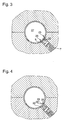
- FIG. 1 shows a two-part internal high-pressure forming tool 1 shown, which consists of an upper tool 2 and a lower tool 3 consists of the two halves of the tool 1 form.
- the dividing surface 21 of the upper and lower tools 2,3 is aligned horizontally.
- trained engraving 4 is a tubular hollow profile 5 used with a circular cross section.
- the hollow profile can also 5 be bent one or more times over its length.
- a machined guide hole 6 incorporated, which is aligned radially to the engraving 4 and in this flows out.
- a cutting punch 7 is in the guide bore 6 slidably guided.
- the cutting punch 7 lies with little Play on the wall of the guide hole 6, wherein this and / or the circumference of the stamp to reduce wear and to reduce friction between the two friction partners Stamp 7 and guide bore wall with a wear protection layer can be provided, the sliding properties of the stamp 7 in the guide bore 6 increased.
- the pilot hole 6 can also at different angles to the hollow profile axis located and need not necessarily be radially aligned. The radial alignment is, however, for simple training of the Stamp 7 cheap with a tubular hollow profile 5.
- the stamp 7 is cylindrical with a circular cross section. On its face 8 facing the engraving 4 the stamp 7 one with the outside 34 with the circumference of the Stamp 7 aligned ring cutting edge 9, which in the from Fig. 1 apparent non-use position of the stamp 7 on the outside 10 of the hollow profile 5 is applied continuously and ends flush with the engraving 4.
- the ring cutter 9 delimits a trough 11, the bottom of which is from the end face 8 is formed. The trough 11 and at the same time the End face 8 is concave in shape and depth trained that the wall piece later acted upon by the stamp 7 the hollow profile 5 as a slug 26 almost entirely can be included.
- the stamp 7 has an axial bore 12 in which a stamp-like plunger 13 is guided with little play.
- a stamp-like plunger 13 is guided with little play.
- the Tappet 13 is secured by a retaining bolt 14 which is in a Cross bore 15 of the punch 7 is pressed.
- the plunger 13 has an axially extending Elongated hole 16, the ends 17,18 of the stops on the retaining bolt 14 form.
- the plunger 13 is on the rear side 19 of a compression spring 20 is supported or by this for engraving 4 driven out.
- the support and the drive of the ram 13 can also be hydraulic, pneumatic or by a Slider member done mechanically.
- the plunger 13 is also located with its end face 35 in the non-use position of the stamp 7 on the hollow profile 5, the end 18 of the elongated hole 16 abuts the retaining bolt 14.
- the hollow profile 5 begins in the trough 11 of the still in Expand the non-use position of the stamp 7 (Fig. 2).
- the plunger 13 becomes its other stop, thus against its slot end 17 against the retaining bolt 14 against shifted the force of the compression spring 20, which in a biased Condition passes.
- the plunger 13 acts as it were as a counterhold, as he did from the formation of T-pieces is known by hydroforming. It forms a bump 22 on the hollow profile 5, while the flow of the hollow profile material into the depression 11 in the edge region 23 the guide hole 6 at the transition to the engraving 4 by pulling the Material is thinned over the guide hole edge.
- the End face 35 of the plunger 13 then forms in its non-use position together with the face 8 of the stamp 7 the reason of the expansion trough 11.
- the stamp 7 is engraved towards the 4 undiminished high internal high pressure by means of a high pressure generating hydraulics acting as drive means shifted until the Ring cutting edge 9 in the hollow profile wall 24 in the form of a piercing cuts.
- the incision leaves a thin area 25 arise in the hollow profile wall 24, at the same time the Bump 22 of the future hole 26 by the stamp movement something in the direction of the interior 27 of the hollow section 5 is pushed back (Fig. 3).
- the creation of the thin point 25 is due to the previous thinning of the hollow profile material supported in the edge area 23 by the expansion of the hollow profile 5, the incision then only with a lower penetration depth must be done as the incision without previous Thinning out.
- the ring cutter 9 is also in terms of their wear and tear somewhat spared.
- the hypertension avoids that when piercing the stamp 7 the Hollow profile wall 24 in the area that to be generated Hole 29 adjoins laterally, bent towards the hollow profile interior 27 and thus the uniform course of the outside 10 of the hollow profile 5 deformed
- the stamp 7 After creating the thin point 25, the stamp 7 is impact or suddenly pulled back into the non-use position, whereupon the thin area 25 tears all around.
- the wall thickness of the Thin point 25 is dimensioned or so unstable that the perforated slug 26 easily by the action alone torn out of the hollow profile wall 24 with the internal high pressure becomes. Because of the clean cut through the ring cutting edge 9 is the wall 28 of the hole 29 created at the end to the outside 10 of the hollow profile 5 flat and sharp-edged. The outside 10 remains until the hole formation constant pressure of the internal high pressure on the engraving 4 undeformed also in the area of the hole wall 28, so that the shape course the hollow profile 5 is maintained after the perforation.
- the jerky retraction of the stamp 7 is advantageous the inertia of the still in the hollow profile wall 24 hole punch 26 and the short time between the outside 10 of the hollow profile 5 and the stamp 7 resulting negative pressure used for tearing, so that by the the pressure difference between the hollow profile interior was increased 27 and that of the outside 10 of the hollow profile 5 and the stamp 7 formed space of the slug 26 also suddenly - without having contact with the stamp 7 - is torn out of the hollow profile wall 24 even more easily.
- the wall 24 of the hollow profile 5 for producing a hole 29 of smaller cross-sectional area is weakened more than in manufacturing a hole 29 of larger cross-sectional area. The definition or the vote is such that the holes 29 arise practically simultaneously.
- the hole slugs are separated 26 do not happen completely, they hang at most still on a thin wall thread 30 (Fig. 4), which later the removal of the perforated hollow profile 5 from the forming tool 1 can be capped.
- the possible result Burr is of low priority for the manufacturing quality of the hollow profile 5 Significance because the ridge is due to the previous one Cutting through the ring edge 9 of the punch 7 is not in the area of the outside 10 of the hollow profile 5.
- the inventive method are simple any hole geometries can be formed, only the stamp 7 on its end face 8 and its guide bore 6 accordingly must be trained.
- the stamp 7 can in the non-use position in such a way Guide hole 6 may be arranged that of the hollow profile wall 24 separate slugs 26 only partially the hollow profile 5 can leave.
- the slug 26 is about 3/10 - 5/10 of the wall thickness of the hollow profile wall 24 still in Hole 29.
- the process of separating the slug 26 from the hollow profile wall 24 is now complete. After that, the internal high pressure preferably within the hollow profile interior 27 lowered to atmospheric pressure, after which the plunger 13 on the Hole slug 26 is moved. This is entirely from the plunger 13 pressed back into the hole 29 so that a protrusion of the Punched hole 26 avoided on the outside 10 of the hollow profile 5 is a removal of the machined hollow profile would hinder or even prevent.
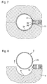
- a stamp 36 can be used be the 8 on its face instead of the ring cutter 9 has an annular wall 31 as penetrant, which is rectangular in cross section and with its outside 32 is flush with the circumference of the stamp, as shown in Fig. 5 can be seen.
- the stamp 36 is already in Position of use, being driven by a high pressure generator Hydraulics - by means of the annular wall 31 in the hollow profile wall 24 has penetrated and through the embossing a forming the thin point 25, according to the shape of the Wall 32 creates circumferential wall weakening.
- the opening takes place here by lifting the upper tool 2, after which the machined Hollow profile 5 can be removed.
- the perforation axis runs thereby in the division surface 21 of the upper and lower tool 2, 3 (Fig. 8). This applies to the creation of several holes 29 First embodiment said in the correspondingly transmitted Senses.
- the plunger 13 can be arranged locally separately from the punch 7 or 36 be and for the exercise of its function in the use position be moved. The same is also conceivable that from the stamp 7 or 36 itself takes over the plunger function becomes. As a result, a component, the plunger 13, and its Drive saved. However, this option is mentioned practicable only when the slug 26 is not in the Has trough 11, 33 of the stamp 7, or 36 jammed. Thus forms the integration of the plunger 13 in the stamp 7 or 36 not only a simple one for pushing back the slug 26 structural solution, but also yields - apart from the better Process economics with respect to the first listed above Possibility - the functional advantage that the plunger 13 in Stamp 7 or 36 pinched perforated slug 26 releases.
- the holes 29 can be produced both in the case of hollow profiles 5, which were made in other tools as well take place with hollow sections 5, which first by hydroforming from a hollow inserted in the forming tool 1 Blank and then calibrated.
- the Hollow section 5 can be made of assembled, preferably welded Half shells or extruded profiles exist.
- the hollow profile 5 after insertion into the forming tool 1 can be expanded by high pressure, which thereby one protruding into the engraving 4 of the forming tool 1 stamp 7 or 36 supported on the back, whereby due to the penetration of the stamp 7, 36 into the hollow profile wall 24 the thin point 25 of the hollow profile wall 24 is trained.
- the Stamp 7, or 36 withdrawn, after which the thin section 25 under Influence of the internal high pressure tears and the resulting one Punch 26 is torn outwards.
- the hole slug 26 is when completely removed from the hollow profile wall 24 into the trough 11 or 33 of the stamp 7 or 36 pressed inside the guide bore 6 and there jammed. When partially removing the slug 26 gives the stamp 7, or 36 through the permanent system on Punch 26 sufficient hold so that this is not an option takes place in an uncontrolled manner in the interior 27 of the hollow profile 5 or to get into the forming tool 1.
- the forming tool is an embodiment at atmospheric pressure 1 opened, after which the hollow profile 5 are removed can.
- the perforated slug can now be used 26 using a simple device conventional from the Hollow profile 5 are pushed out without causing deformation of the hollow profile 5 comes in the edge region of the hole 29.
- the pushing out or the pulling out of the slug 26 can for example in the case of essentially straight lines Hollow sections 5 are of sufficiently large cross section, wherein in a retractable into the hollow profile 5 designed as a lance Device 37 one or more displaceable ejector stamps 38 are arranged, which for this purpose in transverse bores 39 Lance are guided (Fig. 9).
- the ejector stamp 38 communicates its plate-shaped head 40, which with its circumference on the Cross bore wall 41 is sealingly circumferential, the cross bore 39 in two sub-rooms 42, 43.
- the subspace 42 has one Pressure port 44, by means of which the sub-space 42 and thus the head 40 of the ejector stamp 38 with compressed air or one Hydraulic fluid can be applied.
- the ejector stamp 38 When excess pressure is exerted the ejector stamp 38 is counter to the force of a Compression spring 45, which is located in the partial space 43 on the one hand there End wall 46 of the tapered transverse bore 39 and on the other hand on the underside of the head facing away from sub-space 42 47 supports, moved in the direction of the end wall 46.
- a Compression spring 45 which is located in the partial space 43 on the one hand there
- At precise positioning of the lance relative to the hollow profile 5 by moving the stamp shaft 48 with his to Hollow section 5 facing free end 49 on the in the hollow section wall 24 pinched hole slug 26, whereupon another Displacement of the shaft 48 of the perforated slugs 26 from the hollow profile wall 24 is pushed out.
- the transverse bore 39 is open the side of the subspace opposite the stamp head 40 42 sealed from the pressure
- the transverse bore 39 is like a blind hole is formed and that the subspace 42 in the area of the Stamp head 40 opposite end wall of an axially in the pressure channel running through the lance is cut. Will the Pressure relieves, the ejector stamp 38 from the compression spring 45 driven back from the hollow profile 5 into the bore 39.
- the arrangement of the ejector stamp 38 can be any Angular positions may be provided; in addition, several can Ejector stamp 38 parallel to one another or around a defined one Angular position offset from each other in the lance be. It is also conceivable that the lance only one Ejector stamp 38 has. For ejecting several slugs 26 on the same hollow profile 5, the lance must be axial defined to be moved or if the slug is under different angular positions to each other to be turned around.
- the lance is inside the Hollow profile 5 arranged coaxially to this and of this way spaced that they with retracted ejector stamp 38th within the hollow profile 5 for pushing out several in the circumferential direction of the hollow profile 5 at an angle from each other offset holes 26 arranged in holes 29 about their axis can be rotated.
- the hollow profile 5 itself can be clamped are stationary or in a tool shape, the openings at a suitable point for ejecting the slugs 26 owns.
- the perforated slugs can be removed, for example during the testing process of the hollow profiles 5 at the Quality inspection to check the perforations.
- the method according to the invention for removing slugs 26 from the forming tool 1 is in all known, on the action a manufacturing process based on high fluid pressure of holes on hollow profiles applicable.
- both manufacturing processes includes, in which the perforated slugs from the outside to can be separated from the inside of the hollow profile wall, as well Manufacturing processes in which this separation from the inside out done outside.
- the hollow profile itself is from the Surround high pressure liquid.
- a stamp which when a High fluid pressure within the forming tool in the transverse bore will reverse.
- the now forming Opening of the cross hole displaces the hollow profile material into it, whereupon this after exceeding the material stretchability tears in the area of the opening edge of the transverse bore.
- the tearing can be done by forming the opening edge Cutting edge are still supported, including a hole with a smoother hole wall. The resulting slug is pressed back into the hollow profile wall by the punch and jammed there.
- the hydraulic fluid can then drain off the lance with or without a hollow profile is removed from the forming tool will. If it is removed with the hollow profile, then there the position of the lance to the hollow profile remains unchanged, outside of the forming tool by re-loading the respective one Punched hole by means of the extended than when jamming Stamp the perforated slugs in a simple process saving Way out of the hole. Will the lance removed separately from the forming tool, are for removing the Hollow profile and something else to remove the slugs more complex process steps are necessary.
- the perforation can otherwise be done by applying of a punch that is engraved on the outside inserted hollow profile acts. So that the slug due to the pressure drop that occurs during punching, not into the The interior of the hollow profile falls into the hollow profile arranged counterholder is required, which does not yet have the hole completely leaving the slug pressed back into this.
Landscapes
- Engineering & Computer Science (AREA)
- Mechanical Engineering (AREA)
- Punching Or Piercing (AREA)
- Drilling And Boring (AREA)
Abstract
Description
Claims (20)
- Verfahren zum Herstellen von Löchern am Umfang eines Hohlprofiles, wobei ein Wandungsstück als Lochbutzen aus dem Hohlprofil innerhalb eines Innenhochdruck-Umformwerkzeuges heraus-getrennt wird und dort anschließend im vorläufig erzeugten Loch bezüglich des Außenumfangs des Hohlprofiles überstandsfrei verklemmt wird,
dadurch gekennzeichnet,
daß das Verklemmen des herausgetrennten Lochbutzens (26) bei hinsichtlich eines fluidischen Innenhochdruckes entspanntem Fluidhochdruck und verliersicher mittels eines Stempels (7,36) erfolgt, und daß der Lochbutzen (26) nach Entnahme des bearbeiteten Hohlprofiles (5) aus dem Innenhochdruck-Umformwerkzeug (1) aus dem Hohlprofil (5) unter endgültiger Freigabe des Loches (29) herausgelöst wird. - Verfahren nach Anspruch 1,
dadurch gekennzeichnet,
daß beim Heraustrennen aus der Hohlprofilwandung (24) der Lochbutzen (26) nur teilweise aus dieser herausgedrückt wird. - Verfahren nach Anspruch 1,
dadurch gekennzeichnet,
daß das Heraustrennen des Lochbutzens (26) bezüglich des Hohlprofiles (5) von innen nach außen erfolgt und daß dieser zum verliersicheren Verklemmen vom Stempel (7,36) von außerhalb des Hohlprofiles (5) in das Loch hineingedrückt wird. - Verfahren nach Anspruch 1,
dadurch gekennzeichnet,
daß das Heraustrennen des Lochbutzens (26) bezüglich des Hohlprofiles (5) von außen nach innen erfolgt und daß dieser zum verliersicheren Verklemmen vom Stempel (7,36) von innerhalb des Hohlprofiles (5) in das Loch (29) hineingedrückt wird. - Verfahren nach Anspruch 1,
dadurch gekennzeichnet,
daß das Heraustrennen des Lochbutzens (26) allein durch einen Innenhochdruck erfolgt, der in seiner Höhe im Bereich des Umformdruckes bei einer Innenhochdruck-Umformung des Hohlprofiles (5) gelegen ist. - Verfahren nach Anspruch 5,
dadurch gekennzeichnet,
daß das Heraustrennen des Lochbutzens (26) an einer das spätere Loch (29) umlaufend begrenzenden Sollbruchstelle in der Hohlprofilwandung (24) erfolgt. - Verfahren nach Anspruch 6,
dadurch gekennzeichnet,
daß die Sollbruchstelle in Form einer Dünnstelle (25) durch Einprägen mittels eines Stempels (36) gebildet wird. - Verfahren nach Anspruch 6,
dadurch gekennzeichnet,
daß die Sollbruchstelle in Form einer Dünnstelle (25) durch Einschneiden mittels eines Stempels (7) gebildet wird. - Verfahren nach Anspruch 1,
dadurch gekennzeichnet,
daß das Herauslösen des Lochbutzens (26) nach der Entnahme des bearbeiteten Hohlprofiles (5) aus dem Innenhochdruck-Werkzeug (1) durch Eindrücken des Lochbutzens (26) in den Innenraum (27) des Hohlprofiles (5) hinein und durch anschließendes Herausspulen des Butzens (26) aus dem Innenraum (27) heraus mittels einer Spülflüssigkeit erfolgt. - Verfahren nach Anspruch 1,
dadurch gekennzeichnet,
daß das Herauslösen des Lochbutzens (26) nach der Entnahme des bearbeiteten Hohlprofiles (5) aus dem Innenhochdruck-Werkzeug (1) durch Herausdrücken des Lochbutzens (26) aus dem Hohlprofil (5) erfolgt. - Verfahren nach Anspruch 1,
daß der Lochbutzen (26) bis auf einen dünnen Hohlprofilmaterialfaden herausgetrennt wird und daß im Anschluß an die Hohlprofilentnahme aus dem Umformwerkzeug (1) nach Herauslösen des Lochbutzens (26) aus dem Loch (29) der Materialfaden abgeschert wird. - Einrichtung zum Herstellen von Löchern am Umfang eines Hohlprofiles, mit einem in ein Innenhochdruck-Umformwerkzeug integrierten Stempel, mittels dessen ein Wandungsstück als Lochbutzen aus dem Hohlprofil unter vorläufigen Erzeugung eines Loches heraustrennbar ist, und mit einem Rückführmittel, mittels dessen der herausgetrennte Lochbutzen im Loch verklemmbar ist, dort anschließend im vorläufig erzeugten Loch bezüglich des Außenumfangs des Hohlprofiles überstandsfrei verklemmt wird, zur Durchführung des Verfahrens nach Anspruch 1,
dadurch gekennzeichnet,
daß das Rückführmittel ein Stempel (7,36,13) ist, mit dem der Lochbutzen (26) verliersicher bei gegenüber einem zum Innenhochdruckumformen verwandten Innenhochdruck entspanntem Druckzustand innerhalb des Hohlprofiles (5) in das vorläufig erzeugte Loch (29) eindrückbar ist, und daß die Einrichtung eine Vorrichtung (37) zum Herauslösen des Lochbutzens (26) nach Entnahme des bearbeiteten Hohlprofiles (5) aus dem Innenhochdruck-Umformwerkzeug (1) beinhaltet, durch die das Loch (29) endgültig erzeugbar ist. - Einrichtung nach Anspruch 12,
dadurch gekennzeichnet,
daß ein zur Erzeugung des Loches (29) verwandter Stempel (7,36) das Rückführmittel bildet. - Einrichtung nach Anspruch 12,
dadurch gekennzeichnet,
daß ein in einen zur Locherzeugung verwandten Stempel (7,36) als Stößel (13) ausgebildeter Stempel integriert ist, der das Rückführmittel bildet, wobei der Stößel im Stempel (7,36) verschiebbar geführt ist. - Einrichtung nach Anspruch 12,
dadurch gekennzeichnet,
daß der Stempel (7,36,13) außerhalb des Hohlprofiles (5) in das Umformwerkzeug (1) integriert angeordnet ist. - Einrichtung nach Anspruch 12,
dadurch gekennzeichnet,
daß der Stempel (7,36,13) in einer in das Hohlprofil (5) einschiebbaren Lanze radial verschiebbar angeordnet ist. - Einrichtung nach Anspruch 12,
dadurch gekennzeichnet,
daß die Einrichtung ein Antriebsmittel aufweist, mittels dessen der Stempel (7,36,13) verschiebbar ist. - Einrichtung nach Anspruch 12,
dadurch gekennzeichnet,
daß die Vorrichtung (37) als Lanze ausgebildet ist, die in das Hohlprofil (5) einführbar ist und die zumindest einen verschiebbaren Auswerferstempel (38) aufweist, mittels dessen der jeweilige Lochbutzen (26) vom Innenraum (27) des Hohlprofiles (5) aus beaufschlagbar ist. - Einrichtung nach Anspruch 18,
dadurch gekennzeichnet,
daß die Lanze derart innerhalb des Hohlprofiles (5) von diesem beabstandet angeordnet ist, daß sie im Nicht-Gebrauchszustand des Auswerferstempels (38) drehbar ist. - Einrichtung nach Anspruch 18,
dadurch gekennzeichnet,
daß der Auswerferstempel (38) in einer Querbohrung (39) der Lanze angeordnet ist und einerseits - zum Hohlprofil (5) hin - hydraulisch oder pneumatisch antreibbar ist und andererseits von einer rückstellenden Druckfeder (45) abgestützt ist.
Applications Claiming Priority (2)
| Application Number | Priority Date | Filing Date | Title |
|---|---|---|---|
| DE19647962 | 1996-11-20 | ||
| DE19647962A DE19647962C1 (de) | 1996-11-20 | 1996-11-20 | Verfahren und Einrichtung zum Herstellen von Löchern am Umfang eines Hohlprofiles |
Publications (2)
| Publication Number | Publication Date |
|---|---|
| EP0844034A2 true EP0844034A2 (de) | 1998-05-27 |
| EP0844034A3 EP0844034A3 (de) | 1998-06-03 |
Family
ID=7812202
Family Applications (1)
| Application Number | Title | Priority Date | Filing Date |
|---|---|---|---|
| EP97118614A Withdrawn EP0844034A3 (de) | 1996-11-20 | 1997-10-27 | Verfahren und Einrichtung zum Herstellen von Löchern am Umfang eines Hohlprofiles |
Country Status (3)
| Country | Link |
|---|---|
| US (1) | US5996455A (de) |
| EP (1) | EP0844034A3 (de) |
| DE (1) | DE19647962C1 (de) |
Cited By (1)
| Publication number | Priority date | Publication date | Assignee | Title |
|---|---|---|---|---|
| WO2004043623A1 (en) * | 2002-11-12 | 2004-05-27 | Cosma International | Method of forming hydroformed member with opening |
Families Citing this family (18)
| Publication number | Priority date | Publication date | Assignee | Title |
|---|---|---|---|---|
| DE19647963C2 (de) * | 1996-11-20 | 1998-11-26 | Daimler Benz Ag | Verfahren und Vorrichtung zur Herstellung von Löchern am Umfang von Hohlprofilen |
| DE19733473C2 (de) * | 1997-08-02 | 2000-07-06 | Daimler Chrysler Ag | Verfahren und Vorrichtung zur Herstellung einer Anbindung eines lambda-Sondenhalters an ein Abgasrohr |
| WO2000010746A2 (de) * | 1998-08-17 | 2000-03-02 | Siempelkamp Pressen Systeme Gmbh & Co. | Verfahren zum innenhochdruck-umformen zweier oder mehrerer hohlkörper mit jeweils zumindest einer öffnung, insbesondere metallrohre oder metallhohlprofile |
| DE19902634A1 (de) * | 1998-10-23 | 2000-04-27 | Alusuisse Lonza Services Ag | Verfahren zum Entnehmen eines Butzens od.dgl. Abfallstücks von einem Werstück, sowie Vorrichtung dazu |
| DE19859925C2 (de) * | 1998-12-23 | 2002-12-05 | Forschungsges Umformtechnik | Verfahren und Vorrichtung zum Entfernen von Lochbutzen |
| DE19939512A1 (de) * | 1999-08-20 | 2001-02-22 | Schuler Hydroforming Gmbh & Co | Befestigungsvorrichtung in einem Werkzeug zum Innenhochdruck-Umformverfahren |
| CN1283383C (zh) * | 2000-02-22 | 2006-11-08 | 科西马国际公司 | 液力成型冲洗系统 |
| DE10016208C1 (de) * | 2000-03-31 | 2001-10-04 | Schuler Hydroforming Gmbh & Co | Vorrichtung zum Ausschneiden eines Ausschnitts aus der Wandung eines als Hohlkörper ausgebildeten Bauteils während der Herstellung des Bauteils nach dem Innenhochdruck-Umformverfahren |
| US6305201B1 (en) * | 2001-04-09 | 2001-10-23 | General Motors Corporation | Method and apparatus for forming unobstructed holes in hollow hydroformed metal parts |
| US6401507B1 (en) * | 2001-11-30 | 2002-06-11 | General Motors Corporation | Hydroforming, in-die hydropiercing and slug-ejecting method and apparatus |
| DE10349879B3 (de) * | 2003-10-25 | 2004-08-26 | Daimlerchrysler Ag | Verfahren und Vorrichtung zum Trennen eines nach dem Innenhochdruck-Umformverfahren hergestellten Hohlkörper |
| DE10350152B3 (de) * | 2003-10-28 | 2004-10-21 | Daimlerchrysler Ag | Vorrichtung und Verfahren zum Herstellen eines Hohlkörpers |
| US7104099B1 (en) * | 2005-08-16 | 2006-09-12 | Gm Global Technology Operations, Inc. | Center support punch assembly for hydroforming die |
| US7159426B1 (en) * | 2005-09-27 | 2007-01-09 | Gm Global Technology Operations, Inc. | Quick change assembly for hydroforming punches |
| DE102005061732B4 (de) * | 2005-12-21 | 2015-01-08 | Phoenix Contact Gmbh & Co. Kg | Verfahren zur Bildung einer Struktur an einem Klemmkörper für eine Schraubklemme |
| US7360384B1 (en) * | 2007-03-23 | 2008-04-22 | Gm Global Technology Operations, Inc. | Apparatus and method for hydroshearing and hydrotrimming for hydroforming die |
| KR20120052377A (ko) * | 2009-08-05 | 2012-05-23 | 지아이. 디아이. 메카니카 에스.피.에이. | 중공-바디 부재 내에 개구를 형성하기 위한 방법 및 상기 방법으로 구현된 하나 또는 그 이상의 개구를 가진 중공-바디 부재 |
| DE102013003118B4 (de) | 2013-02-25 | 2015-03-26 | Jenoptik Automatisierungstechnik Gmbh | Verfahren zum Entsorgen von einem bei einem Lochungsvorgang eines Hohlprofils enstehenden Butzens |
Family Cites Families (16)
| Publication number | Priority date | Publication date | Assignee | Title |
|---|---|---|---|---|
| AT199463B (de) * | 1956-01-10 | 1958-09-10 | Kovotechna Praha Narodni Podni | Vorrichtung zum Ausstanzen von in kleinem Abstand voneinander angeordneten Löchern in dünnen harten Stahlblechen |
| US3022811A (en) * | 1959-03-16 | 1962-02-27 | Combustion Eng | Machine for the manufacture of tube necks on headers |
| GB958531A (en) * | 1961-06-29 | 1964-05-21 | M B Skinner Company | Improvements relating to fittings for perforating steel walled members |
| US3416211A (en) * | 1962-12-19 | 1968-12-17 | Torrington Co | Method of punch-forming windows in bearing retainers |
| US3234838A (en) * | 1963-10-04 | 1966-02-15 | James K Faull | Tube piercing apparatus |
| NL6615105A (de) * | 1965-11-09 | 1967-05-10 | ||
| US3487668A (en) * | 1966-07-12 | 1970-01-06 | Western Electric Co | Shaping and forming articles |
| US3489045A (en) * | 1968-02-09 | 1970-01-13 | Slick Ind Co | Tube punching device |
| FR2369029A1 (fr) * | 1976-10-29 | 1978-05-26 | Tubes Cie Indle Cale | Unite de poinconnage pour tubes de sections quelconques |
| JPH01215413A (ja) * | 1988-02-24 | 1989-08-29 | Sanko Kogyo Kk | 中空角パイプの溝型切欠成形法 |
| US4989482A (en) * | 1989-11-17 | 1991-02-05 | Ti Corporate Services Limited | Method and apparatus for punching a hole in sheet material |
| DE4035625A1 (de) * | 1990-11-09 | 1992-05-14 | Audi Ag | Verfahren zum herstellen eines durchbruches in der wandung eines als hohlkoerper ausgebildeten werkstueckes und werkzeug zur durchfuehrung des verfahrens |
| DE4322063C2 (de) * | 1993-07-02 | 1999-07-15 | Schaefer Hydroforming Gmbh | Verfahren und Vorrichtung zum Ausschneiden eines Ausschnittes aus einer Wandung eines nach dem Innenhochdruck-Umformverfahren hergestellten Hohlkörpers |
| JP2928078B2 (ja) * | 1994-02-10 | 1999-07-28 | 大日本スクリーン製造株式会社 | 円筒内面走査装置に於ける穿孔装置 |
| DE4444857C1 (de) * | 1994-12-16 | 1996-02-15 | Schmidt Und Remmert Gmbh | Verfahren und Vorrichtung zur Herstellung mindestens einer Öffnung in der Wandung eines rohrartigen Teils |
| DE19530056B4 (de) * | 1995-08-16 | 2004-09-09 | Schuler Hydroforming Gmbh & Co. Kg | Verfahren und Vorrichtung zum Herstellen T-förmiger bzw. mindestens eine domartige Abzweigung aufweisender Hohlkörper |
-
1996
- 1996-11-20 DE DE19647962A patent/DE19647962C1/de not_active Expired - Fee Related
-
1997
- 1997-10-27 EP EP97118614A patent/EP0844034A3/de not_active Withdrawn
- 1997-11-20 US US08/974,758 patent/US5996455A/en not_active Expired - Lifetime
Cited By (2)
| Publication number | Priority date | Publication date | Assignee | Title |
|---|---|---|---|---|
| WO2004043623A1 (en) * | 2002-11-12 | 2004-05-27 | Cosma International | Method of forming hydroformed member with opening |
| US7552535B2 (en) | 2002-11-12 | 2009-06-30 | Magna International Inc. | Method of forming hydroformed member with opening |
Also Published As
| Publication number | Publication date |
|---|---|
| EP0844034A3 (de) | 1998-06-03 |
| DE19647962C1 (de) | 1998-04-16 |
| US5996455A (en) | 1999-12-07 |
Similar Documents
| Publication | Publication Date | Title |
|---|---|---|
| DE19647962C1 (de) | Verfahren und Einrichtung zum Herstellen von Löchern am Umfang eines Hohlprofiles | |
| EP1640081B2 (de) | Verfahren zum Fügen und Vorrichtung zum Betätigen eines Fügewerkzeuges | |
| DE19647963C2 (de) | Verfahren und Vorrichtung zur Herstellung von Löchern am Umfang von Hohlprofilen | |
| EP1705385B1 (de) | Durchzugsanordnung und Verfahren dazu | |
| DE1918780C2 (de) | Verfahren und Vorrichtung zum Feinschneiden von Werkstücken aus Blech | |
| DE10328452B3 (de) | Verfahren und Vorrichtung zur Erzeugung eines Loches am Außenumfang eines Hohlprofiles | |
| DE69736908T2 (de) | Stanzniet | |
| DE4404659B4 (de) | Verfahren zum Herstellen einer Nietverbindung sowie Werkzeug zur Durchführung des Verfahrens | |
| DE3042158C2 (de) | Einrichtung zum Herstellen von Durchzügen an Werkstücken auf einer Schneidpresse | |
| CH655873A5 (de) | Werkzeug zum herstellen von senkloechern oder passloechern in einem blech auf einer stanzmaschine. | |
| DE19647964C2 (de) | Verfahren zur Herstellung von schlitzförmigen Durchbrüchen an Hohlprofilen und eine Vorrichtung zur Durchführung desselben | |
| DE69608146T2 (de) | Verfahren zum Befestigen von Bauteilen und blinde Niete dafür | |
| DE2907414A1 (de) | Vorrichtung zur anbringung von blechdurchzuegen fuer muttergewinde in hohlprofilen | |
| EP3403782A1 (de) | Werkzeug sowie verfahren zur herstellung eines nutzens aus einem kartonbogen | |
| WO2002083357A1 (de) | Verfahren zum anbringen eines funktionselements an ein bauteil sowie dazugehöriges werkzeug | |
| DE19911125C1 (de) | Verfahren und Vorrichtung zum Trennen oder Lochen eines Werkstücks unter Einfluß eines unter Hochdruck stehenden Druckmediums | |
| EP2032278B1 (de) | Verfahren und vorrichtung zur herstellung einer schraubverbindungsstelle | |
| DE10309381A1 (de) | Verfahren zum Verbinden zweier Werksücke in einem Fügebereich | |
| DE19957076B4 (de) | Verfahren und Vorrichtung zum Lochen von Blechformteilen aus einem Aluminiumwerkstoff | |
| DE19837131C2 (de) | Verfahren zum Innenhochdruck-Umformen zweier oder mehrerer Hohlkörper mit jeweils zumindest einer Öffnung, insbesondere Metallrohre oder Metallhohlprofile sowie Innenhochdruck-Umformmaschine zur Durchführung des Verfahrens | |
| DE10260979A1 (de) | Vorrichtung zum Herstellen eines Werkstückes aus einem metallischen Rohling mit zumindest einem in den Rohling eingebrachten Niet | |
| DE202019104412U1 (de) | Vorrichtung zum Fügen zweier Bauteile | |
| DE102005044275B4 (de) | Verfahren zur Herstellung eines umfänglich geschlossenen Hohlprofils | |
| DE102006013938A1 (de) | Fügeverfahren, Stanzvorrichtung und Matrize dafür | |
| DE102005013689B3 (de) | Vorrichtung und Verfahren zum Trennen oder Lochen eines nach dem Innenhochdruckumformverfahren hergestellten Werkstücks |
Legal Events
| Date | Code | Title | Description |
|---|---|---|---|
| PUAI | Public reference made under article 153(3) epc to a published international application that has entered the european phase |
Free format text: ORIGINAL CODE: 0009012 |
|
| PUAL | Search report despatched |
Free format text: ORIGINAL CODE: 0009013 |
|
| AK | Designated contracting states |
Kind code of ref document: A2 Designated state(s): ES FR GB IT SE |
|
| AX | Request for extension of the european patent |
Free format text: AL;LT;LV;RO;SI |
|
| AK | Designated contracting states |
Kind code of ref document: A3 Designated state(s): AT BE CH DE DK ES FI FR GB GR IE IT LI LU MC NL PT SE |
|
| AX | Request for extension of the european patent |
Free format text: AL;LT;LV;RO;SI |
|
| 17P | Request for examination filed |
Effective date: 19980512 |
|
| AKX | Designation fees paid |
Free format text: ES FR GB IT SE |
|
| RBV | Designated contracting states (corrected) |
Designated state(s): ES FR GB IT SE |
|
| REG | Reference to a national code |
Ref country code: DE Ref legal event code: 8566 |
|
| RAP1 | Party data changed (applicant data changed or rights of an application transferred) |
Owner name: DAIMLERCHRYSLER AG |
|
| STAA | Information on the status of an ep patent application or granted ep patent |
Free format text: STATUS: THE APPLICATION HAS BEEN WITHDRAWN |
|
| 18W | Application withdrawn |
Withdrawal date: 20001021 |