EP0844034A2 - Method of and device for manufacturing holes on the periphery of a hollow profile - Google Patents
Method of and device for manufacturing holes on the periphery of a hollow profile Download PDFInfo
- Publication number
- EP0844034A2 EP0844034A2 EP97118614A EP97118614A EP0844034A2 EP 0844034 A2 EP0844034 A2 EP 0844034A2 EP 97118614 A EP97118614 A EP 97118614A EP 97118614 A EP97118614 A EP 97118614A EP 0844034 A2 EP0844034 A2 EP 0844034A2
- Authority
- EP
- European Patent Office
- Prior art keywords
- hollow profile
- hole
- slug
- stamp
- perforated
- Prior art date
- Legal status (The legal status is an assumption and is not a legal conclusion. Google has not performed a legal analysis and makes no representation as to the accuracy of the status listed.)
- Withdrawn
Links
Images


Classifications
-
- B—PERFORMING OPERATIONS; TRANSPORTING
- B21—MECHANICAL METAL-WORKING WITHOUT ESSENTIALLY REMOVING MATERIAL; PUNCHING METAL
- B21D—WORKING OR PROCESSING OF SHEET METAL OR METAL TUBES, RODS OR PROFILES WITHOUT ESSENTIALLY REMOVING MATERIAL; PUNCHING METAL
- B21D28/00—Shaping by press-cutting; Perforating
- B21D28/24—Perforating, i.e. punching holes
- B21D28/28—Perforating, i.e. punching holes in tubes or other hollow bodies
-
- Y—GENERAL TAGGING OF NEW TECHNOLOGICAL DEVELOPMENTS; GENERAL TAGGING OF CROSS-SECTIONAL TECHNOLOGIES SPANNING OVER SEVERAL SECTIONS OF THE IPC; TECHNICAL SUBJECTS COVERED BY FORMER USPC CROSS-REFERENCE ART COLLECTIONS [XRACs] AND DIGESTS
- Y10—TECHNICAL SUBJECTS COVERED BY FORMER USPC
- Y10T—TECHNICAL SUBJECTS COVERED BY FORMER US CLASSIFICATION
- Y10T83/00—Cutting
- Y10T83/04—Processes
- Y10T83/0448—With subsequent handling [i.e., of product]
- Y10T83/0457—By retaining or reinserting product in workpiece
-
- Y—GENERAL TAGGING OF NEW TECHNOLOGICAL DEVELOPMENTS; GENERAL TAGGING OF CROSS-SECTIONAL TECHNOLOGIES SPANNING OVER SEVERAL SECTIONS OF THE IPC; TECHNICAL SUBJECTS COVERED BY FORMER USPC CROSS-REFERENCE ART COLLECTIONS [XRACs] AND DIGESTS
- Y10—TECHNICAL SUBJECTS COVERED BY FORMER USPC
- Y10T—TECHNICAL SUBJECTS COVERED BY FORMER US CLASSIFICATION
- Y10T83/00—Cutting
- Y10T83/04—Processes
- Y10T83/0596—Cutting wall of hollow work
-
- Y—GENERAL TAGGING OF NEW TECHNOLOGICAL DEVELOPMENTS; GENERAL TAGGING OF CROSS-SECTIONAL TECHNOLOGIES SPANNING OVER SEVERAL SECTIONS OF THE IPC; TECHNICAL SUBJECTS COVERED BY FORMER USPC CROSS-REFERENCE ART COLLECTIONS [XRACs] AND DIGESTS
- Y10—TECHNICAL SUBJECTS COVERED BY FORMER USPC
- Y10T—TECHNICAL SUBJECTS COVERED BY FORMER US CLASSIFICATION
- Y10T83/00—Cutting
- Y10T83/384—By tool inside hollow work
- Y10T83/395—One tool having only rectilinear motion[s]
Definitions
- the invention relates to a method for producing holes on the circumference of a hollow profile according to the preamble of the claim 1 and a device for this according to the preamble of Claim 12.
- a generic method or a generic device is known from US 4,989,482. This will follow a forming process using hydroforming at a Internal pressure in the range between about 7 and 700 bar for generation a hole in the circumference of that still in the forming tool Hollow profile a stamp on the hollow profile wall from the outside led, which there under the flat loading of the Stamp is pressed into the interior of the hollow profile.
- the stamp has a channel which acts on the hollow profile with a recessed face with the atmosphere connects. This results in between the face of the punch in the trough area and the hollow profile interior Pressure difference that the hollow profile to the surrounding the trough presses annular contact surface of the end face of the stamp.
- the elastic limit becomes of the hollow profile material reached at their Exceed the hollow profile wall around the point of application of the stamp tears around to form a hole. Because of the uneven hole wall of the hole created however, there is no adequate sealing when pressed in of the stamp between the outside of the hollow profile and the the die-bearing die created space and the Stamp guide of the die opposite the interior of the fluid pressure Interior of the hollow profile, so that despite the radial contact of the hole wall on the circumference of the stamp Pressure drop occurs within the hollow profile. This will the pressure difference between the atmosphere and the hollow profile interior so low that the suction effect of the stamp on the perforated slug is lifted, at least to a considerable extent is reduced.
- the slug detaches from Stamp and falls into the interior of the hollow profile.
- the perforated slug adheres with little force the face of the stamp.
- the punch slug gets into the hole again by means of a stamp.
- This succeeds but only in part, as they face the hollow profile interior curved hole wall of the by withdrawing the stamp provides resistance to the return movement of the slug, due to the low suction force mentioned above with the pressure compensation of the punch from the slug takes off.
- the slug even falls - without finding a hold on the hole wall - in the hollow profile interior inside.
- the clamping effect in this is small.
- the invention has for its object a generic To further develop a method and a generic device, that the perforated slug generated during punching is easier Way removed from the hydroforming tool can.
- the task is according to the invention by the features of the claim 1 regarding the procedure and the features of claim 12 with respect to the device.
- the perforated hole can be made without the aid of a fluidic internal high pressure in the preliminarily generated hole in such a way be jammed that the hollow profile the hydroforming tool can be removed without the slug falls out of the hole.
- FIG. 1 shows a two-part internal high-pressure forming tool 1 shown, which consists of an upper tool 2 and a lower tool 3 consists of the two halves of the tool 1 form.
- the dividing surface 21 of the upper and lower tools 2,3 is aligned horizontally.
- trained engraving 4 is a tubular hollow profile 5 used with a circular cross section.
- the hollow profile can also 5 be bent one or more times over its length.
- a machined guide hole 6 incorporated, which is aligned radially to the engraving 4 and in this flows out.
- a cutting punch 7 is in the guide bore 6 slidably guided.
- the cutting punch 7 lies with little Play on the wall of the guide hole 6, wherein this and / or the circumference of the stamp to reduce wear and to reduce friction between the two friction partners Stamp 7 and guide bore wall with a wear protection layer can be provided, the sliding properties of the stamp 7 in the guide bore 6 increased.
- the pilot hole 6 can also at different angles to the hollow profile axis located and need not necessarily be radially aligned. The radial alignment is, however, for simple training of the Stamp 7 cheap with a tubular hollow profile 5.
- the stamp 7 is cylindrical with a circular cross section. On its face 8 facing the engraving 4 the stamp 7 one with the outside 34 with the circumference of the Stamp 7 aligned ring cutting edge 9, which in the from Fig. 1 apparent non-use position of the stamp 7 on the outside 10 of the hollow profile 5 is applied continuously and ends flush with the engraving 4.
- the ring cutter 9 delimits a trough 11, the bottom of which is from the end face 8 is formed. The trough 11 and at the same time the End face 8 is concave in shape and depth trained that the wall piece later acted upon by the stamp 7 the hollow profile 5 as a slug 26 almost entirely can be included.
- the stamp 7 has an axial bore 12 in which a stamp-like plunger 13 is guided with little play.
- a stamp-like plunger 13 is guided with little play.
- the Tappet 13 is secured by a retaining bolt 14 which is in a Cross bore 15 of the punch 7 is pressed.
- the plunger 13 has an axially extending Elongated hole 16, the ends 17,18 of the stops on the retaining bolt 14 form.
- the plunger 13 is on the rear side 19 of a compression spring 20 is supported or by this for engraving 4 driven out.
- the support and the drive of the ram 13 can also be hydraulic, pneumatic or by a Slider member done mechanically.
- the plunger 13 is also located with its end face 35 in the non-use position of the stamp 7 on the hollow profile 5, the end 18 of the elongated hole 16 abuts the retaining bolt 14.
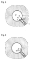
- the hollow profile 5 begins in the trough 11 of the still in Expand the non-use position of the stamp 7 (Fig. 2).
- the plunger 13 becomes its other stop, thus against its slot end 17 against the retaining bolt 14 against shifted the force of the compression spring 20, which in a biased Condition passes.
- the plunger 13 acts as it were as a counterhold, as he did from the formation of T-pieces is known by hydroforming. It forms a bump 22 on the hollow profile 5, while the flow of the hollow profile material into the depression 11 in the edge region 23 the guide hole 6 at the transition to the engraving 4 by pulling the Material is thinned over the guide hole edge.
- the End face 35 of the plunger 13 then forms in its non-use position together with the face 8 of the stamp 7 the reason of the expansion trough 11.
- the stamp 7 is engraved towards the 4 undiminished high internal high pressure by means of a high pressure generating hydraulics acting as drive means shifted until the Ring cutting edge 9 in the hollow profile wall 24 in the form of a piercing cuts.
- the incision leaves a thin area 25 arise in the hollow profile wall 24, at the same time the Bump 22 of the future hole 26 by the stamp movement something in the direction of the interior 27 of the hollow section 5 is pushed back (Fig. 3).
- the creation of the thin point 25 is due to the previous thinning of the hollow profile material supported in the edge area 23 by the expansion of the hollow profile 5, the incision then only with a lower penetration depth must be done as the incision without previous Thinning out.
- the ring cutter 9 is also in terms of their wear and tear somewhat spared.
- the hypertension avoids that when piercing the stamp 7 the Hollow profile wall 24 in the area that to be generated Hole 29 adjoins laterally, bent towards the hollow profile interior 27 and thus the uniform course of the outside 10 of the hollow profile 5 deformed
- the stamp 7 After creating the thin point 25, the stamp 7 is impact or suddenly pulled back into the non-use position, whereupon the thin area 25 tears all around.
- the wall thickness of the Thin point 25 is dimensioned or so unstable that the perforated slug 26 easily by the action alone torn out of the hollow profile wall 24 with the internal high pressure becomes. Because of the clean cut through the ring cutting edge 9 is the wall 28 of the hole 29 created at the end to the outside 10 of the hollow profile 5 flat and sharp-edged. The outside 10 remains until the hole formation constant pressure of the internal high pressure on the engraving 4 undeformed also in the area of the hole wall 28, so that the shape course the hollow profile 5 is maintained after the perforation.
- the jerky retraction of the stamp 7 is advantageous the inertia of the still in the hollow profile wall 24 hole punch 26 and the short time between the outside 10 of the hollow profile 5 and the stamp 7 resulting negative pressure used for tearing, so that by the the pressure difference between the hollow profile interior was increased 27 and that of the outside 10 of the hollow profile 5 and the stamp 7 formed space of the slug 26 also suddenly - without having contact with the stamp 7 - is torn out of the hollow profile wall 24 even more easily.
- the wall 24 of the hollow profile 5 for producing a hole 29 of smaller cross-sectional area is weakened more than in manufacturing a hole 29 of larger cross-sectional area. The definition or the vote is such that the holes 29 arise practically simultaneously.
- the hole slugs are separated 26 do not happen completely, they hang at most still on a thin wall thread 30 (Fig. 4), which later the removal of the perforated hollow profile 5 from the forming tool 1 can be capped.
- the possible result Burr is of low priority for the manufacturing quality of the hollow profile 5 Significance because the ridge is due to the previous one Cutting through the ring edge 9 of the punch 7 is not in the area of the outside 10 of the hollow profile 5.
- the inventive method are simple any hole geometries can be formed, only the stamp 7 on its end face 8 and its guide bore 6 accordingly must be trained.
- the stamp 7 can in the non-use position in such a way Guide hole 6 may be arranged that of the hollow profile wall 24 separate slugs 26 only partially the hollow profile 5 can leave.
- the slug 26 is about 3/10 - 5/10 of the wall thickness of the hollow profile wall 24 still in Hole 29.
- the process of separating the slug 26 from the hollow profile wall 24 is now complete. After that, the internal high pressure preferably within the hollow profile interior 27 lowered to atmospheric pressure, after which the plunger 13 on the Hole slug 26 is moved. This is entirely from the plunger 13 pressed back into the hole 29 so that a protrusion of the Punched hole 26 avoided on the outside 10 of the hollow profile 5 is a removal of the machined hollow profile would hinder or even prevent.
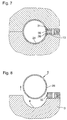
- a stamp 36 can be used be the 8 on its face instead of the ring cutter 9 has an annular wall 31 as penetrant, which is rectangular in cross section and with its outside 32 is flush with the circumference of the stamp, as shown in Fig. 5 can be seen.
- the stamp 36 is already in Position of use, being driven by a high pressure generator Hydraulics - by means of the annular wall 31 in the hollow profile wall 24 has penetrated and through the embossing a forming the thin point 25, according to the shape of the Wall 32 creates circumferential wall weakening.
- the opening takes place here by lifting the upper tool 2, after which the machined Hollow profile 5 can be removed.
- the perforation axis runs thereby in the division surface 21 of the upper and lower tool 2, 3 (Fig. 8). This applies to the creation of several holes 29 First embodiment said in the correspondingly transmitted Senses.
- the plunger 13 can be arranged locally separately from the punch 7 or 36 be and for the exercise of its function in the use position be moved. The same is also conceivable that from the stamp 7 or 36 itself takes over the plunger function becomes. As a result, a component, the plunger 13, and its Drive saved. However, this option is mentioned practicable only when the slug 26 is not in the Has trough 11, 33 of the stamp 7, or 36 jammed. Thus forms the integration of the plunger 13 in the stamp 7 or 36 not only a simple one for pushing back the slug 26 structural solution, but also yields - apart from the better Process economics with respect to the first listed above Possibility - the functional advantage that the plunger 13 in Stamp 7 or 36 pinched perforated slug 26 releases.
- the holes 29 can be produced both in the case of hollow profiles 5, which were made in other tools as well take place with hollow sections 5, which first by hydroforming from a hollow inserted in the forming tool 1 Blank and then calibrated.
- the Hollow section 5 can be made of assembled, preferably welded Half shells or extruded profiles exist.
- the hollow profile 5 after insertion into the forming tool 1 can be expanded by high pressure, which thereby one protruding into the engraving 4 of the forming tool 1 stamp 7 or 36 supported on the back, whereby due to the penetration of the stamp 7, 36 into the hollow profile wall 24 the thin point 25 of the hollow profile wall 24 is trained.
- the Stamp 7, or 36 withdrawn, after which the thin section 25 under Influence of the internal high pressure tears and the resulting one Punch 26 is torn outwards.
- the hole slug 26 is when completely removed from the hollow profile wall 24 into the trough 11 or 33 of the stamp 7 or 36 pressed inside the guide bore 6 and there jammed. When partially removing the slug 26 gives the stamp 7, or 36 through the permanent system on Punch 26 sufficient hold so that this is not an option takes place in an uncontrolled manner in the interior 27 of the hollow profile 5 or to get into the forming tool 1.
- the forming tool is an embodiment at atmospheric pressure 1 opened, after which the hollow profile 5 are removed can.
- the perforated slug can now be used 26 using a simple device conventional from the Hollow profile 5 are pushed out without causing deformation of the hollow profile 5 comes in the edge region of the hole 29.
- the pushing out or the pulling out of the slug 26 can for example in the case of essentially straight lines Hollow sections 5 are of sufficiently large cross section, wherein in a retractable into the hollow profile 5 designed as a lance Device 37 one or more displaceable ejector stamps 38 are arranged, which for this purpose in transverse bores 39 Lance are guided (Fig. 9).
- the ejector stamp 38 communicates its plate-shaped head 40, which with its circumference on the Cross bore wall 41 is sealingly circumferential, the cross bore 39 in two sub-rooms 42, 43.
- the subspace 42 has one Pressure port 44, by means of which the sub-space 42 and thus the head 40 of the ejector stamp 38 with compressed air or one Hydraulic fluid can be applied.
- the ejector stamp 38 When excess pressure is exerted the ejector stamp 38 is counter to the force of a Compression spring 45, which is located in the partial space 43 on the one hand there End wall 46 of the tapered transverse bore 39 and on the other hand on the underside of the head facing away from sub-space 42 47 supports, moved in the direction of the end wall 46.
- a Compression spring 45 which is located in the partial space 43 on the one hand there
- At precise positioning of the lance relative to the hollow profile 5 by moving the stamp shaft 48 with his to Hollow section 5 facing free end 49 on the in the hollow section wall 24 pinched hole slug 26, whereupon another Displacement of the shaft 48 of the perforated slugs 26 from the hollow profile wall 24 is pushed out.
- the transverse bore 39 is open the side of the subspace opposite the stamp head 40 42 sealed from the pressure
- the transverse bore 39 is like a blind hole is formed and that the subspace 42 in the area of the Stamp head 40 opposite end wall of an axially in the pressure channel running through the lance is cut. Will the Pressure relieves, the ejector stamp 38 from the compression spring 45 driven back from the hollow profile 5 into the bore 39.
- the arrangement of the ejector stamp 38 can be any Angular positions may be provided; in addition, several can Ejector stamp 38 parallel to one another or around a defined one Angular position offset from each other in the lance be. It is also conceivable that the lance only one Ejector stamp 38 has. For ejecting several slugs 26 on the same hollow profile 5, the lance must be axial defined to be moved or if the slug is under different angular positions to each other to be turned around.
- the lance is inside the Hollow profile 5 arranged coaxially to this and of this way spaced that they with retracted ejector stamp 38th within the hollow profile 5 for pushing out several in the circumferential direction of the hollow profile 5 at an angle from each other offset holes 26 arranged in holes 29 about their axis can be rotated.
- the hollow profile 5 itself can be clamped are stationary or in a tool shape, the openings at a suitable point for ejecting the slugs 26 owns.
- the perforated slugs can be removed, for example during the testing process of the hollow profiles 5 at the Quality inspection to check the perforations.
- the method according to the invention for removing slugs 26 from the forming tool 1 is in all known, on the action a manufacturing process based on high fluid pressure of holes on hollow profiles applicable.
- both manufacturing processes includes, in which the perforated slugs from the outside to can be separated from the inside of the hollow profile wall, as well Manufacturing processes in which this separation from the inside out done outside.
- the hollow profile itself is from the Surround high pressure liquid.
- a stamp which when a High fluid pressure within the forming tool in the transverse bore will reverse.
- the now forming Opening of the cross hole displaces the hollow profile material into it, whereupon this after exceeding the material stretchability tears in the area of the opening edge of the transverse bore.
- the tearing can be done by forming the opening edge Cutting edge are still supported, including a hole with a smoother hole wall. The resulting slug is pressed back into the hollow profile wall by the punch and jammed there.
- the hydraulic fluid can then drain off the lance with or without a hollow profile is removed from the forming tool will. If it is removed with the hollow profile, then there the position of the lance to the hollow profile remains unchanged, outside of the forming tool by re-loading the respective one Punched hole by means of the extended than when jamming Stamp the perforated slugs in a simple process saving Way out of the hole. Will the lance removed separately from the forming tool, are for removing the Hollow profile and something else to remove the slugs more complex process steps are necessary.
- the perforation can otherwise be done by applying of a punch that is engraved on the outside inserted hollow profile acts. So that the slug due to the pressure drop that occurs during punching, not into the The interior of the hollow profile falls into the hollow profile arranged counterholder is required, which does not yet have the hole completely leaving the slug pressed back into this.
Abstract
Description
Die Erfindung betrifft ein Verfahren zum Herstellen von Löchern
am Umfang eines Hohlprofiles nach dem Oberbegriff des Patentanspruches
1 und eine Einrichtung dazu nach dem Oberbegriff des
Patentanspruches 12.The invention relates to a method for producing holes
on the circumference of a hollow profile according to the preamble of the
Ein gattungsgemaßes Verfahren bzw. eine gattungsgemäße Einrichtung ist aus der US 4,989,482 bekannt. Hierbei wird im Anschluß an einen Umformvorgang mittels Innenhochdruckumformen bei einem Innendruck im Bereich zwischen etwa 7 und 700 bar zur Erzeugung eines Loches im Umfang des im Umformwerkzeuges noch befindlichen Hohlprofiles ein Stempel auf die Hohlprofilwandung von außen geführt, welche dort unter der flächigen Beaufschlagung des Stempels in den Innenraum des Hohlprofiles eingedrückt wird. Der Stempel weist einen Kanal auf, der seine das Hohlprofil beaufschlagende mit einer Mulde versehene Stirnseite mit der Atmosphäre verbindet. Dadurch ergibt sich zwischen der Stirnseite des Stempels im Muldenbereich und dem Hohlprofilinnenraum ein Druckunterschied, der das Hohlprofil an die die Mulde umgebende ringförmige Anlagefläche der Stirnseite des Stempels anpreßt. Bei weiterer Eindrückung der Hohlprofilwandung wird die Dehnfähigkeitsgrenze des Hohlprofilmaterials erreicht, bei deren Übersteigen die Hohlprofilwandung um die Beaufschlagungsstelle des Stempels herum unter Ausbildung eines Lochbutzens reißt. Aufgrund der unebenen Lochwandung des erzeugten Loches ergibt sich jedoch keine ausreichende Abdichtung des beim Eindrücken des Stempels zwischen der Außenseite des Hohlprofiles und der den Stempel führenden Matrize geschaffenen Raumes sowie der Stempelführung der Matrize gegenüber dem Innenraum des fluiddruckbeaufschlagten Innenraumes des Hohlprofiles, so daß trotz der radialen Anlage der Lochwandung am Umfang des Stempels ein Druckabfall innerhalb des Hohlprofiles erfolgt. Dadurch wird die Druckdifferenz zwischen Atmosphäre und dem Hohlprofilinnenraum so gering, daß die Ansaugwirkung des Stempels am Lochbutzen aufgehoben wird, zumindest jedoch in erheblichem Ausmaß verringert wird. In erstem Fall löst sich der Lochbutzen vom Stempel und fällt in den Innenraum des Hohlprofiles hinein. Im zweiten Fall haftet der Lochbutzen mit nur geringer Kraft an der Stirnseite des Stempels an. Bei der Rückzugsbewegung des Stempels gelangt der Lochbutzen wieder in das Loch. Dies gelingt jedoch nur zum Teil, da die zum Hohlprofilinnenraum hin gebogene Lochwandung der durch das Zurückziehen des Stempels erwirkten Rückführbewegung des Lochbutzens Widerstand entgegenbringt, wobei aufgrund der oben erwähnten geringen Ansaugkraft unter Einstellung des Druckausgleiches der Stempel vom Lochbutzen abhebt. In den meisten Fällen fällt der Lochbutzen sogar - ohne Halt an der Lochwandung zu finden - in den Hohlprofilinnenraum hinein. Bleibt andererseits der Lochbutzen im Loch hängen, so ist die Klemmwirkung in diesem klein. Entgegen der in der gattungsbildenden Druckschrift dargelegten Behauptung nach dem Einklemmen des Lochbutzens sei ein Druckaufbau innerhalb des Hohlprofiles möglich, wodurch die umgebogene Lochwandung geebnet wird, was eine zusätzliche Verspannung des Lochbutzens im Loch nach sich zieht, wird sich ein Überdruck schon deswegen nicht aufbauen können, weil keine Formentsprechung der Lochwandung und des Lochbutzens in dessen in den Hohlprofilinnenraum hineinstehenden Verklemmlage vorhanden ist. Damit ist eine gegenüber einem Hochdruck dichtungswirksame Anlage des Lochbutzens an der Lochwandung ausgeschlossen. Aufgrund von bei der Entnahme des Hohlprofiles aus dem Innenhochdruck-Umformwerkzeug auftretenden Vibrationen am Hohlprofil löst sich der Lochbutzen aus seiner instabilen Verklemmlage und fällt in den Hohlprofilinnenraum hinein. Da der Hohlprofilinnenraum trotz abgeflossener Hochdruckflüssigkeit noch einen Naßfilm aufweist, gleitet der Lochbutzen bei der Entnahme des Hohlprofiles aus diesem heraus und in das Umformwerkzeug hinein. Die gesonderte Entnahme des Lochbutzens aus dem Umformwerkzeug ist sehr aufwendig, wobei ein "vergessener" im Umformwerkzeug verbleibender Lochbutzen bei nachfolgenden Umformvorgängen zu irreparablen Beschädigungen des Umformwerkzeuges führt.A generic method or a generic device is known from US 4,989,482. This will follow a forming process using hydroforming at a Internal pressure in the range between about 7 and 700 bar for generation a hole in the circumference of that still in the forming tool Hollow profile a stamp on the hollow profile wall from the outside led, which there under the flat loading of the Stamp is pressed into the interior of the hollow profile. The stamp has a channel which acts on the hollow profile with a recessed face with the atmosphere connects. This results in between the face of the punch in the trough area and the hollow profile interior Pressure difference that the hollow profile to the surrounding the trough presses annular contact surface of the end face of the stamp. When the hollow profile wall is pressed in further, the elastic limit becomes of the hollow profile material reached at their Exceed the hollow profile wall around the point of application of the stamp tears around to form a hole. Because of the uneven hole wall of the hole created however, there is no adequate sealing when pressed in of the stamp between the outside of the hollow profile and the the die-bearing die created space and the Stamp guide of the die opposite the interior of the fluid pressure Interior of the hollow profile, so that despite the radial contact of the hole wall on the circumference of the stamp Pressure drop occurs within the hollow profile. This will the pressure difference between the atmosphere and the hollow profile interior so low that the suction effect of the stamp on the perforated slug is lifted, at least to a considerable extent is reduced. In the first case, the slug detaches from Stamp and falls into the interior of the hollow profile. in the in the second case, the perforated slug adheres with little force the face of the stamp. With the withdrawal movement of the The punch slug gets into the hole again by means of a stamp. This succeeds but only in part, as they face the hollow profile interior curved hole wall of the by withdrawing the stamp provides resistance to the return movement of the slug, due to the low suction force mentioned above with the pressure compensation of the punch from the slug takes off. In most cases, the slug even falls - without finding a hold on the hole wall - in the hollow profile interior inside. On the other hand, if the slug gets stuck in the hole, so the clamping effect in this is small. Contrary to the in according to the statement presented in the generic document the pinching of the hole is a pressure build-up within of the hollow profile possible, whereby the bent hole wall is leveled, resulting in an additional bracing of the perforated slug in the hole, there will be overpressure for that reason alone can not build up, because there is no shape of the hole wall and the slug in the inside of the hollow profile standing jamming position is present. That is one opposite a high-pressure sealing system of the slug excluded on the hole wall. Because of the Removal of the hollow profile from the internal high pressure forming tool Vibrations on the hollow profile release the slug from its unstable jamming position and falls into the hollow profile interior inside. Because the hollow profile interior despite having flowed High pressure liquid still has a wet film, slides the slug when removing the hollow profile from this out and into the forming tool. The separate removal the slug from the forming tool is very complex, with a "forgotten" slug remaining in the forming tool irreparable damage in subsequent forming processes of the forming tool.
Der Erfindung liegt die Aufgabe zugrunde, ein gattungsgemäßes Verfahren bzw. eine gattungsgemäße Einrichtung dahingehend weiterzubilden, daß der beim Lochen erzeugte Lochbutzen in einfacher Weise aus dem Innenhochdruck-Umformwerkzeug entfernt werden kann.The invention has for its object a generic To further develop a method and a generic device, that the perforated slug generated during punching is easier Way removed from the hydroforming tool can.
Die Aufgabe ist erfindungsgemäß durch die Merkmale des Patentanspruches
1 bezüglich des Verfahrens und durch die Merkmale
des Patentanspruches 12 bezüglich der Einrichtung gelöst.The task is according to the invention by the features of the
Dank der Erfindung kann der Lochbrntzen ohne Zuhilfenahme eines fluidischen Innenhochdruckes im vorläufig erzeugten Loch derart verklemmt werden, daß das Hohlprofil dem Innenhochdruck-Umformwerkzeug entnommen werden kann ohne daß dabei der Lochbutzen aus dem Loch herausfällt. Somit entfällt der Aufwand das Umformwerkzeug von Lochbutzen zu säubern. Des weiteren erfordert es keinen Aufbau eines Fluidhochdruckes und den damit zusammen-hängenden apparativen Aufwand, den Lochbutzen in das Loch zurückzudrücken, wobei auf hochdruckfeste Abdichtungen verzichtet werden kann. Aufgrund des fehlenden Überstands des Lochbutzens im Loch über die Außenseite des Hohlprofiles hinaus läßt sich das Hohlprofil auch einfach dem Umformwerkzeug entnehmen. Weiterhin werden die verfahrenstechnischen Schwierigkeiten der Lochbutzenruckführung hinsichtlich eines Druckabfalles nach dem Herstellen des Loches umgangen. Die Herauslösung des verklemmten Lochbutzens erfolgt nach der Entnahme des Hohlprofiles aus dem Umformwerkzeug in einfacher Weise, wobei der Lochbutzen aufgrund der externen Herauslösung keinen Schaden im und/oder Entsorgungsaufwand aus dem Umformwerkzeug anrichten kann. Aufgrund der festen Verklemmung des Lochbutzens ist schließlich ein Lochen unter allen möglichen Winkelstellungen - bezogen auf die Achsenlage des Hohlprofiles innerhalb des Umformwerkzeuges - am Umfang des Hohlprofiles möglich ohne daß die Gefahr besteht, daß nach der Druckentspannung in Folge der Locherzeugung der Lochbutzen in das Hohlprofil oder bei Entnahme des Hohlprofiles und einem bezüglich des Hohlprofiles von innen nach außen vorausgegangenen Lochvorgang in das Umformwerkzeug hineinfällt.Thanks to the invention, the perforated hole can be made without the aid of a fluidic internal high pressure in the preliminarily generated hole in such a way be jammed that the hollow profile the hydroforming tool can be removed without the slug falls out of the hole. This eliminates the expense of the forming tool to clean of slugs. Furthermore requires there is no build-up of a high fluid pressure and the related issues equipment effort to push the slug back into the hole, with no high pressure resistant seals can be. Due to the missing protrusion of the slug in the hole beyond the outside of the hollow profile simply remove the hollow profile from the forming tool. Farther the procedural difficulties of Punch pressure control with regard to a pressure drop after Bypassing the hole. The release of the jammed Punching takes place after the hollow profile has been removed the forming tool in a simple manner, the slug due to the external extraction no damage in and / or Disposal effort from the forming tool can cause. Because of the tight jamming of the slug is finally punching at all possible angular positions - related to the axis position of the hollow profile within the forming tool possible on the circumference of the hollow profile without the risk of that after the pressure release as a result of the hole creation the perforated slug in the hollow profile or when removing the hollow profile and one with respect to the hollow profile from the inside out previous punching process falls into the forming tool.
Zweckmäßige Ausgestaltungen der Erfindung können den Unteransprüchen
entnommen werden; im übrigen ist die Erfindung anhand
zweier in den Zeichnungen dargestellter Ausführungsbeispiele
nachfolgend näher erläutert; dabei zeigt:
In Fig. 1 ist ein zweigeteiltes Innenhochdruck-Umformwerkzeug 1
dargestellt, welches aus einem Oberwerkzeug 2 und einem Unterwerkzeug
3 besteht, die die beiden Hälften des Werkzeuges 1
bilden. Die Teilungsfläche 21 der von Ober- und Unterwerkzeug
2,3 ist horizontal ausgerichtet. In der vom Ober-und Unterwerkzeug
2,3 ausgebildeten Gravur 4 ist ein rohrförmiges Hohlprofil
5 mit kreisrundem Querschnitt eingesetzt. Hierbei sind jedoch
auch andere Querschnittsgeometrien des Hohlprofiles 5 und entsprechende
Formen der Gravur 4 denkbar. Auch kann das Hohlprofil
5 über seine Länge hinweg ein oder mehrfach gebogen sein.1 shows a two-part internal high-
Unter einem Winkel von etwa 45° zur Hohlprofilachse ist in das
Unterwerkzeug 3 eine feinbearbeitete Fuhrungsbohrung 6 eingearbeitet,
die radial zur Gravur 4 ausgerichtet ist und in dieser
ausmündet. In der Führungsbohrung 6 ist ein Schneidestempel 7
verschiebbar geführt. Der Schneidestempel 7 liegt mit nur geringem
Spiel an der Wandung der Führungsbohrung 6 an, wobei
diese und/oder der Stempelumfang zur Verminderung von Verschleiß
und zur Reibungsreduzierung der beiden Reibungspartner
Stempel 7 und Führungsbohrungswandung mit einer Verschleißschutzschicht
versehen sein kann, die die Gleiteigenschaften
des Stempels 7 in der Führungsbohrung 6 erhöht. Die Führungsbohrung
6 kann auch unter anderen Winkeln zur Hohlprofilachse
gelegen und muß nicht zwangsweise radial ausgerichtet sein. Die
radiale Ausrichtung ist jedoch für eine einfache Ausbildung des
Stempels 7 bei einem rohrförmigen Hohlprofil 5 günstig.At an angle of about 45 ° to the hollow profile axis is in the
Der Stempel 7 ist zylindrisch mit kreisrundem Querschnitt ausgebildet.
An seiner der Gravur 4 zugewandten Stirnseite 8 weist
der Stempel 7 eine mit der Außenseite 34 mit dem Umfang des
Stempels 7 fluchtende Ringschneide 9 auf, die in der aus der
Fig. 1 ersichtlichen Nicht-Gebrauchsstellung des Stempels 7 an
der Außenseite 10 des Hohlprofiles 5 durchgängig anliegt und
dabei umlaufend bündig mit der Gravur 4 abschließt. Die Ringschneide
9 begrenzt eine Mulde 11, deren Grund von der Stirnseite
8 gebildet wird. Die Mulde 11 und gleichzeitig auch die
Stirnseite 8 ist von ihrer konkaven Form und Tiefe dahingehend
ausgebildet, daß das später vom Stempel 7 beaufschlagte Wandungsstück
des Hohlprofiles 5 als Lochbutzen 26 nahezu gänzlich
aufgenommen werden kann.The
Der Stempel 7 weist eine axiale Bohrung 12 auf, in der ein
stempelartiger Stößel 13 mit geringem Spiel geführt ist. Der
Stößel 13 ist durch einen Haltebolzen 14 gesichert, der in eine
Querbohrung 15 des Stempels 7 eingepreßt ist. Zur Ermöglichung
einer Verschiebung weist der Stößel 13 ein axial verlaufendes
Langloch 16 auf, dessen Enden 17,18 die Anschläge am Haltebolzen
14 bilden. Der Stößel 13 ist auf rückwärtiger Seite 19 von
einer Druckfeder 20 abgestützt bzw. wird von dieser zur Gravur
4 hin getrieben. Die Abstützung sowie der Antrieb des Stößels
13 kann jedoch auch hydraulisch, pneumatisch oder durch ein
Schieberglied mechanisch erfolgen. Der Stößel 13 liegt ebenfalls
mit seiner Stirnseite 35 in Nicht-Gebrauchslage des Stempels
7 am Hohlprofil 5 an, wobei das Ende 18 des Langloches 16
am Haltebolzen 14 anliegt. In diesem Stadium herrscht im vorzugsweise
metallischen Hohlprofil 5 ein Druck, der geringer ist
als ein Druck, der das Hohlprofil 5 nach außen aufweiten wurde,
bspw. Atmosphärendruck.The
Wird der Druck auf einen Umformdruck von etwa 2000 bar erhöht,
beginnt sich das Hohlprofil 5 in die Mulde 11 des noch immer in
Nicht-Gebrauchsstellung befindlichen Stempels 7 aufzuweiten
(Fig. 2). Dabei wird der Stößel 13 zu seinem anderen Anschlag,
also zur Anlage seines Langlochendes 17 am Haltebolzen 14 gegen
die Kraft der Druckfeder 20 verschoben, welche in einen vorgespannten
Zustand übergeht. Der Stößel 13 wirkt hierbei quasi
als Gegenhalter, wie er auch von der Ausbildung von T-Stücken
durch Innenhochdruck-Umformen her bekannt ist. Es bildet sich
eine Beule 22 am Hohlprofil 5 aus, wobei beim Fließen des Hohlprofilmaterials
in die Mulde 11 hinein dieses im Randbereich 23
der Führungsbohrung 6 am Übergang zur Gravur 4 durch Ziehen des
Materials über den Führungsbohrungsrand ausgedünnt wird. Die
Stirnseite 35 des Stößels 13 bildet dann in seiner Nicht-Gebrauchsstellung
zusammen mit der Stirnseite 8 des Stempels 7
den Grund der Aufweitmulde 11.If the pressure is increased to a forming pressure of approximately 2000 bar,
the
Danach wird der Stempel 7 zur Gravur 4 hin entgegen dem unvermindert
hohen Innenhochdruck mittels einer Hochdruck erzeugende
als Antriebsmittel wirkende Hydraulik verschoben, bis daß die
Ringschneide 9 in die Hohlprofilwandung 24 in Form eines Einstechens
einschneidet. Das Einschneiden läßt eine Dünnstelle 25
in der Hohlprofilwandung 24 entstehen, wobei gleichzeitig die
Beule 22 des zukünftigen Lochbutzens 26 durch die Stempelbewegung
etwas in Richtung des Innenraumes 27 des Hohlprofiles 5
zurückgedrängt wird (Fig. 3). Die Erzeugung der Dünnstelle 25
wird durch das vorhergehende Ausdünnen des Hohlprofilmaterials
im Randbereich 23 durch das Aufweiten des Hohlprofils 5 unterstützt,
wobei das Einschneiden dann mit nur geringerer Eindringtiefe
erfolgen muß als das Einschneiden ohne vorheriges
Ausdünnen. Dabei wird auch die Ringschneide 9 hinsichtlich ihrer
verschleißbedingten Abnutzung etwas geschont. Der Innenhochdruck
vermeidet, daß beim Einstechen des Stempels 7 die
Hohlprofilwandung 24 in dem Bereich, der an das zu erzeugende
Loch 29 seitlich angrenzt, zum Hohlprofilinnenraum 27 hin umgebogen
wird und somit den gleichförmigen Verlauf der Außenseite
10 des Hohlprofiles 5 deformiert. Then the
Nach dem Erzeugen der Dünnstelle 25 wird der Stempel 7 schlag-bzw.
ruckartig in die Nicht-Gebrauchsstellung zurückgezogen,
worauf die Dünnstelle 25 umlaufend reißt. Die Wandstärke der
Dünnstelle 25 ist dabei derart bemessen bzw. derart labil, daß
der Lochbutzen 26 ohne weiteres allein durch die Beaufschlagung
mit dem Innenhochdruck aus der Hohlprofilwandung 24 herausgerissen
wird. Aufgrund des sauberen Schnittes durch die Ringschneide
9 ist die Wandung 28 des erzeugten Loches 29 am Abschluß
zur Außenseite 10 des Hohlprofiles 5 hin eben und
scharfkantig. Die Außenseite 10 bleibt durch den bis zur Lochbildung
stetigen Andruck des Innenhochdruckes an die Gravur 4
auch im Bereich der Lochwandung 28 unverformt, so daß der Formverlauf
des Hohlprofiles 5 nach der Lochung gewahrt bleibt.
Durch das ruckartige Zurückfahren des Stempels 7 wird in vorteilhafterweise
die Massenträgheit des noch in der Hohlprofilwandung
24 befindlichen Lochbutzens 26 und der kurzeitig zwischen
der Außenseite 10 des Hohlprofiles 5 und dem Stempel 7
entstehende Unterdruck zum Reißen ausgenutzt, so daß durch die
dabei erreichte Erhöhung der Druckdifferenz zwischen dem Hohlprofilinnenraum
27 und dem von der Außenseite 10 des Hohlprofiles
5 und dem Stempel 7 gebildete Raum der Lochbutzen 26 ebenfalls
schlagartig - ohne Kontakt zum Stempel 7 zu besitzen -
noch leichter aus der Hohlprofilwandung 24 herausgerissen wird.After creating the
Beim Erzeugen mehrerer Löcher 29 durch Heraustrennen von Lochbutzen
26 von innen nach außen tritt im allgemeinen das bekannte
Problem auf, daß beim Heraustrennen eines ersten Lochbutzens
26 aufgrund der nach außen nicht erreichbaren völligen Abdichtung
gegenüber dem Hochdruck ein starker Druckabfall entsteht,
worauf die Folgelöcher nicht oder nur unzureichend mit unmaßhaltigen
Lochmaßen und Verformungen des Hohlprofiles 5 im Randbereich
des Loches 29 in der Art von plastischen Eindrückungen
erzeugt werden können. Insbesondere tritt dies dann auf, wenn
die zu erzeugenden Löcher 29 von unterschiedlich großer Querschnittsfläche
sind, wobei sich das Loch 29 mit der vergleichsweise
größten Querschnittsfläche als erstes aufgrund der an der
Hohlprofilwandung 24 angreifenden größten Scherkraft des Innenhochdruckes
ausbildet. Um dies zu vermeiden bzw. die für eine
weitere maßhaltige Lochfertigung im Innenhochdruck-Umformwerkzeug
1 schädlichen Folgen zumindest zu vermindern werden nach
der Erfindung in vorteilhafter Weise die Eindringtiefe des
Stempels 7 mit seiner Ringschneide 9 in die Hohlprofilwandung
24 für jedes zu erzeugende Loch 29 individuell festgelegt, so
daß sich für die Erzeugung nach dem Eindringen des Stempels 7
eine auf die Querschnittsfläche des betreffenden Loches 29 abgestimmte
Dünnstelle 25 ausbildet. Die Wandung 24 des Hohlprofils
5 zur Herstellung eines Loches 29 von kleinerer Querschnittsfläche
wird hierbei stärker geschwächt als zur Herstellung
eines Loches 29 größerer Querschnittsfläche. Die Festlegung
bzw. die Abstimmung ist derart ausgebildet, daß die Löcher
29 praktisch gleichzeitig entstehen.When creating
Ist bei bestimmten Löchern 29 die Heraustrennung der Lochbutzen
26 nicht ganz vollständig geschehen, so hängen diese höchstens
noch an einem dünnen Wandungsfaden 30 (Fig. 4), der später nach
der Entnahme des gelochten Hohlprofiles 5 aus dem Umformwerkzeug
1 gekappt werden kann. Der dabei eventuell entstehende
Grat ist für die Fertigungsqualität des Hohlprofiles 5 von niederrangiger
Bedeutung, da sich der Grat aufgrund des vorhergehenden
Einschneidens durch die Ringschneide 9 des Stempels 7
nicht im Bereich der Außenseite 10 des Hohlprofiles 5 befindet.For
Durch das erfindungsgemäße Verfahren sind in einfacher Weise
beliebige Lochgeometrien ausbildbar, wobei lediglich der Stempel
7 an seiner Stirnseite 8 und dessen Führungsbohrung 6 entsprechend
ausgebildet sein müssen.The inventive method are simple
any hole geometries can be formed, only the
Der Stempel 7 kann in Nicht-Gebrauchsstellung derart in der
Führungsbohrung 6 angeordnet sein, daß der von der Hohlprofilwandung
24 getrennte Lochbutzen 26 nur zum Teil das Hohlprofil
5 verlassen kann. Der Lochbutzen 26 befindet sich dabei zu etwa
3/10 - 5/10 der Wandstärke der Hohlprofilwandung 24 noch im
Loch 29. Der Trennungsvorgang der Lochbutzens 26 aus der Hohlprofilwandung
24 ist damit abgeschlossen. Danach wird der Innenhochdruck
innerhalb des Hohlprofilinnenraumes 27 vorzugsweise
auf Atmosphärendruck abgesenkt, wonach der Stößel 13 auf den
Lochbutzen 26 verfahren wird. Dieser wird vom Stößel 13 gänzlich
in das Loch 29 zurückgedrückt, so daß ein Überstand des
Lochbutzens 26 über der Außenseite 10 des Hohlprofiles 5 vermieden
wird, der eine Entnahme des bearbeiteten Hohlprofiles
behindern oder gar verhindern würde. Aufgrund der Materialrückfederung
des gelochten Hohlprofiles 5 an der Lochwandung 28
wird immer sichergestellt, daß der Lochbutzen 26 im Loch 29
festklemmt. Das teilweise Herausdrücken des Lochbutzens 26
durch den Innenhochdruck beim Lochen erleichtert das Wiederhineindrücken
durch den Stößel 13 erheblich, da anderenfalls bei
einer völligen Loslösung des Lochbutzens 26 aus der Hohlprofilwandung
24 infolge der angesprochenen radialen Materialrückfederung
der Lochwandung 28 aufgrund des dann im Vergleich zum
Lochbutzenquerschnitt kleineren Lochquerschnittes ein Herein-drücken
des Lochbutzens 26 in das Loch 29 sehr problematisch
wird. Natürlich ist es auch denkbar, daß der Lochbutzen 26
vollständig aus der Hohlprofilwandung 24 herausgerissen wird
und daß danach der Lochbutzen 26 vom Stößel 13 wieder in das
Loch 29 zurückgedrückt wird. Dies ist jedoch - wie gesagt -
aufgrund der Materialrückfederung im Bereich der Lochwandung 28
schwierig.The
Alternativ zu der Herstellung der Dünnstelle 25 nach den Fig.
1-4 durch die Ringschneide 9 kann ein Prägestempel 36 eingesetzt
werden, der an seiner Stirnseite 8 anstelle der Ringschneide
9 als Eindringmittel eine ringförmige Wandung 31 aufweist,
die im Querschnitt rechteckig ist und mit ihrer Außenseite
32 mit dem Stempelumfang bündig abschließt, wie aus Fig.
5 ersichtlich ist. Hier befindet sich der Stempel 36 schon in
Gebrauchsstellung, wobei er - angetrieben über eine hochdruckerzeugende
Hydraulik - mittels der ringförmigen Wandung 31 in
die Hohlprofilwandung 24 eingedrungen ist und durch die Einprägung
eine die Dünnstelle 25 bildende, entsprechend der Form der
Wandung 32 umlaufende Wandungsschwächung erzeugt. As an alternative to the production of the
Beim Einprägen wird - im Unterschied zum vorhergehenden Ausführungsbeispiel,
bei dem die Hohlprofilwandung 24 durch Einstechen
mittels der Ringschneide 9 unter Ausbildung eines Schnittes
getrennt wird - unter Einfluß des Innenhochdruckes Hohlprofilmaterial
der Hohlprofilwandung 24 verdrängt. Das verdrängte
Hohlprofilmaterial fließt in eine Mulde 33 hinein, die in der
Stirnseite 8 des Stempels 36 ausgebildet ist und die von der
ringförmigen Wandung 31 begrenzt wird. Die Mulde 33 wird im Gegensatz
zur Mulde 11 vollständig vom fließenden Hohlprofilmaterial
ausgefüllt. Dieser gezielte Materialabfluß in eine dafür
vorgesehene Mulde 33 hinein ermöglicht erst die Ausbildung der
gewünschten Dünnstelle 25. Mit einer ebenen tellerförmigen Ausbildung
der Stempelstirnseite 8, wie sie aus der gattungsbildenden
Schrift zu entnehmen ist, ist dies nicht möglich.When embossing - in contrast to the previous embodiment,
in which the
In Übereinstimmung mit dem ersten Ausführungsbeispiel wirkt
beim Einprägen der Dünnstelle 25 im Innenraum 27 des Hohlprofiles
5 ein Hochdruck im Bereich von etwa 2000 bar. Ebenfalls bei
diesem Druck erfolgt vor dem Einprägen ein Aufweiten des Hohlprofiles
5, das sich hier in die Mulde 33 hinein aufweitet.
Nach dem Einprägen wird der Stempel 36 in gleicher Weise zurückgezogen,
worauf die Dünnstelle 25 umlaufend reißt (Fig. 6)
und der Lochbutzen 26 vom Innenhochdruck herausgepreßt wird.
Der Stößel 13 drückt bei vorzugsweise Atmosphärendruck den erzeugten
noch mit einem schmalen Umfangsabschnitt im Loch 29
verbleibenden Lochbutzen 26 in das Loch 29 zurück (Fig. 7).
Nach der Verklemmung des Lochbutzens 26 im Loch 29 wird der
Druck im Innenraum 27 des Hohlprofiles 5 völlig entspannt und
dann das Umformwerkzeug 1 geöffnet. Die Öffnung erfolgt hier
durch Anheben des Oberwerkzeuges 2, wonach das bearbeitete
Hohlprofil 5 entnommen werden kann. Die Lochungsachse verläuft
dabei in der Teilungsfläche 21 von Ober- und Unterwerkzeug 2,3
(Fig. 8). Für die Erzeugung mehrerer Löcher 29 gilt das beim
ersten Ausführungsbeispiel Gesagte im entsprechend übertragenen
Sinne. Works in accordance with the first embodiment
when impressing the
Der Stößel 13 kann örtlich separat zum Stempel 7, bzw. 36 angeordnet
sein und für die Ausübung seiner Funktion in die Gebrauchsstellung
verschoben werden. Desgleichen ist auch denkbar,
daß vom Stempel 7, bzw. 36 selbst die Stößelfunktion übernommen
wird. Dadurch wird ein Bauteil, der Stößel 13, und dessen
Antrieb eingespart. Diese genannte Möglichkeit ist jedoch
nur dann praktikabel, wenn der Lochbutzen 26 sich nicht in der
Mulde 11, 33 des Stempels 7, bzw. 36 verklemmt hat. Somit bildet
die Integrierung des Stößels 13 in den Stempel 7, bzw. 36
zum Zurüchdrücken des Lochbutzens 26 nicht nur eine einfache
bauliche Lösung, sondern erbringt auch - abgesehen von der besseren
Verfahrensökonomie bezüglich der ersten oben angeführten
Möglichkeit - den funktionellen Vorteil, daß der Stößel 13 im
Stempel 7, bzw. 36 eingeklemmte Lochbutzen 26 löst.The
Das Erzeugen der Löcher 29 kann sowohl bei Hohlprofilen 5 erfolgen,
die in anderen Werkzeugen hergestellt wurden, als auch
bei Hohlprofilen 5 stattfinden, die zuerst durch Innenhochdruck-Umformen
aus einem im Umformwerkzeug 1 eingebrachten hohlen
Rohling hergestellt und anschließend kalibriert werden. Das
Hohlprofil 5 kann aus zusammengefügten, vorzugsweisen geschweißten
Halbschalen oder auch Strangpreßprofilen bestehen.The
Im übrigen kann alternativ zu den beiden vorherigen Ausführungsbeispielen
das Hohlprofil 5 nach Einlegen in das Umformwerkzeug
1 durch Innenhochdruck aufgeweitet werden, welches dabei
einen in die Gravur 4 des Umformwerkzeuges 1 hineinstehenden
rückwärtig abgestützten Stempel 7, bzw. 36 beaufschlagt,
wodurch infolge des Eindringens des Stempels 7, 36 in die Hohlprofilwandung
24 die Dünnstelle 25 der Hohlprofilwandung 24
ausgebildet wird. Nach abgeschlossener Aufweitung wird der
Stempel 7, bzw. 36 zurückgezogen, wonach die Dünnstelle 25 unter
Einwirkung des Innenhochdruckes reißt und der entstehende
Lochbutzen 26 nach außen gerissen wird.Otherwise, can alternatively to the two previous embodiments
the
Der Lochbutzen 26 wird bei völliger Herauslösung aus der Hohlprofilwandung
24 in die Mulde 11, bzw. 33 des Stempels 7, bzw.
36 innerhalb dessen Führungsbohrung 6 hineingedrückt und dort
verklemmt. Bei der teilweisen Herauslösung des Lochbutzens 26
gibt der Stempel 7, bzw. 36 durch die permanente Anlage am
Lochbutzen 26 ausreichend Halt, so daß dieser keine Möglichkeit
findet unkontrolliert in den Innenraum 27 des Hohlprofiles 5
oder in das Umformwerkzeug 1 hineinzugelangen.The
In allen gezeigten Ausführungsbeispielen wird aufgrund des Einprägens
bzw. des Einschneidens der Hohlprofilwandung 24 nach
dem vom Innenhochdruck verursachten Reißen der gebildeten Dünn-stelle
25 eine im wesentlich einheitlich glatte Lochwandung 28
ausgebildet. Dies erleichtert aufgrund des fehlenden Widerstandes
von makroskopischen Rauhigkeiten das Hineindrücken des
Lochbutzens 26 in das Loch 29. Abgesehen davon ist schon allein
die Bildung einer Sollbruchstelle von großem Nutzen, da somit
der Lochbutzen 26 örtlich definiert reißt, so daß es zu keiner
unerwünschten Rißbildung des Hohlprofilmaterials seitlich der
Öffnung der Führungsbohrung 6 kommt, die darüber hinaus auch
noch unkontrolliert verläuft. Der entstehende mit starken Randverformungen
versehene Lochbutzen 26 wäre dabei durch das nachträgliche
Zurückdrücken mittels des Stößels 13 nur sehr schwer
in der Scharten aufweisenden, völlig rauhen Lochwandung 28 zu
verklemmen.In all of the exemplary embodiments shown, due to the embossing
or the cutting of the
Nach dem vorläufigen Erzeugen der Löcher 29 gemäß der obigen
Ausführungsbeispiele wird bei Atmosphärendruck das Umformwerkzeug
1 geöffnet, wonach das Hohlprofil 5 diesem entnommen werden
kann. Nach der Hohlprofilentnahme kann nun der Lochbutzen
26 mit Hilfe einer einfachen Vorrichtung konventionell aus dem
Hohlprofil 5 herausgedrückt werden, ohne daß es zu Verformungen
des Hohlprofiles 5 im Randbereich des Loches 29 kommt.After provisionally creating
Das Herausdrücken bzw. das Herauslösen des Lochbutzens 26 kann
beispielsweise bei im wesentlichen geradlinig verlaufenden
Hohlprofilen 5 ausreichend großen Querschnittes erfolgen, wobei
in einer in das Hohlprofil 5 einschiebbaren als Lanze ausgebildeten
Vorrichtung 37 ein oder mehrere verschiebbare Auswerferstempel
38 angeordnet sind, die dazu in Querbohrungen 39 der
Lanze geführt sind (Fig. 9). Der Auswerferstempel 38 teilt mit
seinem tellerförmigen Kopf 40, der mit seinem Umfang an der
Querbohrungswandung 41 dichtend umlaufend anliegt, die Querbohrung
39 in zwei Teilräume 42,43. Der Teilraum 42 weist einen
Druckanschluß 44 auf, mittels dessen der Teilraum 42 und damit
der Kopf 40 des Auswerferstempels 38 mit Druckluft oder einer
Druckflüssigkeit beaufschlagbar ist. Bei Ausüben eines Überdruckes
wird der Auswerferstempel 38 entgegen der Kraft einer
Druckfeder 45, die sich im Teilraum 43 einerseits an der dortigen
Stirnwand 46 der sich stufig verjüngenden Querbohrung 39
und andererseits an der vom Teilraum 42 abgewandten Kopfunterseite
47 abstützt, in Richtung der Stirnwand 46 verschoben. Bei
genauer Positionierung der Lanze gegenüber dem Hohlprofil 5 gelangt
durch das Verschieben der Stempelschaft 48 mit seinem zum
Hohlprofil 5 weisenden freien Ende 49 auf den in der Hohlprofilwandung
24 eingeklemmten Lochbutzen 26, worauf bei weiterer
Verschiebung des Schaftes 48 der Lochbutzen 26 aus der Hohlprofilwandung
24 herausgedrückt wird. Die Querbohrung 39 ist auf
der dem Stempelkopf 40 gegenüberliegenden Seite des Teilraumes
42 vom dort befestigten Druckanschluß 44 dichtend verschlossen.
Denkbar ist jedoch auch, daß die Querbohrung 39 sacklochartig
ausgebildet ist und daß der Teilraum 42 im Bereich der dem
Stempelkopf 40 gegenüberliegenden Stirnwand von einem axial in
der Lanze verlaufenden Druckkanal angeschnitten ist. Wird der
Druck entspannt, wird der Auswerferstempel 38 von der Druckfeder
45 vom Hohlprofil 5 weg in die Bohrung 39 zurückgetrieben.The pushing out or the pulling out of the
Die Anordnung des Auswerferstempels 38 kann unter beliebigen
Winkelstellungen vorgesehen sein; außerdem können auch mehrere
Auswerferstempel 38 parallel zueinander oder um eine definierte
Winkelstellung voneinander versetzt in der Lanze vorhanden
sein. Ebenfalls ist es denkbar, daß die Lanze nur einen einzigen
Auswerferstempel 38 aufweist. Zum Ausstoßen mehrerer Lochbutzen
26 am gleichen Hohlprofil 5 muß die Lanze jeweils axial
definiert verschoben werden oder, wenn sich die Lochbutzen unter
unterschiedlichen Winkelstellungen zueinander befinden, definiert
gedreht werden. Hierzu ist die Lanze innerhalb des
Hohlprofiles 5 zu diesem koaxial angeordnet und von diesem derart
beabstandet, daß sie mit eingefahrenem Auswerferstempel 38
innerhalb des Hohlprofiles 5 zum Herausdrücken mehrerer in Umfangsrichtung
des Hohlprofiles 5 unter einem Winkel voneinander
versetzt in Löchern 29 angeordneter Lochbutzen 26 um ihre Achse
gedreht werden kann. Das Hohlprofil 5 selbst kann in einer Einspannung
ortsfest sich befinden oder in einer Werkzeugform liegen,
die an geeigneter Stelle Durchbrüche zum Ausstoß der Lochbutzen
26 besitzt. Das Herauslösen der Lochbutzen kann beispielsweise
während des Prüfvorgangs der Hohlprofile 5 bei der
Qualitätsprüfung zur Kontrolle der Lochungen erfolgen.The arrangement of the
Insbesondere bei gebogenen Hohlprofilen 5 und Hohlprofilen 5
kleinen Querschnittes, bei denen derartige Vorrichtungen nicht
einschiebbar sind, sowie bei allen anderen Ausbildungen eines
Hohlprofiles 5 ist es denkbar, die Lochbutzen 26 nach der Hohlprofilentnahme
in den Hohlprofilinnenraum 27 zu drücken und
dann die Lochbutzen 26 aus diesem durch Herausspülen mittels
einer Spülflüssigkeit zu entfernen. Durch die Anordnung des
Stempels 7 bzw. 36 relativ zur Lage des Hohlprofiles 5 innerhalb
des Umformwerkzeuges 1 und durch die Zurückdrängfunktion
des Stößels 13 für den Lochbutzen 26 kann in einfacher Weise
vermieden werden, daß einer oder mehrere undefiniert im Umformwerkzeug
1 oder im Hohlprofil 5 liegende Lochbutzen 26 mit großem
Aufwand aus dem Umformwerkzeug 1 entfernt werden müssen.
Eine leicht handhabbare Entfernung der Lochbutzen 26 bildet für
eine störungsfreie, verfahrensökonomische Automatisierung der
Fertigung gelochter Hohlprofile 5 eine grundlegende Voraussetzung.In particular in the case of curved
Das erfindungsgemäße Verfahren zur Entfernung von Lochbutzen 26
aus dem Umformwerkzeug 1 ist bei allen bekannten, auf der Einwirkung
eines Fluidhochdruckes basierenden Herstellverfahren
von Löchern an Hohlprofilen anwendbar. Hierbei sind sowohl Herstellverfahren
umfaßt, bei denen die Lochbutzen von außen nach
innen aus der Hohlprofilwandung herausgetrennt werden, als auch
Herstellungsverfahren, bei denen diese Trennung von innen nach
außen erfolgt.The method according to the invention for removing
Bei der Lochung von außen nach innen kann beispielsweise in das Hohlprofil eine Lanze eingeführt sein, die am Hohlprofil in einer Preßpassung anliegt. Das Hohlprofil selbst wird von der Hochdruckflüssigkeit umgeben. In der Lanze ist in einer radialen Querbohrung ein Stempel geführt, der bei Anliegen eines Fluidhochdruckes innerhalb des Umformwerkzeuges in die Querbohrung zurückverfahren wird. Dabei wird an der sich nun bildenden Öffnung der Querbohrung das Hohlprofilmaterial in diese hineinverdrängt, worauf dieses nach Übersteigen der Materialdehnfähigkeit im Bereich des Öffnungsrandes der Querbohrung reißt. Das Reißen kann durch die Ausbildung des Öffnungsrand als Schneidkante noch unterstützt werden, wobei sich auch ein Loch mit einer glatteren Lochwandung ergibt. Der entstehende Lochbutzen wird vom Stempel in die Hohlprofilwandung zurückgedrückt und dort verklemmt. Abfließen der Druckflüssigkeit kann dann die Lanze mit oder ohne Hohlprofil dem Umformwerkzeug entnommen werden. Wird sie mit dem Hohlprofil entnommen, kann dann, da die Lage der Lanze zum Hohlprofil unverändert bleibt, außerhalb des Umformwerkzeuges durch erneutes Beaufschlagen des jeweiligen Lochbutzens mittels des weiter als beim Verklemmen ausgefahrenen Stempels der Lochbutzen in einfacher arbeitsgangsparender Weise aus dem Loch herausgedrückt werden. Wird die Lanze separat aus dem Umformwerkzeug entnommen, sind zur Entnahme des Hohlprofiles und zum Herauslösen der Lochbutzen weitere etwas aufwendigere Verfahrensschritte notwendig. Wird der Lochbutzen unter einem Winkel zwischen 0 und 180° bezüglich einer horizontalen mittig verlaufenden Teilungsebene des Hohlprofiles erzeugt, ist es denkbar, daß der Lochbutzen nicht in der Hohlprofilwandung verklemmt werden muß. Dadurch, daß der Lochbutzen innerhalb dieses Winkelbereiches nicht in das Umformwerkzeug fallen kann, verbleibt der Lochbutzen in der Lanze und kann mit dieser nach Druckabbau im Umformwerkzeug und Ableitung der Druckflüssigkeit kontrolliert ohne weiteres aus dem Umformwerkzeug entnommen werden. When punching from the outside in, for example, in the A lance can be inserted into the hollow profile Press fit is present. The hollow profile itself is from the Surround high pressure liquid. In the lance is in a radial Cross bore a stamp, which when a High fluid pressure within the forming tool in the transverse bore will reverse. In doing so, the now forming Opening of the cross hole displaces the hollow profile material into it, whereupon this after exceeding the material stretchability tears in the area of the opening edge of the transverse bore. The tearing can be done by forming the opening edge Cutting edge are still supported, including a hole with a smoother hole wall. The resulting slug is pressed back into the hollow profile wall by the punch and jammed there. The hydraulic fluid can then drain off the lance with or without a hollow profile is removed from the forming tool will. If it is removed with the hollow profile, then there the position of the lance to the hollow profile remains unchanged, outside of the forming tool by re-loading the respective one Punched hole by means of the extended than when jamming Stamp the perforated slugs in a simple process saving Way out of the hole. Will the lance removed separately from the forming tool, are for removing the Hollow profile and something else to remove the slugs more complex process steps are necessary. Will the hole slug at an angle between 0 and 180 ° with respect to a horizontal creates a central dividing plane of the hollow profile, it is conceivable that the perforated slug is not in the hollow profile wall must be jammed. By the fact that the slug not into the forming tool within this angular range can fall, the slug remains in the lance and can with this after pressure reduction in the forming tool and derivation of the Hydraulic fluid is easily checked from the forming tool be removed.
Die Lochung kann anderweitig auch durch Beaufschlagung mittels eines Stanzstempels, der von außen auf das in die Gravur eingelegte Hohlprofil einwirkt, erfolgen. Damit der Lochbutzen aufgrund des beim Lochen entstehenden Druckabfall nicht in den Innenraum des Hohlprofiles hineinfällt, ist ein im Hohlprofil angeordneter Gegenhalter vonnöten, der den das Loch noch nicht völlig verlassenden Lochbutzen wieder in dieses zurückpreßt.The perforation can otherwise be done by applying of a punch that is engraved on the outside inserted hollow profile acts. So that the slug due to the pressure drop that occurs during punching, not into the The interior of the hollow profile falls into the hollow profile arranged counterholder is required, which does not yet have the hole completely leaving the slug pressed back into this.
Claims (20)
dadurch gekennzeichnet,
daß das Verklemmen des herausgetrennten Lochbutzens (26) bei hinsichtlich eines fluidischen Innenhochdruckes entspanntem Fluidhochdruck und verliersicher mittels eines Stempels (7,36) erfolgt, und daß der Lochbutzen (26) nach Entnahme des bearbeiteten Hohlprofiles (5) aus dem Innenhochdruck-Umformwerkzeug (1) aus dem Hohlprofil (5) unter endgültiger Freigabe des Loches (29) herausgelöst wird.Method for producing holes on the circumference of a hollow profile, wherein a wall piece as a slug is separated from the hollow profile within an internal high-pressure forming tool and subsequently clamped there without any protrusion in the provisionally produced hole with respect to the outer circumference of the hollow profile,
characterized,
that the pinching of the perforated slug (26) which has been removed takes place when the high fluid pressure is relaxed with respect to a fluidic internal high pressure and is captive by means of a stamp (7, 36), and that the perforated slug (26) after removal of the machined hollow profile (5) from the internal high pressure forming tool (1 ) is released from the hollow profile (5) with final clearance of the hole (29).
dadurch gekennzeichnet,
daß beim Heraustrennen aus der Hohlprofilwandung (24) der Lochbutzen (26) nur teilweise aus dieser herausgedrückt wird.Method according to claim 1,
characterized,
that when it is separated from the hollow profile wall (24) the perforated slug (26) is only partially pushed out of it.
dadurch gekennzeichnet,
daß das Heraustrennen des Lochbutzens (26) bezüglich des Hohlprofiles (5) von innen nach außen erfolgt und daß dieser zum verliersicheren Verklemmen vom Stempel (7,36) von außerhalb des Hohlprofiles (5) in das Loch hineingedrückt wird. Method according to claim 1,
characterized,
that the perforated slug (26) is separated from the inside with respect to the hollow profile (5) and that this is pressed into the hole from outside of the hollow profile (5) for captive jamming by the punch (7,36).
dadurch gekennzeichnet,
daß das Heraustrennen des Lochbutzens (26) bezüglich des Hohlprofiles (5) von außen nach innen erfolgt und daß dieser zum verliersicheren Verklemmen vom Stempel (7,36) von innerhalb des Hohlprofiles (5) in das Loch (29) hineingedrückt wird.Method according to claim 1,
characterized,
that the perforated slug (26) is separated from the outside with respect to the hollow profile (5) and that it is pressed into the hole (29) from inside the hollow profile (5) for captive jamming by the punch (7, 36).
dadurch gekennzeichnet,
daß das Heraustrennen des Lochbutzens (26) allein durch einen Innenhochdruck erfolgt, der in seiner Höhe im Bereich des Umformdruckes bei einer Innenhochdruck-Umformung des Hohlprofiles (5) gelegen ist.Method according to claim 1,
characterized,
that the perforated slug (26) is cut out solely by means of an internal high pressure, the height of which is in the region of the forming pressure in the case of internal high pressure forming of the hollow profile (5).
dadurch gekennzeichnet,
daß das Heraustrennen des Lochbutzens (26) an einer das spätere Loch (29) umlaufend begrenzenden Sollbruchstelle in der Hohlprofilwandung (24) erfolgt.Method according to claim 5,
characterized,
that the perforated slug (26) is separated out at a predetermined breaking point in the hollow profile wall (24) which circumscribes the later hole (29).
dadurch gekennzeichnet,
daß die Sollbruchstelle in Form einer Dünnstelle (25) durch Einprägen mittels eines Stempels (36) gebildet wird.Method according to claim 6,
characterized,
that the predetermined breaking point in the form of a thin point (25) is formed by embossing by means of a stamp (36).
dadurch gekennzeichnet,
daß die Sollbruchstelle in Form einer Dünnstelle (25) durch Einschneiden mittels eines Stempels (7) gebildet wird.Method according to claim 6,
characterized,
that the predetermined breaking point in the form of a thin point (25) is formed by cutting in by means of a stamp (7).
dadurch gekennzeichnet,
daß das Herauslösen des Lochbutzens (26) nach der Entnahme des bearbeiteten Hohlprofiles (5) aus dem Innenhochdruck-Werkzeug (1) durch Eindrücken des Lochbutzens (26) in den Innenraum (27) des Hohlprofiles (5) hinein und durch anschließendes Herausspulen des Butzens (26) aus dem Innenraum (27) heraus mittels einer Spülflüssigkeit erfolgt.Method according to claim 1,
characterized,
that the removal of the perforated slug (26) after removal of the machined hollow profile (5) from the internal high-pressure tool (1) by pressing the perforated slug (26) into the interior (27) of the hollow profile (5) and then winding the slug out (26) from the interior (27) by means of a rinsing liquid.
dadurch gekennzeichnet,
daß das Herauslösen des Lochbutzens (26) nach der Entnahme des bearbeiteten Hohlprofiles (5) aus dem Innenhochdruck-Werkzeug (1) durch Herausdrücken des Lochbutzens (26) aus dem Hohlprofil (5) erfolgt.Method according to claim 1,
characterized,
that the removal of the perforated slug (26) after removal of the machined hollow profile (5) from the internal high-pressure tool (1) by pressing out the perforated slug (26) from the hollow profile (5).
daß der Lochbutzen (26) bis auf einen dünnen Hohlprofilmaterialfaden herausgetrennt wird und daß im Anschluß an die Hohlprofilentnahme aus dem Umformwerkzeug (1) nach Herauslösen des Lochbutzens (26) aus dem Loch (29) der Materialfaden abgeschert wird.Method according to claim 1,
that the perforated slug (26) is separated apart from a thin hollow profile material thread and that after the hollow profile has been removed from the forming tool (1) after the perforated slug (26) has been removed from the hole (29), the material thread is sheared off.
dadurch gekennzeichnet,
daß das Rückführmittel ein Stempel (7,36,13) ist, mit dem der Lochbutzen (26) verliersicher bei gegenüber einem zum Innenhochdruckumformen verwandten Innenhochdruck entspanntem Druckzustand innerhalb des Hohlprofiles (5) in das vorläufig erzeugte Loch (29) eindrückbar ist, und daß die Einrichtung eine Vorrichtung (37) zum Herauslösen des Lochbutzens (26) nach Entnahme des bearbeiteten Hohlprofiles (5) aus dem Innenhochdruck-Umformwerkzeug (1) beinhaltet, durch die das Loch (29) endgültig erzeugbar ist. Device for producing holes on the circumference of a hollow profile, with a punch integrated in an internal high-pressure forming tool, by means of which a wall piece can be removed as a slug from the hollow profile with provisional creation of a hole, and with a return means, by means of which the cut-out slug can be clamped in the hole is then clamped there without protrusion in the provisionally produced hole with respect to the outer circumference of the hollow profile, for carrying out the method according to claim 1,
characterized,
that the return means is a stamp (7, 36, 13) with which the perforated slug (26) can be pressed captively into the preliminarily produced hole (29) in a pressure state within the hollow profile (5) that is relaxed compared to an internal high pressure used for internal high pressure forming, and that the device includes a device (37) for removing the slug (26) after removal of the machined hollow profile (5) from the internal high-pressure forming tool (1), through which the hole (29) can be finally created.
dadurch gekennzeichnet,
daß ein zur Erzeugung des Loches (29) verwandter Stempel (7,36) das Rückführmittel bildet.Device according to claim 12,
characterized,
that a stamp (7, 36) used to create the hole (29) forms the return means.
dadurch gekennzeichnet,
daß ein in einen zur Locherzeugung verwandten Stempel (7,36) als Stößel (13) ausgebildeter Stempel integriert ist, der das Rückführmittel bildet, wobei der Stößel im Stempel (7,36) verschiebbar geführt ist.Device according to claim 12,
characterized,
that a stamp designed as a plunger (13) is integrated into a stamp (7, 36) used for hole production, which forms the return means, the plunger being displaceably guided in the stamp (7, 36).
dadurch gekennzeichnet,
daß der Stempel (7,36,13) außerhalb des Hohlprofiles (5) in das Umformwerkzeug (1) integriert angeordnet ist.Device according to claim 12,
characterized,
that the stamp (7,36,13) is arranged outside the hollow profile (5) integrated in the forming tool (1).
dadurch gekennzeichnet,
daß der Stempel (7,36,13) in einer in das Hohlprofil (5) einschiebbaren Lanze radial verschiebbar angeordnet ist.Device according to claim 12,
characterized,
that the punch (7,36,13) is arranged radially displaceably in a lance that can be inserted into the hollow profile (5).
dadurch gekennzeichnet,
daß die Einrichtung ein Antriebsmittel aufweist, mittels dessen der Stempel (7,36,13) verschiebbar ist.Device according to claim 12,
characterized,
that the device has a drive means by means of which the stamp (7,36,13) is displaceable.
dadurch gekennzeichnet,
daß die Vorrichtung (37) als Lanze ausgebildet ist, die in das Hohlprofil (5) einführbar ist und die zumindest einen verschiebbaren Auswerferstempel (38) aufweist, mittels dessen der jeweilige Lochbutzen (26) vom Innenraum (27) des Hohlprofiles (5) aus beaufschlagbar ist. Device according to claim 12,
characterized,
that the device (37) is designed as a lance which can be inserted into the hollow profile (5) and which has at least one displaceable ejector stamp (38) by means of which the respective perforated slug (26) from the interior (27) of the hollow profile (5) is acted upon.
dadurch gekennzeichnet,
daß die Lanze derart innerhalb des Hohlprofiles (5) von diesem beabstandet angeordnet ist, daß sie im Nicht-Gebrauchszustand des Auswerferstempels (38) drehbar ist.Device according to claim 18,
characterized,
that the lance is arranged within the hollow profile (5) so that it can be rotated when the ejector plunger (38) is not in use.
dadurch gekennzeichnet,
daß der Auswerferstempel (38) in einer Querbohrung (39) der Lanze angeordnet ist und einerseits - zum Hohlprofil (5) hin - hydraulisch oder pneumatisch antreibbar ist und andererseits von einer rückstellenden Druckfeder (45) abgestützt ist.Device according to claim 18,
characterized,
that the ejector punch (38) is arranged in a transverse bore (39) of the lance and on the one hand - can be driven hydraulically or pneumatically - towards the hollow profile (5) and on the other hand is supported by a restoring compression spring (45).
Applications Claiming Priority (2)
| Application Number | Priority Date | Filing Date | Title |
|---|---|---|---|
| DE19647962 | 1996-11-20 | ||
| DE19647962A DE19647962C1 (en) | 1996-11-20 | 1996-11-20 | Method and device for producing holes on the circumference of a hollow profile |
Publications (2)
| Publication Number | Publication Date |
|---|---|
| EP0844034A2 true EP0844034A2 (en) | 1998-05-27 |
| EP0844034A3 EP0844034A3 (en) | 1998-06-03 |
Family
ID=7812202
Family Applications (1)
| Application Number | Title | Priority Date | Filing Date |
|---|---|---|---|
| EP97118614A Withdrawn EP0844034A3 (en) | 1996-11-20 | 1997-10-27 | Method of and device for manufacturing holes on the periphery of a hollow profile |
Country Status (3)
| Country | Link |
|---|---|
| US (1) | US5996455A (en) |
| EP (1) | EP0844034A3 (en) |
| DE (1) | DE19647962C1 (en) |
Cited By (1)
| Publication number | Priority date | Publication date | Assignee | Title |
|---|---|---|---|---|
| WO2004043623A1 (en) * | 2002-11-12 | 2004-05-27 | Cosma International | Method of forming hydroformed member with opening |
Families Citing this family (18)
| Publication number | Priority date | Publication date | Assignee | Title |
|---|---|---|---|---|
| DE19647963C2 (en) * | 1996-11-20 | 1998-11-26 | Daimler Benz Ag | Method and device for producing holes on the circumference of hollow profiles |
| DE19733473C2 (en) * | 1997-08-02 | 2000-07-06 | Daimler Chrysler Ag | Method and device for producing a connection of a lambda probe holder to an exhaust pipe |
| US6574849B1 (en) * | 1998-08-17 | 2003-06-10 | Siempelkamp Pressen Systeme Gmbh & Co. | Method for deforming through high inner pressure at least two hollow bodies having each at least one opening, especially metal tubes or metal hollow profiles |
| DE19902634A1 (en) * | 1998-10-23 | 2000-04-27 | Alusuisse Lonza Services Ag | Method for removing a slug or the like Waste piece from a work piece, and device therefor |
| DE19859925C2 (en) * | 1998-12-23 | 2002-12-05 | Forschungsges Umformtechnik | Method and device for removing slugs |
| DE19939512A1 (en) * | 1999-08-20 | 2001-02-22 | Schuler Hydroforming Gmbh & Co | Fastening device in a tool for hydroforming |
| AU2001233534A1 (en) * | 2000-02-22 | 2001-09-03 | Cosma International Inc. | Hydroforming flush system |
| DE10016208C1 (en) * | 2000-03-31 | 2001-10-04 | Schuler Hydroforming Gmbh & Co | Cutting section from hollow component during high internal pressure deformation process, employs plunger spring-loaded to snap back abruptly |
| US6305201B1 (en) * | 2001-04-09 | 2001-10-23 | General Motors Corporation | Method and apparatus for forming unobstructed holes in hollow hydroformed metal parts |
| US6401507B1 (en) * | 2001-11-30 | 2002-06-11 | General Motors Corporation | Hydroforming, in-die hydropiercing and slug-ejecting method and apparatus |
| DE10349879B3 (en) * | 2003-10-25 | 2004-08-26 | Daimlerchrysler Ag | Separating process for hollow body involves moving at least one tool part relative to other and to hollow body along body |
| DE10350152B3 (en) * | 2003-10-28 | 2004-10-21 | Daimlerchrysler Ag | Production of a hollow body comprises shaping a hollow body blank in a forming tool using an internal high pressure forming process to produce the hollow body, and cutting a hole and a bracket out of a wall of the hollow body |
| US7104099B1 (en) * | 2005-08-16 | 2006-09-12 | Gm Global Technology Operations, Inc. | Center support punch assembly for hydroforming die |
| US7159426B1 (en) * | 2005-09-27 | 2007-01-09 | Gm Global Technology Operations, Inc. | Quick change assembly for hydroforming punches |
| DE102005061732B4 (en) * | 2005-12-21 | 2015-01-08 | Phoenix Contact Gmbh & Co. Kg | Method of forming a structure on a clamp body for a screw clamp |
| US7360384B1 (en) * | 2007-03-23 | 2008-04-22 | Gm Global Technology Operations, Inc. | Apparatus and method for hydroshearing and hydrotrimming for hydroforming die |
| KR20160032253A (en) * | 2009-08-05 | 2016-03-23 | 지아이. 디아이. 메카니카 에스.피.에이. | A method for obtaining an opening in a hollow-body member, and a hollow-body member provided with one or more openings obtained with said method |
| DE102013003118B4 (en) * | 2013-02-25 | 2015-03-26 | Jenoptik Automatisierungstechnik Gmbh | A method for disposing of a Bußens incurred in a perforation process of a hollow section |
Citations (1)
| Publication number | Priority date | Publication date | Assignee | Title |
|---|---|---|---|---|
| US4989482A (en) * | 1989-11-17 | 1991-02-05 | Ti Corporate Services Limited | Method and apparatus for punching a hole in sheet material |
Family Cites Families (15)
| Publication number | Priority date | Publication date | Assignee | Title |
|---|---|---|---|---|
| AT199463B (en) * | 1956-01-10 | 1958-09-10 | Kovotechna Praha Narodni Podni | Device for punching out small spaced holes in thin hard steel sheets |
| US3022811A (en) * | 1959-03-16 | 1962-02-27 | Combustion Eng | Machine for the manufacture of tube necks on headers |
| GB958531A (en) * | 1961-06-29 | 1964-05-21 | M B Skinner Company | Improvements relating to fittings for perforating steel walled members |
| US3416211A (en) * | 1962-12-19 | 1968-12-17 | Torrington Co | Method of punch-forming windows in bearing retainers |
| US3234838A (en) * | 1963-10-04 | 1966-02-15 | James K Faull | Tube piercing apparatus |
| NL6615105A (en) * | 1965-11-09 | 1967-05-10 | ||
| US3487668A (en) * | 1966-07-12 | 1970-01-06 | Western Electric Co | Shaping and forming articles |
| US3489045A (en) * | 1968-02-09 | 1970-01-13 | Slick Ind Co | Tube punching device |
| FR2369029A1 (en) * | 1976-10-29 | 1978-05-26 | Tubes Cie Indle Cale | Metal tube hole punching machine - has rack which rotates crown wheel with cams displacing radial punches in interchangeable block |
| JPH01215413A (en) * | 1988-02-24 | 1989-08-29 | Sanko Kogyo Kk | Forming method for groove-shaped notch on hollow square pipe |
| DE4035625A1 (en) * | 1990-11-09 | 1992-05-14 | Audi Ag | METHOD FOR PRODUCING A BREAKTHROUGH IN THE WALL OF A WORKPIECE DESIGNED AS A HOLLOW BODY, AND TOOL FOR CARRYING OUT THE METHOD |
| DE4322063C2 (en) * | 1993-07-02 | 1999-07-15 | Schaefer Hydroforming Gmbh | Method and device for cutting out a section of a wall of a hollow body produced by the hydroforming process |
| JP2928078B2 (en) * | 1994-02-10 | 1999-07-28 | 大日本スクリーン製造株式会社 | Drilling device in cylindrical inner surface scanning device |
| DE4444857C1 (en) * | 1994-12-16 | 1996-02-15 | Schmidt Und Remmert Gmbh | Method for forming opening in wall of esp. exhaust pipe |
| DE19530056B4 (en) * | 1995-08-16 | 2004-09-09 | Schuler Hydroforming Gmbh & Co. Kg | Method and device for producing T-shaped or at least one dome-like hollow body |
-
1996
- 1996-11-20 DE DE19647962A patent/DE19647962C1/en not_active Expired - Fee Related
-
1997
- 1997-10-27 EP EP97118614A patent/EP0844034A3/en not_active Withdrawn
- 1997-11-20 US US08/974,758 patent/US5996455A/en not_active Expired - Lifetime
Patent Citations (1)
| Publication number | Priority date | Publication date | Assignee | Title |
|---|---|---|---|---|
| US4989482A (en) * | 1989-11-17 | 1991-02-05 | Ti Corporate Services Limited | Method and apparatus for punching a hole in sheet material |
Cited By (2)
| Publication number | Priority date | Publication date | Assignee | Title |
|---|---|---|---|---|
| WO2004043623A1 (en) * | 2002-11-12 | 2004-05-27 | Cosma International | Method of forming hydroformed member with opening |
| US7552535B2 (en) | 2002-11-12 | 2009-06-30 | Magna International Inc. | Method of forming hydroformed member with opening |
Also Published As
| Publication number | Publication date |
|---|---|
| DE19647962C1 (en) | 1998-04-16 |
| EP0844034A3 (en) | 1998-06-03 |
| US5996455A (en) | 1999-12-07 |
Similar Documents
| Publication | Publication Date | Title |
|---|---|---|
| DE19647962C1 (en) | Method and device for producing holes on the circumference of a hollow profile | |
| EP1640081B2 (en) | Joining method and device for driving a joining tool | |
| DE19647963C2 (en) | Method and device for producing holes on the circumference of hollow profiles | |
| EP1705385B1 (en) | Rim hole and method of manufacturing the same | |
| DE10328452B3 (en) | Production of a hole on the outer periphery of a closed hollow profile having high inner pressure comprises moving a stamp in a guiding hole of a deforming tool with a drive part and subjecting the stamp to drive contours of the drive part | |
| DE69736908T2 (en) | rivet | |
| DE3042158C2 (en) | Device for producing passages on workpieces on a cutting press | |
| DE102008008469B4 (en) | Device for punching | |
| DE4404659B4 (en) | Method for producing a riveted connection and tool for carrying out the method | |
| EP3403782A1 (en) | Tool and method for deriving a benefit from cardboard | |
| DE10029319C1 (en) | Shaping of a passage through a hollow profile has shaped sections facing each other at the sides to take inserted dies pushed through into each other and stamping the hole bead without loss of profile strength | |
| DE19647964C2 (en) | Method for producing slot-shaped openings in hollow profiles and a device for carrying it out | |
| DE2907414A1 (en) | Threaded holes formed in hollow profiles, esp. in square pipes - where row of tubular holes surrounded by recesses is pressed by punches and die into profile | |
| DE19911125C1 (en) | Workpiece cutting/perforation forms a pressure zone with a pressure medium on one side with a cutting edge and a spaced auxiliary cutting edge on the other workpiece side giving cut edges with low distortion and small flash height | |
| EP2032278B1 (en) | Method and device for producing a screw connection point | |
| DE102005013689B3 (en) | Separating or piercing device for workpiece deformed by internal pressure has elastic membrane subject to pressure for separating or piercing | |
| DE102006053223B3 (en) | Sheet metal punch has centering tip surrounded by circular shoulder in close proximity to surplus metal ejector pins | |
| DE10309381A1 (en) | Connecting workpieces within an adding range, by pushing a portion of one workpiece through a stamp towards the other workpiece such that the connecting pin of that workpiece is inserted into the opening of the other workpiece | |
| DE19837131C2 (en) | Process for hydroforming two or more hollow bodies, each with at least one opening, in particular metal pipes or hollow metal profiles, and hydroforming machine for carrying out the process | |
| DE10260979A1 (en) | Workpiece producing device for use on metal blank has deforming tool with rivet recess for rivet being driven into blank | |
| DE19957076B4 (en) | Method and device for punching sheet metal parts from an aluminum material | |
| DE202019104412U1 (en) | Device for joining two components | |
| DE102005044275B4 (en) | Method for producing a circumferentially closed hollow profile | |
| DE102004002267B3 (en) | Machine for forming hollow vehicle profiles uses high pressure mould and punch with radially operable ejectors producing peripherally spaced release points | |
| DE102006013938A1 (en) | Connecting method for two workpieces, involves assigning retaining units to hollow mold, which hold workpiece section inserted into hollow mold, and workpiece section remains in hollow mold |
Legal Events
| Date | Code | Title | Description |
|---|---|---|---|
| PUAI | Public reference made under article 153(3) epc to a published international application that has entered the european phase |
Free format text: ORIGINAL CODE: 0009012 |
|
| PUAL | Search report despatched |
Free format text: ORIGINAL CODE: 0009013 |
|
| AK | Designated contracting states |
Kind code of ref document: A2 Designated state(s): ES FR GB IT SE |
|
| AX | Request for extension of the european patent |
Free format text: AL;LT;LV;RO;SI |
|
| AK | Designated contracting states |
Kind code of ref document: A3 Designated state(s): AT BE CH DE DK ES FI FR GB GR IE IT LI LU MC NL PT SE |
|
| AX | Request for extension of the european patent |
Free format text: AL;LT;LV;RO;SI |
|
| 17P | Request for examination filed |
Effective date: 19980512 |
|
| AKX | Designation fees paid |
Free format text: ES FR GB IT SE |
|
| RBV | Designated contracting states (corrected) |
Designated state(s): ES FR GB IT SE |
|
| REG | Reference to a national code |
Ref country code: DE Ref legal event code: 8566 |
|
| RAP1 | Party data changed (applicant data changed or rights of an application transferred) |
Owner name: DAIMLERCHRYSLER AG |
|
| STAA | Information on the status of an ep patent application or granted ep patent |
Free format text: STATUS: THE APPLICATION HAS BEEN WITHDRAWN |
|
| 18W | Application withdrawn |
Withdrawal date: 20001021 |