EP0841970B1 - Skibremse - Google Patents
Skibremse Download PDFInfo
- Publication number
- EP0841970B1 EP0841970B1 EP96920622A EP96920622A EP0841970B1 EP 0841970 B1 EP0841970 B1 EP 0841970B1 EP 96920622 A EP96920622 A EP 96920622A EP 96920622 A EP96920622 A EP 96920622A EP 0841970 B1 EP0841970 B1 EP 0841970B1
- Authority
- EP
- European Patent Office
- Prior art keywords
- ski
- brake
- pedal plate
- plate
- latching
- Prior art date
- Legal status (The legal status is an assumption and is not a legal conclusion. Google has not performed a legal analysis and makes no representation as to the accuracy of the status listed.)
- Expired - Lifetime
Links
Images


Classifications
-
- A—HUMAN NECESSITIES
- A63—SPORTS; GAMES; AMUSEMENTS
- A63C—SKATES; SKIS; ROLLER SKATES; DESIGN OR LAYOUT OF COURTS, RINKS OR THE LIKE
- A63C7/00—Devices preventing skis from slipping back; Ski-stoppers or ski-brakes
- A63C7/10—Hinged stoppage blades attachable to the skis in such manner that these blades can be moved out of the operative position
- A63C7/1006—Ski-stoppers
- A63C7/1013—Ski-stoppers actuated by the boot
- A63C7/1033—Ski-stoppers actuated by the boot articulated about at least two transverse axes
Definitions
- the invention relates to a ski brake according to the introductory part Part of claim 1.
- a ski brake is known from FR 2 255 926 A, in which a brake arm around one directly on the side cheek of a ski axis attached to its longitudinal axis from a standby position in a braking position and pivoted back is.
- the brake arm is parallel with a tread plate pivot axis connected to the pivot axis of the brake arm, being a tension spring, one end of which is on the tread plate and the other end at the pivot axis of the brake arm is attached, brings the brake arm into the braking position when the tread plate is not loaded.
- At the top of the ski is an upper part and a lower part Longitudinal guide for the lower end of the tread plate attached.
- a ski brake with the step plate and brake lever like a toggle are connected from each other is from the AT-380 794 B or known from EP-77 006 B1.
- lower or front end of the step plate articulated with a Tappet connected which is guided in a housing and by a Compression spring is biased so that the brake lever in the Braking position is pivoted.
- the compression spring is only slightly tensioned, which makes it a rather moderate one Braking effect can be achieved because the brake lever at the appropriate against forces exerted on him by the document the - weak - spring force is pivoted back.
- a strong compression spring would have to be used be what with regard to getting on with the ski boot in the ski binding as well as the influence of forces on the Ski boot is disadvantageous.
- the object of the invention is therefore to create a Ski brake of the type mentioned, in which on the one hand the Brake lever in the braking position by force only from Not easily back underground in the direction of provision can be pivoted, even if one rather weak spring is used for the brake arm preload so that nevertheless a very high braking effect results, and on the other hand with a heavy load of the Skis while the brake arm is in the braking position, the brake arm is released from the braking position to cause deformation or breakage of the brake arm prevent.
- the brake arm by engaging the Locking section of the tread plate ensured in the locking recess, that the brake arm is fixed in the braking position, so that an unwanted pivoting from the braking position avoided and thus a high braking effect is guaranteed, the Brake arm only by depressing the step plate - when "getting in” into the bond - brought into standby can be.
- the inventive Ski brake a relatively weak spring for the transfer of the Brake arm used from the provision in the braking position , and it is also possible to interpret it in this way make sure that the spring is almost relaxed in the braking position is.
- the locking section of the Step plate when a predetermined maximum is exceeded force acting on the brake arm (for example 200 N) from the Locking recess "unlatches", which makes it more efficient “Overload protection” for the brake arm is achieved when on excessive forces are exerted on them.
- force acting on the brake arm for example 200 N
- the coefficient of friction of the materials from Step plate and recessed recess - is the angle at which the stop surface to Support surface runs, preferably between 90 ° and 115 ° between 90 ° and 105 °.
- a roller mounted which snaps into the recess.
- a rotatable roller forms the "locking section" which is particularly easy to release.
- this base plate at the same time can be used to support the brake arm.
- the Base plate form the footprint for the ski boot, being can usually consist of a bent steel sheet, whereas the spacer plate below the base plate as an assembly aid can serve, it also a recording for the Spring that biases the brake arm can form.
- the base plate or, if necessary, in the spacer plate can at least one longitudinal channel for guiding a Cable pull be formed, the one hand with the locking section the tread plate and on the other hand connected to the spring is; the cable can then be routed so that the Step plate always in case the ski brake is activated is suddenly pulled into the recess.
- the cable pull can with a compact, space-saving design a nipple or the like. Connected to one of the Supporting compression spring, which supports in a Chamber arranged and supported at the end portion of the channel is.
- the cable pull is fastened adjustable in the nipple.
- the cable pull is further preferably simply on the axis of the roller of the tread plate attached. This is also an effective force application ensured at the point in question to make a to ensure sudden transfer to the braking position.
- the tread plate can be the extension area forming the actuating section the tread plate beveled towards the end.
- the angle between is advantageous the stop surface and the support surface less than 90 ° + ⁇ , where tg ⁇ is the coefficient of friction between the materials of the Step plate and the recess is.
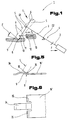
- the ski brake 1 shown schematically in FIG with 2 a brake lever and with 3 a crank arm of a brake arm 4 denotes, which is articulated on an axis of rotation D1 with a Footplate 5 is connected.
- the brake arm 4 is on one Ski-proof rotating or swiveling axis D2 swivel-mounted.
- the Step plate 5 is in its concrete construction with dash-dotted line, and it is as Locking lever with an operating section 6 (through an upwardly extended region of the tread plate 5 is formed is formed) and a locking section 7, which is shown in the Braking position of the ski brake 1 or the brake arm 4 in a ski-proof recess 8 engages.
- the locking recess 8 sets consists of a support surface 9 and a stop surface 10 together, the angle between the support surface 9 and the Stop surface 10, for example 90 ° to 105 °, more generally 90 ° up to 115 °.
- the support surface 9 can e.g. under a Angles from 30 ° to 60 °, in particular approx. 45 °, to the horizontal or top of the ski sloping backwards (to the right in Fig. 1) be provided.
- a cable pull 11 engages with the latching section 7 and is connected to a compression spring 12 which surrounds it over part of its length and is under tension, which is arranged in a ski-proof housing or a chamber 13 and is supported there, as a result of which a force F 2 is exerted on the locking section 7 of the tread plate 5.
- the angle between the brake arm 4 and the tread plate 5 in the braking position is at least essentially 90 °, which ensures that a force F acting on the braking arm 4 in the braking position does not cause the tread plate 5 to unintentionally disengage leads from the recess 8 as long as this braking force does not exceed a predetermined maximum value, for example 200 N.
- a force F 1 acting on the actuating lever arm 6, which is exerted on the tread plate 5 when stepping into the associated ski binding (not shown) with a ski boot - while depressing and pivoting the tread plate 5 - can cause a torque about the axis of rotation D1, whereby the tread plate 5 is pivoted or "disengaged" clockwise - as shown in Figure 1 - from the locking recess 8, in which case the brake arm 4 can be brought from the braking position into a standby position by pivoting about the ski-fixed axis of rotation D2. If the predetermined maximum force F is exceeded, with a suitable choice of the geometry and the materials (ie the angle ⁇ ) and the force F 2 of the spring 12, with which the spring is under tension, the latching section 7 can disengage from the latching recess 8.
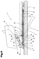
- the ski brake 1 is between a base plate 14, which are used to hold a heel holder of a ski binding (not shown), and a ski 15 has a spacer plate 16 arranged with a section 17 in the (ski) longitudinal direction protrudes forward over the base plate 14; In this section 17 of the spacer plate 16 is the locking recess 8 with the Support surface 9 and the stop surface 10 is formed.
- the tread plate 5 and one of two brake arms 4 are in Fig. 2 with full lines in the braking position, and with broken lines Lines shown in the ready position.
- the tread plate 5 is beveled towards the free end to a easier release of the tread plate 5 from the locking recess 8 through the heel part of a ski boot 18 when getting into the To enable ski binding (not shown).
- the cable 11 is attached; in detail is as shown in Fig.2 and in Fig.4 at the above the longitudinal axis of the ski shown upper half of the ski brake 1 (see also the 7) the one-piece cable pull 11 in a slot-shaped recess 19 at the lower end of the Tread plate 5 hooked under clamps and on both sides of the Step plate 5 each via a channel 20 in the holding plate 16 led backwards in the running direction and with the end at one Nipple 21 attached.
- a chamber 13 for receiving the respective compression spring 12 provided on the one hand on the nipple 21 and on the other at the shoulder-shaped transition 22 between the channel 20 and the Chamber 13 supports.
- the nipple 21 has an oblique bore 23, through which the cable 11 is guided, and a central threaded bore 24 with a screw 25, with the With the help of the cable 11 can be clamped in the respective position is, so that thereby the bias of the compression spring 12th is adjustable.
- each brake arm 4 is triple (approximately rectangular) cranked to a propeller shaft (pivot axis) 26 between the Brake lever 2 and the crank arm 3 and a pivot pin 27 on To form the free end of the crank arm 3, which in a bore 28th is rotatably mounted in the tread plate 5.
- the PTO shaft 26 lies directly on the base plate 14 and is on the side and supported upwards in a U-shaped recess 29 (see in particular Fig.
- Stand plate 31 arranged above the base plate 14 is rotatable stored.
- the two base strips 30 define the ski boot base area 30a and are connected to the base plate 14, e.g. by Rivets, screws (not shown) and / or via locking projections (see e.g. at 30 'in Fig. 3) etc., connected.
- the two Hinge pins 27 can also expand inward Bores 28 of the tread plate 5 engage, and on the two Stand strips 30 can be laterally perpendicular in the direction of the longitudinal axis of the ski projecting control projections 30b can be provided to the Brake arms 4 in the ready position with their two brake levers 2 retracted to a position above the top of the ski and largely within a normal projection control how this is conventional in itself, cf. also e.g. the EP-77 006 B1, where a similar movement sequence with the help of vertical trunnion is reached.
- each nipple is also 21 firmly connected by pinching to the cable pull 11 ', so that the bias of the compression spring 12 is rigid, i.e. is unchangeable.
- Figures 5 and 6 show a detail of a modified Ski brake, in which the locking recess 8 directly in the Base plate 14 'is formed, with a central, curved, optionally resilient tongue 34, the support surface 9 and two bent tabs 35 lying to the side of the tongue 34 Stop surface 10 (or two stop surfaces 10) for the Form footplate 5.
- Stop surface 10 or two stop surfaces 10 for the Form footplate 5.
- the arrangement could of these parts may also be reversed, i.e. a stop tab 35 is located in the middle between two outer support surface tongues 34.
- the ski brake can be used as above using the Figures 1 to 4 are designed so that there is a detailed description can be omitted.
- FIG. 7 shows in detail a spring 36 designed as a resilient tongue Support surface 9 'of a holding plate 16' made of resilient Plastic, in which a gap 37 in the part 17 'behind the tongue 36 the spacer plate 16 'is provided, which extends over the width the tread plate 5 extends.
- the underside of the tread plate 5 partly on the Top of the base plate 14 and partly at the highest point of the support surface 9, i.e. the highest point of the support surface 9 is aligned with the top of the base plate 14.
- the Locking section 7 of the tread plate 5 forms with the crank arm 3 of the Brake arm 4 a toggle joint, being kinematic Establish the axis of rotation D1 in the standby position above an imaginary connecting line between the axis of rotation D2 and the line of attack of the cable pull 11 lies on the tread plate 5.
- the tread plate 5 have a total length of 5 to 6 cm, the Length ratio of latching section 7 to actuating section 6 for example, generally 1.5: 1; the distance between the two Rotation axes D1 and D2 from each other are e.g. about 25 mm, and the Top of the tread plate 5 takes one in the braking position An angle of approx. 35 ° to the top of the ski.
Landscapes
- Braking Arrangements (AREA)
- Footwear And Its Accessory, Manufacturing Method And Apparatuses (AREA)
- Braking Elements And Transmission Devices (AREA)
- Mechanical Control Devices (AREA)
Description
Claims (12)
- Skibremse, bei welcher mindestens ein Bremsarm (4) um eine, im auf einem Ski montierten Zustand der Skibremse, allgemein parallel zur Skioberseite und im rechten Winkel zu der Längsachse des Ski (15) verlaufende skifeste Achse (D2) aus einer Bereitschaftsstellung in eine Bremsstellung und zurück schwenkbar gelagert ist, wobei der Bremsarm (4) mit einer Trittplatte (5) über eine parallel zur Schwenkachse (D2) des Bremsarmes (4) verlaufende Schwenkachse (D1) verbunden ist und die Trittplatte (5) durch mindestens eine Feder (12) in die Bremsstellung vorgespannt sowie gegen die Vorspannung der Feder (12) durch Niederdrücken in die Bereitschaftsstellung bringbar ist, in der das freie Ende des Bremsarmes (4) allgemein bis zur Höhe der Schwenkachse (D2) der Bremsarme (4) angehoben ist, und wobei sich in der Bremsstellung ein endseitiger Rastabschnitt (7) der Trittplatte (5) an einer im montierten Zustand der Skibremse im Bereich der Skioberseite vorgesehenen, skifesten Stützfläche (9; 9') abstützt und die Trittplatte (5) auf der dem Rastabschnitt gegenüberliegenden Seite über ihre Schwenkachse (D1) mit dem Bremsarm (4) hinaus verlängert ist, um einen Betätigungsabschnitt (6) zur Freigabe des Rastabschnittes (7) der Trittplatte (5) von der Stützfläche (9; 9') bei Niederdrücken der Trittplatte (5) zu bilden, dadurch gekennzeichnet, daß der Stützfläche (9; 9') eine zu ihr in einem Winkel zwischen 90° und 115° verlaufende Trittplatten-Anschlagsfläche (10) zugeordnet ist, die zusammen mit der Stützfläche (9; 9') eine Rastvertiefung (8) zum Einrasten des Rastabschnittes (7) der Trittplatte (5) bildet, wobei die Anordnung so getroffen ist, daß bei Angreifen einer vorbestimmten maximalen Kraft (F) am Bremsarm (4) ein Sicherheits-Ausrasten des Rastabschnittes (7) der Trittplatte (5) entgegen der Kraft (F2) der auf die Trittplatte (5) wirkenden Feder (12) erfolgt.
- Skibremse nach Anspruch 1, dadurch gekennzeichnet, daß der Winkel, unter dem die Anschlagsfläche (10) zur Stützfläche (9; 9') verläuft, zwischen 90° und 105° beträgt.
- Skibremse nach Anspruch 1 oder 2, dadurch gekennzeichnet, daß die Stützfläche (9; 9') als federnde Zunge (34; 36) ausgebildet ist.
- Skibremse nach einem der Ansprüche 1 bis 3, dadurch gekennzeichnet, daß am Rastabschnitt (7) der Trittplatte (5) eine Rolle (32) gelagert ist, welche in die Rastvertiefung (8) einrastet.
- Skibremse nach einem der Ansprüche 1 bis 4, dadurch gekennzeichnet, daß die Rastvertiefung (8) in einer zur Montage auf der Skioberseite vorgesehenen Grundplatte (14') ausgebildet ist.
- Skibremse nach einem der Ansprüche 1 bis 4, dadurch gekennzeichnet, daß unterhalb einer zur Montage auf der Skioberseite vorgesehenen Grundplatte (14; 14') eine mit einem Abschnitt (17) in Längsrichtung der Grundplatte (14; 14') über die Grundplatte (14; 14') vorstehende Distanzplatte (16; 16') angeordnet ist, wobei im vorstehenden Abschnitt (17) der Distanzplatte (16; 16') die Rastvertiefung (8) ausgebildet ist.
- Skibremse nach Anspruch 5 oder 6, dadurch gekennzeichnet, daß in der Grundplatte (14; 14') oder gegebenenfalls Distanzplatte (16; 16') zumindest ein im auf einem Ski montierten Zustand der Skibremse in Skilängsrichtung verlaufender Kanal (20) zur Führung eines Kabelzuges (11; 11') ausgebildet ist, der einerseits mit dem Rastabschnitt (7) der Trittplatte (5) und andererseits mit der Feder (12) verbunden ist.
- Skibremse nach Anspruch 7, dadurch gekennzeichnet, daß der Kabelzug (11; 11') mit einem Nippel oder dergl. (21) verbunden ist, der sich an einer den Kabelzug (11; 11') umschließenden Druckfeder (12) abstützt, welche in einer Kammer (13) beim Endabschnitt des Kanals (20) angeordnet und abgestützt ist.
- Skibremse nach Anspruch 8 mit Anspruch 4, dadurch gekennzeichnet, daß der Kabelzug (11') an der Achse (33) der Rolle (32) befestigt ist.
- Skibremse nach Anspruch 8 oder 9, dadurch gekennzeichnet, daß zur Veränderung der Vorspannung der Druckfeder (12) der Kabelzug (11; 11') verstellbar im Nippel (21) befestigt ist.
- Skibremse nach einem der Ansprüche 1 bis 10, dadurch gekennzeichnet, daß der den Betätigungsabschnitt (6) bildende Verlängerungsbereich der Trittplatte (5) zu seinem freien Ende hin abgeschrägt ist.
- Skibremse nach Anspruch 1, dadurch gekennzeichnet, daß der Winkel zwischen der Anschlagsfläche (10) und der Stützfläche (9; 9') kleiner als 90° + ρ ist, wobei tgρ der Reibungskoeffizient zwischen den Materialien der Trittplatte (5) und der Rastvertiefung (8) ist.
Applications Claiming Priority (3)
| Application Number | Priority Date | Filing Date | Title |
|---|---|---|---|
| AT0131595A AT408840B (de) | 1995-08-01 | 1995-08-01 | Skibremse |
| AT1315/95 | 1995-08-01 | ||
| PCT/AT1996/000114 WO1997004842A1 (de) | 1995-08-01 | 1996-06-28 | Skibremse |
Publications (2)
| Publication Number | Publication Date |
|---|---|
| EP0841970A1 EP0841970A1 (de) | 1998-05-20 |
| EP0841970B1 true EP0841970B1 (de) | 1999-03-10 |
Family
ID=3511242
Family Applications (1)
| Application Number | Title | Priority Date | Filing Date |
|---|---|---|---|
| EP96920622A Expired - Lifetime EP0841970B1 (de) | 1995-08-01 | 1996-06-28 | Skibremse |
Country Status (5)
| Country | Link |
|---|---|
| US (1) | US5839746A (de) |
| EP (1) | EP0841970B1 (de) |
| AT (2) | AT408840B (de) |
| DE (1) | DE59601430D1 (de) |
| WO (1) | WO1997004842A1 (de) |
Families Citing this family (3)
| Publication number | Priority date | Publication date | Assignee | Title |
|---|---|---|---|---|
| US6092828A (en) * | 1998-08-13 | 2000-07-25 | Schumacher; David | Snow ski traction device and method |
| DE19850297A1 (de) * | 1998-10-30 | 2000-05-04 | Marker Deutschland Gmbh | Skibremse mit Verrastung |
| GB0400323D0 (en) | 2004-01-08 | 2004-02-11 | New Transducers Ltd | Loudspeakers |
Family Cites Families (6)
| Publication number | Priority date | Publication date | Assignee | Title |
|---|---|---|---|---|
| FR2255926A1 (en) * | 1974-01-02 | 1975-07-25 | Salomon & Fils F | Lockable brake for a ski - has pedal controlled sprung anchor arm with automatic stops |
| DE2646091A1 (de) * | 1976-10-13 | 1978-04-27 | Maier | Skibremse |
| DE2906477C3 (de) * | 1979-02-20 | 1995-02-09 | Rohrmoser Alois Skifabrik | Skibremse |
| AT376891B (de) * | 1981-04-01 | 1985-01-10 | Tyrolia Freizeitgeraete | Skibremse |
| DE3140819A1 (de) * | 1981-10-13 | 1983-04-21 | ess GmbH Skibindungen, 8978 Burgberg | Skibremse |
| FR2610206B1 (fr) * | 1987-02-03 | 1989-02-10 | Salomon Sa | Frein de ski associe a une fixation de ski alpin, couramment appelee talonniere |
-
1995
- 1995-08-01 AT AT0131595A patent/AT408840B/de not_active IP Right Cessation
-
1996
- 1996-06-28 DE DE59601430T patent/DE59601430D1/de not_active Expired - Fee Related
- 1996-06-28 AT AT96920622T patent/ATE177330T1/de not_active IP Right Cessation
- 1996-06-28 EP EP96920622A patent/EP0841970B1/de not_active Expired - Lifetime
- 1996-06-28 WO PCT/AT1996/000114 patent/WO1997004842A1/de not_active Ceased
- 1996-06-28 US US08/836,905 patent/US5839746A/en not_active Expired - Fee Related
Also Published As
| Publication number | Publication date |
|---|---|
| DE59601430D1 (de) | 1999-04-15 |
| EP0841970A1 (de) | 1998-05-20 |
| WO1997004842A1 (de) | 1997-02-13 |
| ATA131595A (de) | 2001-08-15 |
| ATE177330T1 (de) | 1999-03-15 |
| US5839746A (en) | 1998-11-24 |
| AT408840B (de) | 2002-03-25 |
Similar Documents
| Publication | Publication Date | Title |
|---|---|---|
| DE1960002C3 (de) | Auslösende Skibindung mit einer verschwenkbaren Trittplatte | |
| AT515190B1 (de) | Ferseneinheit mit Bremsanordnung | |
| DE2612708A1 (de) | Skibremse | |
| DE3151162A1 (de) | Ausloeseskibindung | |
| AT395115B (de) | Bindung fuer langlaufski | |
| CH615351A5 (de) | ||
| DE3209519A1 (de) | Skibremse | |
| EP0264436B1 (de) | Sicherheitsskibindung, insbesondere fersenhalter | |
| AT406339B (de) | Snowboardbindung | |
| EP2091619A2 (de) | Vorrichtung zum anschluss eines schuhs an ein schneegleitgerät | |
| DE3202267A1 (de) | Fersenhalter einer skibindung mit skibremse | |
| AT408840B (de) | Skibremse | |
| DE2952860T1 (de) | ||
| EP0408855B1 (de) | Vorderbacken | |
| DE3421499A1 (de) | Sicherheitsskibindung | |
| DE1478141A1 (de) | Vorderbacken fuer Sicherheits-Skibindungen | |
| EP2826528A1 (de) | Vordereinheit einer Gleitbrettbindung | |
| DE1578726A1 (de) | Fersenausloesevorrichtung fuer Sicherheits-Skibindungen | |
| EP0774999B1 (de) | Vorderbacken für eine sicherheitsskibindung | |
| DE2429610B2 (de) | Sicherheitsskibindung | |
| DE2612770A1 (de) | Skibremse | |
| DE2702468C3 (de) | Auslöseskibindung | |
| DE3318143A1 (de) | Backen, insbesondere vorderbacken, einer skibindung | |
| DE2707769A1 (de) | Mit einer skibremse versehene skibindung | |
| DE3008806C2 (de) |
Legal Events
| Date | Code | Title | Description |
|---|---|---|---|
| PUAI | Public reference made under article 153(3) epc to a published international application that has entered the european phase |
Free format text: ORIGINAL CODE: 0009012 |
|
| 17P | Request for examination filed |
Effective date: 19971202 |
|
| AK | Designated contracting states |
Kind code of ref document: A1 Designated state(s): AT CH DE FR LI |
|
| GRAG | Despatch of communication of intention to grant |
Free format text: ORIGINAL CODE: EPIDOS AGRA |
|
| GRAG | Despatch of communication of intention to grant |
Free format text: ORIGINAL CODE: EPIDOS AGRA |
|
| GRAH | Despatch of communication of intention to grant a patent |
Free format text: ORIGINAL CODE: EPIDOS IGRA |
|
| 17Q | First examination report despatched |
Effective date: 19980630 |
|
| GRAH | Despatch of communication of intention to grant a patent |
Free format text: ORIGINAL CODE: EPIDOS IGRA |
|
| GRAA | (expected) grant |
Free format text: ORIGINAL CODE: 0009210 |
|
| AK | Designated contracting states |
Kind code of ref document: B1 Designated state(s): AT CH DE FR LI |
|
| REF | Corresponds to: |
Ref document number: 177330 Country of ref document: AT Date of ref document: 19990315 Kind code of ref document: T |
|
| REG | Reference to a national code |
Ref country code: CH Ref legal event code: EP |
|
| REF | Corresponds to: |
Ref document number: 59601430 Country of ref document: DE Date of ref document: 19990415 |
|
| ET | Fr: translation filed | ||
| PLBE | No opposition filed within time limit |
Free format text: ORIGINAL CODE: 0009261 |
|
| STAA | Information on the status of an ep patent application or granted ep patent |
Free format text: STATUS: NO OPPOSITION FILED WITHIN TIME LIMIT |
|
| 26N | No opposition filed | ||
| PG25 | Lapsed in a contracting state [announced via postgrant information from national office to epo] |
Ref country code: LI Free format text: LAPSE BECAUSE OF NON-PAYMENT OF DUE FEES Effective date: 20000630 Ref country code: CH Free format text: LAPSE BECAUSE OF NON-PAYMENT OF DUE FEES Effective date: 20000630 |
|
| REG | Reference to a national code |
Ref country code: CH Ref legal event code: PL |
|
| PGFP | Annual fee paid to national office [announced via postgrant information from national office to epo] |
Ref country code: AT Payment date: 20080616 Year of fee payment: 13 |
|
| PGFP | Annual fee paid to national office [announced via postgrant information from national office to epo] |
Ref country code: DE Payment date: 20080620 Year of fee payment: 13 |
|
| REG | Reference to a national code |
Ref country code: FR Ref legal event code: ST Effective date: 20100226 |
|
| PG25 | Lapsed in a contracting state [announced via postgrant information from national office to epo] |
Ref country code: FR Free format text: LAPSE BECAUSE OF NON-PAYMENT OF DUE FEES Effective date: 20090630 |
|
| PGFP | Annual fee paid to national office [announced via postgrant information from national office to epo] |
Ref country code: FR Payment date: 20080425 Year of fee payment: 13 |
|
| PG25 | Lapsed in a contracting state [announced via postgrant information from national office to epo] |
Ref country code: DE Free format text: LAPSE BECAUSE OF NON-PAYMENT OF DUE FEES Effective date: 20100101 Ref country code: AT Free format text: LAPSE BECAUSE OF NON-PAYMENT OF DUE FEES Effective date: 20090628 |