EP0839430B1 - Systeme de compression video - Google Patents
Systeme de compression video Download PDFInfo
- Publication number
- EP0839430B1 EP0839430B1 EP96923695A EP96923695A EP0839430B1 EP 0839430 B1 EP0839430 B1 EP 0839430B1 EP 96923695 A EP96923695 A EP 96923695A EP 96923695 A EP96923695 A EP 96923695A EP 0839430 B1 EP0839430 B1 EP 0839430B1
- Authority
- EP
- European Patent Office
- Prior art keywords
- video camera
- degree
- video
- compression
- adjustment
- Prior art date
- Legal status (The legal status is an assumption and is not a legal conclusion. Google has not performed a legal analysis and makes no representation as to the accuracy of the status listed.)
- Expired - Lifetime
Links
Images


Classifications
-
- H—ELECTRICITY
- H04—ELECTRIC COMMUNICATION TECHNIQUE
- H04N—PICTORIAL COMMUNICATION, e.g. TELEVISION
- H04N7/00—Television systems
- H04N7/18—Closed-circuit television [CCTV] systems, i.e. systems in which the video signal is not broadcast
-
- H—ELECTRICITY
- H04—ELECTRIC COMMUNICATION TECHNIQUE
- H04N—PICTORIAL COMMUNICATION, e.g. TELEVISION
- H04N7/00—Television systems
- H04N7/18—Closed-circuit television [CCTV] systems, i.e. systems in which the video signal is not broadcast
- H04N7/183—Closed-circuit television [CCTV] systems, i.e. systems in which the video signal is not broadcast for receiving images from a single remote source
-
- H—ELECTRICITY
- H04—ELECTRIC COMMUNICATION TECHNIQUE
- H04N—PICTORIAL COMMUNICATION, e.g. TELEVISION
- H04N19/00—Methods or arrangements for coding, decoding, compressing or decompressing digital video signals
- H04N19/10—Methods or arrangements for coding, decoding, compressing or decompressing digital video signals using adaptive coding
- H04N19/102—Methods or arrangements for coding, decoding, compressing or decompressing digital video signals using adaptive coding characterised by the element, parameter or selection affected or controlled by the adaptive coding
- H04N19/103—Selection of coding mode or of prediction mode
- H04N19/105—Selection of the reference unit for prediction within a chosen coding or prediction mode, e.g. adaptive choice of position and number of pixels used for prediction
-
- H—ELECTRICITY
- H04—ELECTRIC COMMUNICATION TECHNIQUE
- H04N—PICTORIAL COMMUNICATION, e.g. TELEVISION
- H04N19/00—Methods or arrangements for coding, decoding, compressing or decompressing digital video signals
- H04N19/10—Methods or arrangements for coding, decoding, compressing or decompressing digital video signals using adaptive coding
- H04N19/102—Methods or arrangements for coding, decoding, compressing or decompressing digital video signals using adaptive coding characterised by the element, parameter or selection affected or controlled by the adaptive coding
- H04N19/103—Selection of coding mode or of prediction mode
- H04N19/107—Selection of coding mode or of prediction mode between spatial and temporal predictive coding, e.g. picture refresh
-
- H—ELECTRICITY
- H04—ELECTRIC COMMUNICATION TECHNIQUE
- H04N—PICTORIAL COMMUNICATION, e.g. TELEVISION
- H04N19/00—Methods or arrangements for coding, decoding, compressing or decompressing digital video signals
- H04N19/10—Methods or arrangements for coding, decoding, compressing or decompressing digital video signals using adaptive coding
- H04N19/102—Methods or arrangements for coding, decoding, compressing or decompressing digital video signals using adaptive coding characterised by the element, parameter or selection affected or controlled by the adaptive coding
- H04N19/124—Quantisation
-
- H—ELECTRICITY
- H04—ELECTRIC COMMUNICATION TECHNIQUE
- H04N—PICTORIAL COMMUNICATION, e.g. TELEVISION
- H04N19/00—Methods or arrangements for coding, decoding, compressing or decompressing digital video signals
- H04N19/10—Methods or arrangements for coding, decoding, compressing or decompressing digital video signals using adaptive coding
- H04N19/134—Methods or arrangements for coding, decoding, compressing or decompressing digital video signals using adaptive coding characterised by the element, parameter or criterion affecting or controlling the adaptive coding
- H04N19/162—User input
-
- H—ELECTRICITY
- H04—ELECTRIC COMMUNICATION TECHNIQUE
- H04N—PICTORIAL COMMUNICATION, e.g. TELEVISION
- H04N19/00—Methods or arrangements for coding, decoding, compressing or decompressing digital video signals
- H04N19/10—Methods or arrangements for coding, decoding, compressing or decompressing digital video signals using adaptive coding
- H04N19/169—Methods or arrangements for coding, decoding, compressing or decompressing digital video signals using adaptive coding characterised by the coding unit, i.e. the structural portion or semantic portion of the video signal being the object or the subject of the adaptive coding
- H04N19/17—Methods or arrangements for coding, decoding, compressing or decompressing digital video signals using adaptive coding characterised by the coding unit, i.e. the structural portion or semantic portion of the video signal being the object or the subject of the adaptive coding the unit being an image region, e.g. an object
- H04N19/172—Methods or arrangements for coding, decoding, compressing or decompressing digital video signals using adaptive coding characterised by the coding unit, i.e. the structural portion or semantic portion of the video signal being the object or the subject of the adaptive coding the unit being an image region, e.g. an object the region being a picture, frame or field
-
- H—ELECTRICITY
- H04—ELECTRIC COMMUNICATION TECHNIQUE
- H04N—PICTORIAL COMMUNICATION, e.g. TELEVISION
- H04N19/00—Methods or arrangements for coding, decoding, compressing or decompressing digital video signals
- H04N19/10—Methods or arrangements for coding, decoding, compressing or decompressing digital video signals using adaptive coding
- H04N19/169—Methods or arrangements for coding, decoding, compressing or decompressing digital video signals using adaptive coding characterised by the coding unit, i.e. the structural portion or semantic portion of the video signal being the object or the subject of the adaptive coding
- H04N19/186—Methods or arrangements for coding, decoding, compressing or decompressing digital video signals using adaptive coding characterised by the coding unit, i.e. the structural portion or semantic portion of the video signal being the object or the subject of the adaptive coding the unit being a colour or a chrominance component
-
- H—ELECTRICITY
- H04—ELECTRIC COMMUNICATION TECHNIQUE
- H04N—PICTORIAL COMMUNICATION, e.g. TELEVISION
- H04N19/00—Methods or arrangements for coding, decoding, compressing or decompressing digital video signals
- H04N19/50—Methods or arrangements for coding, decoding, compressing or decompressing digital video signals using predictive coding
- H04N19/503—Methods or arrangements for coding, decoding, compressing or decompressing digital video signals using predictive coding involving temporal prediction
- H04N19/51—Motion estimation or motion compensation
- H04N19/513—Processing of motion vectors
- H04N19/521—Processing of motion vectors for estimating the reliability of the determined motion vectors or motion vector field, e.g. for smoothing the motion vector field or for correcting motion vectors
-
- H—ELECTRICITY
- H04—ELECTRIC COMMUNICATION TECHNIQUE
- H04N—PICTORIAL COMMUNICATION, e.g. TELEVISION
- H04N19/00—Methods or arrangements for coding, decoding, compressing or decompressing digital video signals
- H04N19/60—Methods or arrangements for coding, decoding, compressing or decompressing digital video signals using transform coding
- H04N19/61—Methods or arrangements for coding, decoding, compressing or decompressing digital video signals using transform coding in combination with predictive coding
-
- H—ELECTRICITY
- H04—ELECTRIC COMMUNICATION TECHNIQUE
- H04N—PICTORIAL COMMUNICATION, e.g. TELEVISION
- H04N19/00—Methods or arrangements for coding, decoding, compressing or decompressing digital video signals
- H04N19/80—Details of filtering operations specially adapted for video compression, e.g. for pixel interpolation
-
- H—ELECTRICITY
- H04—ELECTRIC COMMUNICATION TECHNIQUE
- H04N—PICTORIAL COMMUNICATION, e.g. TELEVISION
- H04N23/00—Cameras or camera modules comprising electronic image sensors; Control thereof
- H04N23/60—Control of cameras or camera modules
- H04N23/66—Remote control of cameras or camera parts, e.g. by remote control devices
- H04N23/661—Transmitting camera control signals through networks, e.g. control via the Internet
-
- H—ELECTRICITY
- H04—ELECTRIC COMMUNICATION TECHNIQUE
- H04N—PICTORIAL COMMUNICATION, e.g. TELEVISION
- H04N23/00—Cameras or camera modules comprising electronic image sensors; Control thereof
- H04N23/60—Control of cameras or camera modules
- H04N23/695—Control of camera direction for changing a field of view, e.g. pan, tilt or based on tracking of objects
Definitions
- the present invention relates generally to the field of video compression. More specifically, it relates to a system for using knowledge of the adjustment of a video camera to optimize the use of resources for compressing a video signal generated by the video camera.
- video surveillance cameras are commonly used to monitor premises for security purposes. Typically one or more video cameras are placed at various locations to be monitored. The output of the cameras may be viewed or recorded at a central station. It is also possible to have a number of video cameras distributed at locations which are remote from the central station. For example, cameras may be placed in several stores at various locations in a city and monitored from a central station. Remote cameras could also be placed at outlying parts of an airport and monitored centrally.
- Known video compression systems involve two basic forms of compression processing - spatial and temporal.
- Spatial processing compresses information by transforming the picture elements within a particular frame of a video signal in accordance with a compression algorithm, thereby reducing the amount of information required for reproduction of the frame.
- temporal processing takes into account the way in which information is changing with time. It therefore reduces the amount of information required for reproduction of a frame by taking into account changes in the picture which occur from frame to frame. These changes are reflected in motion vectors which are generated and transmitted instead of the actual contents of the video frames.
- a description of an implementation of spatial and temporal processing can be found in the MPEG compression recommendation ISO/IEC 1172-2 (referred to herein as the MPEG Standard).
- the MPEG Standard is one of several well known standards for video processing.
- Conventional MPEG encoders allow the degree of spatial processing to be varied, for example to conserve memory by adjusting the quantization of information in a particular frame.
- Such encoders also have the facility to detect motion of the picture from frame to frame and adjust the degree of temporal processing (i.e. adjust the motion vectors).
- motion can occur due to movement of the subject (e.g. a person traversing the field of view of the camera), or as a result of movement of the camera (i.e. due to the panning, tilting, zooming or focusing of the camera).
- movement information When the picture moves, the movement information must be extracted in order to generate motion vectors.
- Systems of the prior art e.g. systems using MPEG-type compression which perform temporal processing to convey motion information require relatively large amounts of memory space and computational power.
- US-A-5,144,450 discloses a video camera apparatus comprising a lens, and for generating video signals comprising a plurality of video images, compression means, camera control system for causing adjustment of the video camera.
- the camera control system comprises means for generating an adjustment indication signal indicative of adjustment of the video camera by the camera control system.
- a processor is included for outputting to the compression means, an instruction to vary the degree of compression processing in response to the adjustment indication signal.
- US-A-5,227,877 provides a high-efficient coding apparatus for video signal which is intended to control a quantizing step width finely depending on the quality of a inputted image.
- the coding apparatus is designed to obtain an average value of prediction errors at blocks, each block on which the orthogonal transform is carried out and to define the upper limit of a quantizing step width output from a quantizing step width control circuit depending on the average value. It results in making it possible to finely control the quantizing step width particularly based on each part of the image from a background to a dynamic area.
- US-A-4,511,886 discloses a security and surveillance system having a central monitoring station connected to a plurality of remote installations or subscribers by a transmission medium having a finite bandwidth.
- Each remote installation includes a plurality of surveillance equipment, including video, audio, and alarm signals, associated with a plurality of monitored locations.
- the security information collected by the surveillance equipment is serially sampled by a switcher which provides that information to an interface unit transmitter.
- the present invention is directed to the use of known information about the movement of the video picture caused by movement due to the camera to reduce the computational and memory overhead required for compression of video data. Specifically, it uses information generated as a result of adjustments to the camera to adjust and thus trade off spatial processing against temporal processing. Rather than extracting the information from the video pictures, it obtains the information from the means by which the camera is actually being controlled.
- the present invention is a video camera apparatus with compression processing and a method used with such an apparatus as claimed in claims 1 and 26.
- the apparatus includes an adjustable video camera.
- the camera generates video signals made up of a plurality of video images.
- a camera control system causes pan, tilt, zoom or focus adjustment of the video camera.
- the camera control system comprises means for generating an adjustment indication signal indicative of adjustment of the video camera by the camera control system.
- Compression means effector degree of compression processing on the video signals, whereby the compression means comprise means for effecting a degree of spatial compression processing on the video signals and means for effecting a degree of temporal compression processing on the video signals including means for generating motion vectors in response to the adjustment indication signal.
- a processor outputs to the compression means, an instruction to vary the degree of compression processing in response to the adjustment indication signal produced by the control system.
- the instruction varies the degree of compression processing comprising instructions to vary the degree of spatial compression processing and the degree of temporal compression processing in response to the adjustment indication signal. This a priori knowledge of the adjustment of the camera derived from the control system is thus used to vary the degree of compression processing.
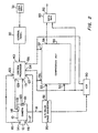
- Video camera apparatus 1 shown in Fig. 1 is made up of pan-tilt-zoom video camera 10 having A/D color space converter 20 and pan-tilt-zoom ("PTZ") unit 18, control panel 30 with user input 32, control interpreter 40 (a suitably programmed microprocessor with associated memory) and a compression unit 50.
- Camera 10 produces a video signal 19 (made up of video images comprising picture elements) which is fed into color space converter 20, which in turn outputs digital chrominance and luminance signals Cr, Cb and Y at output 52.
- Camera 10 has zoom lens 12 having focus control mechanism 14 and zoom control mechanism 16.
- PTZ mechanism 18 enables camera 10 to pan, tilt and zoom on instructions input at control panel 30.
- Control panel 30 and control interpreter 40 are preferably included in a single microprocessor based unit available from Sensormatic Electronics Corp. of Deerfield Beach, Florida under the name “Touchtracker.”
- Camera 10, with its associated lens and PTZ unit 18 and color space converter 20 are preferably included in a self-contained "dome” available form Sensormatic Electronics corp. under the name “SpeedDome.”
- Compression unit 50 is a conventional video compression unit comprising hardware and software which implements a compression algorithm - preferably the well-known MPEG system as described in the MPEG Standard.
- the MPEG Standard describes a system which effects a degree of compression processing (including spatial and temporal compression). Any compression system where the degree of compression processing can be varied can be used.
- known systems having compression filters (having predetermined filter length, shape and coefficients) in which the degree of spatial compression is varied by adjusting filter length, adjusting filter coefficients or adjusting filter shape can be used and are considered to be equivalents represented by compression unit 50. Since the video compression hardware and software are well known to persons of ordinary skill in the art, only the aspects which are germane to this invention will be described.
- Compression unit 50 has an input 53 connected to output 52 of color space converter 20 for receiving digitized chrominance signals Cr and Cb and luminance signal Y. It also has an input 55 for receiving motion vectors produced by control interpreter 40 at output 54. The generation and purpose of these motion vectors will be described below.
- Input 57 of compression unit 50 receives instructions as to the degree of spatial processing from output 56 of control interpreter 40, the details of which will be described below.
- Compression unit 50 has an output 58 for outputting a compressed video signal to multiplexer 80 for transmission over a communication channel.
- the basic components of the preferred compression unit 50 are as follows: subtractor 60, discrete cosine transform unit 62, quantizer 64, variable length coder 66, de-quantizer 68, inverse discrete cosine transform unit 70, summing point 72 and picture store predictor 74.
- Quantizer 64 quantizes the discrete cosine transformed signal supplied by discrete cosine transform unit 62.
- the degree to which quantizer 64 effects spatial compression processing of the supplied signal is variable.
- quantizer 64 has at least two quantization matrices, each of which causes a different degree of spatial compression processing. Writing a variable into register 65 via input 57 causes one of the quantization matrices to be selected. All of these components are well known to persons of ordinary skill in the art, being described in detail in the MPEG manual.
- the MPEG standard includes two modes of compression processing - spatial and temporal.
- compression unit 50 compresses information within a video frame generated by video camera 10.
- Each video frame carries images made up of a large number of picture elements.
- motion vectors are generated to describe changes in a picture from one frame to another. The motion vectors thus are an indication of the motion of the images carried by the video frames.
- the compression operation When the camera is in motion, zooming or focusing, in order for the signal to be accurately reconstructed, the compression operation must convey more information as to how the picture is changing. This requires greater bandwidth than when the camera is stationary. Increasing the degree of spatial compression (i.e. increasing the spatial quantization) frees bandwidth for temporal compression processing (i.e. the generation of motion vectors) in response to panning, tilting, zooming or focusing. However, this results in less detail appearing when the compressed signal is reconstructed. Nevertheless, this is an acceptable solution because the human eye is less sensitive to detail in a moving object than in a still one.
- control interpreter 40 When camera 10 is stationary, focused and lens 12 is not being zoomed, control interpreter 40 does not perform temporal compression processing (i.e., it does not produce motion vectors).
- the degree of spatial compression is low. That is to say, a quantization matrix giving a low quantization is selected by writing an appropriate value into register 65. This results in a high degree of detail being conveyed in the compressed signal at output 58.
- the video signals at output 52 which are fed into compression unit 50 at input 53 are compressed in accordance with the MPEG algorithm using the degree of spatial compression processing set by control interpreter 40 and made available as a compressed video signal at output 58.
- This signal is passed to output 82 by multiplexer 80 for transmission over a communications channel or to a storage device.
- Control panel 30, control interpreter 40 and PTZ unit 18 make up a camera control system.
- control panel 30 When the user instructs camera 10 to pan, tilt, zoom or focus by means of user input 32, control panel 30 produces a control signal at output 31. This is fed into control interpreter 40 at input 41.
- control interpreter 40 generates an adjustment indication signal at output 42 which is provided to input 43 of PTZ unit 18 to cause camera 10 to pan, tilt, zoom, or focus.
- control interpreter 40 In response to the adjustment indication signal, control interpreter 40 generates a series of motion vectors.
- the motion vectors describe how the picture produced by camera 10 is changing due to the instruction received from the user.
- the motion vectors are output in a format dictated by the MPEG standard, thus effecting temporal compression processing.
- the motion vectors are stored in a lookup table in the memory of control interpreter 40.
- a lookup table in the memory of control interpreter 40.
- Vectors indicative of combined panning, tilting, zooming or focusing are obtained by multiplying each of the vectors associated with the particular degree of panning, tilting, zooming or focusing by each other.
- the motion vectors are fed into multiplexer 80 and multiplexed with the compressed signal produced as a result of the spatial compression.
- control interpreter 40 When the camera control system causes camera 10 to be adjusted (panned, tilted, zoomed or focused), control interpreter 40 outputs an instruction to compression unit to increase the degree of spatial compression processing.
- control interpreter instructs quantizer 64 to select the quantization matrix to produce a higher degree of spacial compression to adjust its guantization to a higher level by causing the appropriate value to be written into register 65.
- control interpreter 40 outputs instructions to compression unit 40 to increase or decrease the degree of spatial compression processing in appropriate proportion.
- the compression operation is weighted towards the frame to frame changes in the picture (temporal compression processing), rather than towards the details of each frame (spacial compression processing).
- control interpreter 40 stops producing the motion vectors. It also causes the degree of spatial compression processing to be adjusted back to an appropriate lower level.
- the system just described allows the degree of compression processing to be varied depending on adjustment of the video camera. This allows a tradeoff between the degree spatial and temporal processing on the basis of a priori knowledge of whether the camera is panning, tilting, zooming or focusing.
- the system has been described by reference to a system in which the degree of spatial compression processing is varied by adjusting the quantization of an MPEG-type compression processing system.
- a person of ordinary skill in the art will recognize that the principles of the preferred embodiment of this invention are equally applicable to systems which use the different forms of compression processing and in which the degree of compression processing can be varied.
- the system can also have the capability to record the video images produced by camera 10.
- the instructions to vary the degree of compression processing are provided to video cassette recorder 90 and stored on the video tape between frames of the video signal. That is to say, the instructions output by control interpreter 50 and/or the motion vectors are stored on the video tape.
- the instructions to vary the degree of spatial and/or temporal compression and the motion vectors are extracted from the recorded signal and used in the manner described above.
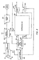
- the adjustment indication signals are produced by transducers which detect the state of panning, tilting, zooming or focusing, rather than control signals produced by the control panel.
- Transducer 118 detects the state of panning of camera 10 and produces a panning adjustment signal at output 119.
- Transducer 120 detects the state of tilting of camera 10 and produces a tilting adjustment signal at output 121.
- Transducer 114 detects the state of zooming of lens 12 and produces a zoom indicating signal at output 115.
- Transducer 116 detects the state of focusing of lens 12 and produces a focus adjustment signal at output 117.
- transducers 114, 116, 118 and 120 are fed into processor inputs 125, 127, 129 and 132 respectively.
- Processor 140 produces outputs 154 and 156. Those outputs are identical to outputs 54 and 56 described above and are used in the same way.
- FIG. 3 A third embodiment of the invention is shown in Fig. 3.
- This third embodiment is identical to the first embodiment, except that it includes simplified fine motion estimator 90.
- This unit is identical to a conventional motion estimator described in the MPEG Standard.
- Motion estimator 90 receives at input 91 the signal produced by color space converter 20. It produces at outputs 92 and 93 composite motion vectors in accordance with the MPEG Standard. Those vectors are multiplied by the vectors produced by control interpreter 40 to produce a more refined motion vector.
- the systems described above are designed to be part of a video surveillance system which allows monitoring from a remote location.
- the following is a description of such a system.
- a video surveillance system 210 incorporating the above-described apparatus is shown in block diagram form in Fig. 4.
- the surveillance system described below incorporates the first embodiment of the invention (Fig. 1). However, the following description will enable a person of ordinary skill in the art to make a surveillance system incorporating the first, second or third embodiment.
- System 210 is made up of monitoring station 220 and video camera module 240.
- Monitoring station 220 communicates with video camera module 240 via public switched communications network 280.
- Network 280 is preferably a standard telephone network such as that operated by a local telephone company.
- Network 280 may for example also be a fiber optic network, a cellular network, a local area network such as an ethernet or a local ISDN network.
- system 210 is described and illustrated with only one monitoring station and one camera module, a plurality of monitoring and camera modules can be connected via the communications network utilizing the switching capabilities of the network.
- Video camera module 240 having video camera 242 is at a location which is remote from monitoring station 220.
- the camera module may be in one of several stores at various locations in a town.
- the present invention allows all camera modules to be monitored from a central monitoring location via a public telephone network.
- a large airport may be another site for system 210.
- Outlying buildings may be monitored from a central location. The outlying locations are likely to be connected to the central monitoring location via the telephone network so, using the present invention, no additional wiring is needed to connect the video camera module to the monitoring station.
- Monitoring station 220 has a network interface 222 for connection of the monitoring station to network 280.
- Network interface 222 is made up of a telephone line interface 223 and communications hardware 224 - contained in an ISDN basic rate interface or a modem.
- Networks of the type with which the present invention is intended to function typically operate at speeds of between 28 and 128 thousand bits per second. However, video data typically requires transmission speeds of approximately 80 million bits per second.
- the video data acquired by camera 242 is therefore compressed at camera module 240 by means of the compression system described above.
- Signal processor 226 is thus provided for decompressing compressed image signals received from camera module 240.
- Network interface 222 and decompression circuit 226 are controlled by microprocessor 228 - for example a Motorola 68030, Intel 486 or equivalent microprocessor.
- Monitoring station 220 includes a video monitor 230. Microprocessor 228 controls the overall operation of monitoring station 220. To allow the flow of control signals, data bus 236 connects microprocessor 228 to network interface 222.
- a user interface in the form of keyboard 232 and mouse or trackball input device 234 (preferably a Touchtracker camera controller available from Sensormatic Electronics Corp. of Deerfield Beach, Florida) is provided to enable the operator to enter instructions which microprocessor 228 causes to be transmitted to video camera module 240 via communications network 280. Instructions can thus be transmitted from monitoring station 220 to camera module 240 in order to control remotely any of the operations of camera module 240. For example, the user can instruct camera 242 to pan, tilt, zoom or focus.
- Keyboard 232 and input device 234 thus perform the functions of control panel 30 and user input 32 described above with reference to Fig. 1. Systems for performing such control operations are disclosed in copending U.S. Patent Application No. 08/166,599.
- the control signals are transmitted to camera module 240 over communications, channel 280.
- Camera module 240 is an integrated unit including a video surveillance camera 242 for monitoring an area, video compression unit 246 and network interface 250. Camera 242 generates video image signals 244 which are fed into video compression unit 246.
- Compression unit 246 is the same as video compression unit 50 described above with reference to Fig. 1.
- Video compression unit 246 is preferably a video compression set available from Integrated Information Technology, Inc. of Santa Clara, California under the name Vision Controller/Vision Processor or equivalent compression circuitry. It includes data multiplexer 80 described above.
- the processed signals 248 are fed into network interface 250 which connects camera 242 to network 280.
- Network interface 250 made up of communications hardware 252 and line interface 254, is essentially the same as network interface 222 in monitoring station 220.
- Microprocessor 256 which may be of the of the same type as microprocessor 228, controls the operation of camera 242, and network interface 250.
- Data bus 258 carries control data between microprocessor 256 and camera 242, video compression hardware 246 and network interface 250.
- Microprocessor 228 receives (via communications channel 280) the control signals generated by keyboard 232, input device 234 and microprocessor 228.
- Microprocessor 256 is also programmed to perform the functions of control interpreter 40 described above with reference to Fig. 1. That is to say, microprocessor 228 converts the control signals it receives into camera adjustment indication signals which are transmitted to camera 242 over data bus 258.
- Instructions to compression unit 246 to alter the compression parameter are also produced by microprocessor 256 in response to the camera adjustment indication signals and provided to the appropriate pin of compression unit 246 via data bus 258. Motion vectors are likewise generated in response to the camera adjustment indication signals by microprocessor 256 and supplied to compression unit 246 to be multiplexed.
- Camera module 240 is provided with memory capability in the form of a digital first-in-first-out (FIFO) memory 266 comprising a disk drive or random access memory.
- Memory 266 stores the processed image signals 248 over a predetermined time period, for example 3 minutes. Memory 266 therefore keeps a continuous record of what camera 242 has acquired over the preceding predetermined time period.
- Memory 266 is connected to microprocessor 256 by data bus 258.
- Further storage unit 270 in the form of a video cassette recorder (VCR) disk or random access memory is connected to camera 242 and compression unit 246 such that it can record the output of camera 242 and play back into compression unit 246.
- outputs 54 and 56 of control interpreter 40 are stored along with the output of camera 242.
- Storage unit 270 can be used in a variety of ways, some of which are described below.
- the operation of storage unit 270 can be controlled by microprocessor 256 via data bus 258. Any electronically controllable VCR can be used, for example, the Panasonic AG-6730.
- Camera module 240 also includes a motion detector 260 which analyzes video image signals 244 output by camera 242 to determine whether the subject of the surveillance by camera 242 has moved.
- Motion detector is connected to microprocessor 256 by means of data bus 258.
- Camera module 240 is also provided with an alarm device interface 268 connected to microprocessor 256.
- Alarm device interface facilitates the receipt by microprocessor 256 of various different types of alarms thereby triggering recording in memory 266 or on storage unit 270 or transmission over network 280. If motion detector 260 detects movement in the subject or if an alarm signal is received via alarm interface 268, a signal 262 is generated and sent to microprocessor 256.
- Microprocessor 256 generates a start signal 264 in response to signal 262, thereby causing second interface 250 to begin transmitting video images processed by signal processor 246 over network 280.
- microprocessor 256 can initiate various operations. For example, it can instruct storage unit 270 to start recording, change the mode of recording from time lapse to real time, cause the output of camera 242 to be compressed and transmitted over network 280 or cause the contents of memory 266 or storage unit 270 to be output to network 280, all depending on the manner in which microprocessor 256 is programmed and how the system is configured. Start signal 264 can also be initiated from monitoring station 220.
- Line interfaces 223 and 254 are able to initiate communications by dialing each other or dialing other modules connected to network 280.
- microprocessor 256 generates a start signal as described above (e.g. in response to the detection of motion)
- line interface 254 of camera module 240 dials up monitoring station 220.
- the call is received by line interface 223 of monitoring station 220.
- a handshaking process between camera module 240 and monitoring station 220 is then initiated, resulting in the reception by interface 222 of compressed video data from interface 250.
- Decompression circuit 226 decompresses the received compressed data so that it can be displayed on monitor 230.
- microprocessor 228 can initiate communications by causing monitoring station 220 to dial camera module 240 and receive data from camera 242, storage unit 270 or memory 266.
- the operation of each element of camera module 240 can be controlled from monitoring station 220 once communication has been established between the camera module and the monitoring station.
- the invention can preferably operate in two modes.
- monitoring station 220 dials up camera module 240 by initiating a call using first network interface 222.
- a user at monitoring station 220 can control the operation of camera module 240 remotely by means of keyboard 232 or input device 234.
- the user could instruct camera module 240 to output the contents of memory 266, play back the contents of storage unit 270 or simply monitor the output of camera 242 in real time.
- camera module 240 initiates a call to monitoring station 220.
- an alarm event detected by camera module 240 may cause it to initiate a call to monitoring station 220.
- Camera module 240 will then transmit live data acquired by camera 242, play back the contents of 266 or storage unit 270.
- Fig. 5 is a flow chart of a preferred method of operation. The steps of the method described in Fig. 5 are indicated by numerals preceded by an "S.”
- the operation of camera module 240 commences with the powering up of camera module 240 and the initialization of video compression hardware 246 (steps S1 and S2).
- the initialization of compression unit 246 includes the downloading of operation codes to the RISC processor of compression unit 256 as well as the downloading of parameters such as the data rate and initial quantization parameter for the compression process.
- Microprocessor 256 continuously monitors alarm interface 268 and motion detector 260 (S3).
- microprocessor 256 sends an instruction along data bus 258 to storage unit 270 to start recording and a timer is set within the microprocessor (S4). Recording continues for a predetermined time T1 (S5). At the end of T1, microprocessor 256 instructs communications hardware 252 to initiate a call to monitoring station 220 over network 280 (S6). A predetermined number of attempts are made to complete the call until the call is successful (S7). If the call is successful, microprocessor 256 instructs storage unit 270 to output what it has just recorded into compression unit 246. Alternatively, this step can be bypassed if the information is stored in storage unit 270 in compressed form.
- Microprocessor 256 instructs communications hardware 252 to transmit the compressed output of compression unit 246 through network 280 (S9) to monitoring station 220.
- the compressed data is decompressed by decompression unit 226 and the images recorded by storage unit 270 are displayed on monitor 230.
- memory 266 could be substituted for storage unit 270.
- microprocessor 256 could transmit the real time output of camera 242 in compressed form along network 280.
- the video data output of camera 242 can be continuously stored in memory 266 over a period of time equal to T.
- the compressed video data stored over the immediately preceding T seconds is output by memory 266, and transmitted to monitoring station 220. This allows the monitoring module to obtain information about what happened immediately before the triggering event.
- a second standby storage unit in addition to storage unit 270 can be added so that at any given time the output of video camera 242 would be recorded. That is to say that when one storage unit fills up, the other begins to record and the first stands by for the second to fill up.
- video data sampled at predetermined intervals could be stored in memory 266.
Landscapes
- Engineering & Computer Science (AREA)
- Multimedia (AREA)
- Signal Processing (AREA)
- Studio Devices (AREA)
- Closed-Circuit Television Systems (AREA)
- Compression Or Coding Systems Of Tv Signals (AREA)
Claims (27)
- Dispositif de caméra vidéo (1) comprenant une caméra vidéo comprenant un objectif, et destiné à générer les signaux vidéo comprenant une pluralité d'images vidéo,
un système de commande de caméra destiné à provoquer le réglage en panoramique, inclinaison, changement de focale ou mise au point de la caméra vidéo (10), le système de commande de caméra comprenant un moyen destiné à générer un signal d'indication de réglage indicatif dudit réglage en panoramique, inclinaison, changement de focale ou mise au point de la caméra vidéo (10) par le système de commande de caméra,
un moyen de compression appliquant un degré de traitement de compression sur les signaux vidéo, ledit moyen de compression comprenant : un moyen destiné à appliquer un degré de traitement de compression dans l'espace ou spatial sur les signaux vidéo,
ledit moyen de compression comprenant en outre un moyen destiné à appliquer un degré de traitement de compression dans le temps sur les signaux vidéo comprenant un moyen destiné à générer des vecteurs de mouvement en réponse au signal d'indication de réglage, et
un processeur (40, 140) destiné à fournir en sortie au moyen de compression, une instruction pour faire varier le degré de traitement de compression en réponse au signal d'indication de réglage, ladite instruction destinée à faire varier le degré de traitement de compression comprenant des instructions pour faire varier le degré de traitement de compression dans l'espace et le degré de traitement de compression dans le temps en réponse au signal d'indication de réglage. - Dispositif de caméra vidéo selon la revendication 1,
caractérisé en ce que
le moyen destiné à appliquer un degré de compression dans l'espace comprend un quantificateur (64) destiné à appliquer un degré de quantification des signaux vidéo, et où l'instruction pour faire varier le degré de traitement de compression dans l'espace en réponse au signal d'indication de réglage comprend une instruction vers le moyen de compression pour faire varier le degré de quantification des signaux vidéo par le quantificateur (64). - Dispositif de caméra vidéo selon la revendication 1,
caractérisé en ce que
le moyen destiné à appliquer un degré de compression dans l'espace comprend au moins un filtre de compression présentant une longueur de filtre, et où l'instruction pour faire varier le degré de compression dans l'espace en réponse au signal d'indication de réglage comprend une instruction pour faire varier la longueur du filtre. - Dispositif de caméra vidéo selon la revendication 1,
caractérisé en ce que
le moyen destiné à appliquer un degré de compression dans l'espace comprend un filtre présentant une pluralité de coefficients de filtre, et où l'instruction pour faire varier le degré de compression dans l'espace en réponse au signal d'indication de réglage comprend une instruction pour faire varier au moins l'un des coefficients du filtre. - Dispositif de caméra vidéo selon la revendication 1,
caractérisé en ce que
le moyen destiné à appliquer un degré de compression dans l'espace comprend un filtre de compression présentant une forme de filtre, et où l'instruction pour faire varier le degré de compression dans l'espace en réponse au signal d'indiction de réglage comprend une instruction pour faire varier la forme du filtre. - Dispositif de caméra vidéo selon la revendication 1,
caractérisé en ce que
le système de commande de caméra comprend une commande à distance. - Caméra vidéo selon la revendication 6,
caractérisée en ce que
la commande à distance comprend un moyen destiné à générer un signal de commande pour provoquer un réglage de la caméra vidéo (1), où le signal de commande est fourni au moyen destiné à générer un signal d'indication de réglage et où le moyen destiné à générer un signal d'indication de réglage génère le signal d'indication de réglage en réponse au signal de commande. - Dispositif de caméra vidéo selon la revendication 1,
caractérisé en ce que
le système de commande de caméra comprend un transducteur destiné à détecter le réglage de la caméra vidéo (10) et à générer le signal d'indication de réglage en réponse à la détection du réglage de la caméra vidéo (10). - Dispositif de caméra vidéo selon la revendication 1,
caractérisé en ce que
le processeur fournit en sortie une instruction au moyen de compression d'augmenter le degré de traitement de compression dans l'espace au début du réglage de la caméra vidéo. - Dispositif de caméra vidéo selon la revendication 1,
caractérisé en ce que
le processeur (40, 140) fournit en sortie une instruction au moyen de compression pour diminuer le degré de traitement de compression dans l'espace à l'arrêt du réglage de la caméra vidéo (10). - Dispositif de caméra vidéo selon la revendication 1,
caractérisé en ce que
le processeur fournit en sortie une instruction au moyen de compression pour faire varier le degré de traitement de compression dans l'espace en proportion du réglage de la caméra vidéo (10). - Dispositif de caméra vidéo selon la revendication 1,
caractérisé en ce que
lesdits vecteurs de mouvement comprennent des informations se rapportant à des modifications d'une trame à l'autre des images vidéo. - Dispositif de caméra vidéo selon la revendication 1,
caractérisé en ce que
elle comprend en outre un moyen destiné à analyser les images vidéo afin de déterminer si les images vidéo sont animées, et destiné à générer des vecteurs de mouvement si les images vidéo de l'image sont animées, les vecteurs de mouvement comprenant des informations se rapportant au mouvement des images vidéo. - Dispositif de caméra vidéo selon la revendication 1,
caractérisé en ce que
le signal d'indication de réglage indique un mouvement panoramique de la caméra vidéo (10). - Dispositif de caméra vidéo selon la revendication 1,
caractérisé en ce que
le signal d'indication de réglage indique une inclinaison de la caméra vidéo (10). - Dispositif de caméra vidéo selon la revendication 1,
caractérisé en ce que
le signal d'indication de réglage indique un changement de focale de l'objectif. - Dispositif de caméra vidéo selon la revendication 1,
caractérisé en ce que
le signal d'indication de réglage indique une mise au point de l'objectif. - Dispositif de caméra vidéo selon la revendication 1,
caractérisé en ce que
elle comprend en outre un moyen destiné à mémoriser les signaux vidéo sur un support de mémorisation, et où l'instruction pour faire varier le degré de traitement de compression est mémorisée sur le support de mémorisation. - Dispositif de caméra vidéo selon la revendication 18,
caractérisé en ce que
elle comprend en outre un moyen destiné à mémoriser les signaux vidéo sur un support de mémorisation, et où l'instruction pour faire varier le degré de traitement de compression dans le temps est mémorisée sur le support de mémorisation. - Dispositif de caméra vidéo selon la revendication 1,
caractérisé en ce que
si le réglage de la caméra vidéo est tel que les images vidéo bougent, le degré de traitement de compression dans l'espace est diminué, et le degré de compression dans le temps est augmenté. - Dispositif de caméra vidéo selon l'une quelconque des revendications précédentes,
caractérisé en ce que
le dispositif de caméra vidéo fait partie d'un système de surveillance vidéo destiné à la surveillance d'un emplacement à distance, le système comprenant :un module de caméra vidéo (240) à l'emplacement à distance, le module de caméra vidéo (240) comprenant :une caméra vidéo (242) destinée à générer des signaux vidéo,une première interface de réseau (250) reliant le module de caméra vidéo (240) à un réseau de communications, de sorte que le module de caméra vidéo étant relié au réseau de communications, le module de caméra vidéo (240) peut communiquer avec un poste de surveillance (220) sur le réseau de communications. - Dispositif de caméra vidéo selon la revendication 21 comprenant en outre un poste de surveillance (220) comprenant une seconde interface de réseau (222) en vue d'une connexion au réseau.
- Dispositif de caméra vidéo selon la revendication 19 comprenant en outre un moyen destiné à mémoriser les signaux vidéo sur un support de mémorisation, et où l'instruction pour faire varier le degré de traitement de compression dans le temps est mémorisée sur le support de mémorisation.
- Dispositif de caméra vidéo selon la revendication 1,
caractérisé en ce que
la caméra vidéo (10) comprend un objectif et est destinée à générer des signaux vidéo comprenant une pluralité d'images vidéo comprenant des éléments d'images. - Dispositif de caméra vidéo selon la revendication 1,
caractérisé en ce que
le système de commande de caméra comprend un moyen destiné à recevoir ledit signal de commande et à générer un signal d'indication de réglage indicatif du réglage de la caméra vidéo par le système de commande de caméra en réponse au signal de commande reçu. - Procédé destiné à une utilisation dans un système de caméra vidéo comprenant une caméra vidéo réglable (10, 242) et un contrôleur destiné à régler en panoramique, en inclinaison, en changement de focale ou en mise au point la caméra vidéo (10, 242), comprenant les étapes consistant à :générer les signaux vidéo comprenant une pluralité d'images vidéo,régler la caméra vidéo (10, 242) et générer un signal d'indication de réglage indicatif dudit réglage en panoramique, en inclinaison, en changement de focale ou en mise au point de la caméra vidéo (10, 242),appliquer un degré de traitement de compression sur les signaux vidéo, en générant ainsi des signaux vidéo compressés, ladite application du degré de traitement de compression comprenant : appliquer le degré de traitement de compression dans l'espace sur les signaux vidéo, et appliquer le degré de traitement de compression dans le temps sur les signaux vidéo comprenant la génération de vecteurs de mouvement en réponse au signal d'indication de réglage,fournir en sortie au moyen de compression, une instruction pour faire varier le degré de traitement de compression en réponse au signal d'indication de réglage, ladite instruction pour faire varier le degré de traitement de compression comprenant des instructions pour faire varier le degré de traitement de compression dans l'espace et le degré de traitement de compression dans le temps en réponse au signal d'indication de réglage.
- Procédé selon la revendication 26,
caractérisé en ce que
l'étape consistant à appliquer un degré de traitement de compression comprend l'étape consistant à appliquer un degré de compression dans le temps des signaux vidéo et dans lequel un processeur fournit en sortie en outre une instruction au moyen de compression pour faire varier le degré de compression dans le temps en réponse au signal d'indication de réglage.
Applications Claiming Priority (3)
| Application Number | Priority Date | Filing Date | Title |
|---|---|---|---|
| US08/502,576 US5926209A (en) | 1995-07-14 | 1995-04-14 | Video camera apparatus with compression system responsive to video camera adjustment |
| US502576 | 1995-07-14 | ||
| PCT/US1996/011418 WO1997004597A1 (fr) | 1995-07-14 | 1996-07-08 | Systeme de compression video |
Publications (3)
| Publication Number | Publication Date |
|---|---|
| EP0839430A1 EP0839430A1 (fr) | 1998-05-06 |
| EP0839430A4 EP0839430A4 (fr) | 1998-09-30 |
| EP0839430B1 true EP0839430B1 (fr) | 2003-09-24 |
Family
ID=23998431
Family Applications (1)
| Application Number | Title | Priority Date | Filing Date |
|---|---|---|---|
| EP96923695A Expired - Lifetime EP0839430B1 (fr) | 1995-07-14 | 1996-07-08 | Systeme de compression video |
Country Status (10)
| Country | Link |
|---|---|
| US (1) | US5926209A (fr) |
| EP (1) | EP0839430B1 (fr) |
| JP (1) | JP4235259B2 (fr) |
| KR (1) | KR19990028825A (fr) |
| AR (1) | AR002822A1 (fr) |
| AU (1) | AU716417B2 (fr) |
| BR (1) | BR9609700A (fr) |
| CA (1) | CA2226324C (fr) |
| DE (1) | DE69630121T2 (fr) |
| WO (1) | WO1997004597A1 (fr) |
Families Citing this family (207)
| Publication number | Priority date | Publication date | Assignee | Title |
|---|---|---|---|---|
| US6314140B1 (en) * | 1995-12-28 | 2001-11-06 | Lucent Technologies Inc. | Dynamic video focus control |
| JPH09289631A (ja) * | 1996-02-20 | 1997-11-04 | Canon Inc | 撮像制御方法及び装置及び撮像システムと前記方法を実行するプログラムを記憶した記憶媒体 |
| EP1890483A3 (fr) * | 1996-07-23 | 2011-07-06 | Canon Kabushiki Kaisha | Dispositif et méthode de commande de caméra |
| US6038289A (en) * | 1996-09-12 | 2000-03-14 | Simplex Time Recorder Co. | Redundant video alarm monitoring system |
| JP3592025B2 (ja) * | 1997-03-11 | 2004-11-24 | キヤノン株式会社 | 撮影画像記録装置 |
| US6384862B1 (en) * | 1997-03-12 | 2002-05-07 | Telefoaktiebolaget L M Ericsson | Imaging system and method for interactive control of image quality |
| JP3217723B2 (ja) * | 1997-03-13 | 2001-10-15 | ▲すすむ▼ 舘 | 遠隔通信システム及び遠隔通信方法 |
| JPH10322686A (ja) * | 1997-05-15 | 1998-12-04 | Niles Parts Co Ltd | 画像メモリを備えたドアカメラユニット |
| JP3052893B2 (ja) * | 1997-05-16 | 2000-06-19 | 日本電気株式会社 | 動画像符号化装置 |
| US8073921B2 (en) * | 1997-07-01 | 2011-12-06 | Advanced Technology Company, LLC | Methods for remote monitoring and control of appliances over a computer network |
| JPH1139495A (ja) * | 1997-07-24 | 1999-02-12 | Nec Corp | 画像監視装置 |
| US6091771A (en) * | 1997-08-01 | 2000-07-18 | Wells Fargo Alarm Services, Inc. | Workstation for video security system |
| US6097429A (en) * | 1997-08-01 | 2000-08-01 | Esco Electronics Corporation | Site control unit for video security system |
| US6618074B1 (en) * | 1997-08-01 | 2003-09-09 | Wells Fargo Alarm Systems, Inc. | Central alarm computer for video security system |
| US6069655A (en) * | 1997-08-01 | 2000-05-30 | Wells Fargo Alarm Services, Inc. | Advanced video security system |
| GB2328578A (en) * | 1997-08-22 | 1999-02-24 | Motion Media Techn Ltd | Automatic reset of remote video surveillance system |
| DE19744294C2 (de) * | 1997-10-07 | 1999-07-29 | Videocon Ag | Verfahren und Vorrichtung zum Überwachen eines Zielbereichs von einem entfernten Standort aus |
| JP3649883B2 (ja) * | 1997-12-08 | 2005-05-18 | 三洋電機株式会社 | 撮像装置及びネットワークシステム |
| US7054916B2 (en) * | 1997-12-08 | 2006-05-30 | Sanyo Electric Co., Ltd. | Imaging apparatus and network system using the same |
| SE9704589D0 (sv) * | 1997-12-09 | 1997-12-09 | Alfa Laval Agri Ab | An apparatus and a method for monitoring an animal related space |
| JPH11239329A (ja) * | 1998-02-23 | 1999-08-31 | Sony Corp | 画像伝送装置およびそれを使用した画像伝送システム |
| US6415094B1 (en) * | 1998-03-16 | 2002-07-02 | Charles H. Wissman | Method and apparatus for extending the recording time of a remotely controllable electronic device using a hand-held autonomous remote control |
| JPH11266487A (ja) * | 1998-03-18 | 1999-09-28 | Toshiba Corp | インテリジェント遠隔監視システムおよび記録媒体 |
| US6512537B1 (en) * | 1998-06-03 | 2003-01-28 | Matsushita Electric Industrial Co., Ltd. | Motion detecting apparatus, motion detecting method, and storage medium storing motion detecting program for avoiding incorrect detection |
| US6421097B1 (en) * | 1998-07-31 | 2002-07-16 | Intel Corporation | Method and apparatus for reducing flicker in a video image sequence |
| US6590607B1 (en) * | 1998-08-19 | 2003-07-08 | Hewlett-Packard Development Company, L.P. | Method and apparatus for storing an uninterrupted digital video stream |
| US20020170064A1 (en) * | 2001-05-11 | 2002-11-14 | Monroe David A. | Portable, wireless monitoring and control station for use in connection with a multi-media surveillance system having enhanced notification functions |
| JP3976942B2 (ja) * | 1998-12-18 | 2007-09-19 | キヤノン株式会社 | 画像処理装置及び方法、画像処理プログラムが記録されたコンピュータ可読記録媒体 |
| JP2002535895A (ja) * | 1999-01-15 | 2002-10-22 | コーニンクレッカ フィリップス エレクトロニクス エヌ ヴィ | 画像シーケンスの符号化及びノイズフィルタリング |
| GB2354656A (en) * | 1999-06-22 | 2001-03-28 | Snell & Wilcox Ltd | Electronic capture of moving images |
| US7015806B2 (en) * | 1999-07-20 | 2006-03-21 | @Security Broadband Corporation | Distributed monitoring for a video security system |
| US9300921B2 (en) | 1999-07-20 | 2016-03-29 | Comcast Cable Communications, Llc | Video security systems and methods |
| US6690411B2 (en) * | 1999-07-20 | 2004-02-10 | @Security Broadband Corp. | Security system |
| US8520068B2 (en) * | 1999-07-20 | 2013-08-27 | Comcast Cable Communications, Llc | Video security system |
| US6489989B1 (en) * | 1999-09-15 | 2002-12-03 | Electric Planet, Inc. | System, method and article of manufacture for executing a video setup protocol |
| US7479980B2 (en) * | 1999-12-23 | 2009-01-20 | Wespot Technologies Ab | Monitoring system |
| US7012641B2 (en) * | 2000-02-14 | 2006-03-14 | Canon Kabushiki Kaisha | Image sensing apparatus, method, memory involving differential compression of display region based on zoom operation or speed |
| DE50014846D1 (de) * | 2000-02-22 | 2008-01-24 | Siemens Ag | Verfahren zum Betrieb einer Bildaufnahmeeinrichtung und Anordnung zur Durchführung des Verfahrens |
| US6433683B1 (en) * | 2000-02-28 | 2002-08-13 | Carl Robinson | Multipurpose wireless video alarm device and system |
| DE10010590A1 (de) * | 2000-03-03 | 2001-09-13 | Nedret Sahin | Fernsteuerbare Kamera und Verfahren zum Betreiben einer fernsteuerbaren Kamera |
| JP2001333415A (ja) * | 2000-05-18 | 2001-11-30 | Sanyo Electric Co Ltd | 記録装置 |
| US6931254B1 (en) * | 2000-08-21 | 2005-08-16 | Nortel Networks Limited | Personalized presentation system and method |
| US7698450B2 (en) | 2000-11-17 | 2010-04-13 | Monroe David A | Method and apparatus for distributing digitized streaming video over a network |
| CA2328795A1 (fr) | 2000-12-19 | 2002-06-19 | Advanced Numerical Methods Ltd. | Ameliorations des applications et du rendement d'une technologie de visualisation detaillee en contexte |
| US8126276B2 (en) * | 2001-02-21 | 2012-02-28 | International Business Machines Corporation | Business method for selectable semantic codec pairs for very low data-rate video transmission |
| US20020140824A1 (en) * | 2001-04-02 | 2002-10-03 | Christoff Jordan C. | System and method for processing low illumination image data |
| US7043058B2 (en) * | 2001-04-20 | 2006-05-09 | Avid Technology, Inc. | Correcting motion vector maps for image processing |
| US7206453B2 (en) * | 2001-05-03 | 2007-04-17 | Microsoft Corporation | Dynamic filtering for lossy compression |
| CA2345803A1 (fr) | 2001-05-03 | 2002-11-03 | Idelix Software Inc. | Elements d'interface utilisateur pour applications de technologie d'affichage souple |
| US8416266B2 (en) | 2001-05-03 | 2013-04-09 | Noregin Assetts N.V., L.L.C. | Interacting with detail-in-context presentations |
| JP3849461B2 (ja) * | 2001-06-07 | 2006-11-22 | ソニー株式会社 | 撮像装置及び撮像方法 |
| US7084886B2 (en) | 2002-07-16 | 2006-08-01 | Idelix Software Inc. | Using detail-in-context lenses for accurate digital image cropping and measurement |
| US9760235B2 (en) | 2001-06-12 | 2017-09-12 | Callahan Cellular L.L.C. | Lens-defined adjustment of displays |
| WO2002101534A1 (fr) | 2001-06-12 | 2002-12-19 | Idelix Software Inc. | Interface utilisateur graphique dotee d'un zoom pour presentations de details dans le contexte |
| DE10134328B4 (de) * | 2001-07-14 | 2012-10-04 | Leica Microsystems Cms Gmbh | Verfahren und System zur Einstellung der Bilderfassung eines Mikroskops |
| US20030043279A1 (en) * | 2001-09-04 | 2003-03-06 | Alardin Development Corporation | Video surveillance system |
| US7075985B2 (en) * | 2001-09-26 | 2006-07-11 | Chulhee Lee | Methods and systems for efficient video compression by recording various state signals of video cameras |
| US20030061621A1 (en) * | 2001-09-26 | 2003-03-27 | Micro Technology Services, Inc. | Transportable LAN-based surveillance system |
| US8386303B2 (en) * | 2001-11-02 | 2013-02-26 | Jerry L. McKinney | Sparse data environmental equipment threshold compliance alarm system and method |
| US7525420B2 (en) * | 2001-11-02 | 2009-04-28 | Jerry L. McKinney | Environmental equipment alarm circuit verification system and method |
| US20070106525A1 (en) * | 2001-11-02 | 2007-05-10 | Mckinney Jerry L | Sparse data environmental equipment threshold alarm system and method |
| US7945471B2 (en) * | 2001-11-02 | 2011-05-17 | Mckinney Jerry L | Monitoring system communication system and method |
| US20070021971A1 (en) * | 2001-11-02 | 2007-01-25 | Mckinney Jerry L | Service personnel detection system and method |
| US7149701B2 (en) * | 2001-11-02 | 2006-12-12 | Jerry L. Mckinney 2002 Trust | Regulatory compliance system and method |
| US20050021359A1 (en) * | 2001-11-02 | 2005-01-27 | Mckinney Jerry L. | Monitoring system and method |
| CA2361341A1 (fr) | 2001-11-07 | 2003-05-07 | Idelix Software Inc. | Utilisation de la presentation de detail en contexte sur des images stereoscopiques |
| US20030112866A1 (en) * | 2001-12-18 | 2003-06-19 | Shan Yu | Method and apparatus for motion detection from compressed video sequence |
| KR20030061513A (ko) * | 2002-01-14 | 2003-07-22 | 주식회사 거성전자통신 | 무인 감시 시스템 |
| EP1333677A1 (fr) * | 2002-01-31 | 2003-08-06 | BRITISH TELECOMMUNICATIONS public limited company | Vidéo-codage |
| US6658091B1 (en) * | 2002-02-01 | 2003-12-02 | @Security Broadband Corp. | LIfestyle multimedia security system |
| CA2370752A1 (fr) | 2002-02-05 | 2003-08-05 | Idelix Software Inc. | Rendu rapide d'images de trame deformees par lentille pyramidale |
| JP3878035B2 (ja) * | 2002-03-04 | 2007-02-07 | ニスカ株式会社 | 画像配信方法 |
| JP2003274410A (ja) * | 2002-03-13 | 2003-09-26 | Hitachi Ltd | 監視映像の符号化装置及び復号装置並びに符号化方法 |
| JP2003319374A (ja) * | 2002-04-24 | 2003-11-07 | Sony Corp | 遠隔監視装置及び遠隔監視システム |
| CA2386560A1 (fr) | 2002-05-15 | 2003-11-15 | Idelix Software Inc. | Commande de materiel optique et de systemes d'affichage de donnees dynamiques au moyen d'outils d'affichage de details en contexte |
| JP3553050B2 (ja) * | 2002-05-28 | 2004-08-11 | 株式会社エイティング | テレビ電話監視システム |
| KR100478223B1 (ko) * | 2002-06-17 | 2005-03-21 | 전진규 | 동영상 압축방식을 사용하는 네트워크 카메라, 및 이를이용한 영상 시스템 |
| US8120624B2 (en) | 2002-07-16 | 2012-02-21 | Noregin Assets N.V. L.L.C. | Detail-in-context lenses for digital image cropping, measurement and online maps |
| CA2393887A1 (fr) | 2002-07-17 | 2004-01-17 | Idelix Software Inc. | Ameliorations de l'interface utilisateur pour presentation de donnees a details en contexte |
| US7312816B2 (en) | 2002-07-24 | 2007-12-25 | Freestone Systems, Inc. | Digital observation system |
| US7511764B2 (en) * | 2002-07-24 | 2009-03-31 | Alan Neal Cooper | Digital camera synchronization |
| US7161479B2 (en) * | 2002-08-12 | 2007-01-09 | Sobol Raymond J | Portable instantaneous wireless even based photo identification and alerting security system |
| CA2406047A1 (fr) | 2002-09-30 | 2004-03-30 | Ali Solehdin | Interface graphique pour medias numeriques et portails reseau faisant appel a des lentilles d'affichage contextuel detaille |
| CA2449888A1 (fr) | 2003-11-17 | 2005-05-17 | Idelix Software Inc. | Navigation sur de grandes images au moyen de techniques a ultra-grand angulaire de rendu des details en contexte |
| CA2411898A1 (fr) | 2002-11-15 | 2004-05-15 | Idelix Software Inc. | Methode et systeme pour commander l'acces aux presentations de detail en contexte |
| US20040183903A1 (en) * | 2003-03-21 | 2004-09-23 | Pedersen Christen Kent | Method and system for managing data in a system |
| US6970349B2 (en) | 2003-03-21 | 2005-11-29 | Hewlett-Packard Development Company, L.P. | Expandale modular storage unit |
| US7573500B2 (en) * | 2003-03-24 | 2009-08-11 | Sensormatic Electronics Corporation | System and method for communicating data in a video system |
| JP2005094118A (ja) * | 2003-09-12 | 2005-04-07 | Matsushita Electric Ind Co Ltd | 監視用画像記録装置 |
| DE10348093A1 (de) * | 2003-10-16 | 2005-05-19 | Deutsche Telekom Ag | Überwachungseinrichtung mit Videokameras |
| US20050120128A1 (en) * | 2003-12-02 | 2005-06-02 | Wilife, Inc. | Method and system of bandwidth management for streaming data |
| US7599002B2 (en) * | 2003-12-02 | 2009-10-06 | Logitech Europe S.A. | Network camera mounting system |
| JP2005190092A (ja) * | 2003-12-25 | 2005-07-14 | Matsushita Electric Ind Co Ltd | メモリアクセスコントロール回路 |
| US9191228B2 (en) | 2005-03-16 | 2015-11-17 | Icontrol Networks, Inc. | Cross-client sensor user interface in an integrated security network |
| US8963713B2 (en) | 2005-03-16 | 2015-02-24 | Icontrol Networks, Inc. | Integrated security network with security alarm signaling system |
| US11489812B2 (en) | 2004-03-16 | 2022-11-01 | Icontrol Networks, Inc. | Forming a security network including integrated security system components and network devices |
| US20090077623A1 (en) | 2005-03-16 | 2009-03-19 | Marc Baum | Security Network Integrating Security System and Network Devices |
| US10348575B2 (en) | 2013-06-27 | 2019-07-09 | Icontrol Networks, Inc. | Control system user interface |
| US11201755B2 (en) | 2004-03-16 | 2021-12-14 | Icontrol Networks, Inc. | Premises system management using status signal |
| US9729342B2 (en) | 2010-12-20 | 2017-08-08 | Icontrol Networks, Inc. | Defining and implementing sensor triggered response rules |
| US11677577B2 (en) | 2004-03-16 | 2023-06-13 | Icontrol Networks, Inc. | Premises system management using status signal |
| US10142392B2 (en) | 2007-01-24 | 2018-11-27 | Icontrol Networks, Inc. | Methods and systems for improved system performance |
| US10237237B2 (en) | 2007-06-12 | 2019-03-19 | Icontrol Networks, Inc. | Communication protocols in integrated systems |
| US11277465B2 (en) | 2004-03-16 | 2022-03-15 | Icontrol Networks, Inc. | Generating risk profile using data of home monitoring and security system |
| US9141276B2 (en) | 2005-03-16 | 2015-09-22 | Icontrol Networks, Inc. | Integrated interface for mobile device |
| US10721087B2 (en) | 2005-03-16 | 2020-07-21 | Icontrol Networks, Inc. | Method for networked touchscreen with integrated interfaces |
| US8988221B2 (en) | 2005-03-16 | 2015-03-24 | Icontrol Networks, Inc. | Integrated security system with parallel processing architecture |
| US10156959B2 (en) | 2005-03-16 | 2018-12-18 | Icontrol Networks, Inc. | Cross-client sensor user interface in an integrated security network |
| US11159484B2 (en) | 2004-03-16 | 2021-10-26 | Icontrol Networks, Inc. | Forming a security network including integrated security system components and network devices |
| US9531593B2 (en) | 2007-06-12 | 2016-12-27 | Icontrol Networks, Inc. | Takeover processes in security network integrated with premise security system |
| US8635350B2 (en) | 2006-06-12 | 2014-01-21 | Icontrol Networks, Inc. | IP device discovery systems and methods |
| US11113950B2 (en) | 2005-03-16 | 2021-09-07 | Icontrol Networks, Inc. | Gateway integrated with premises security system |
| US10200504B2 (en) | 2007-06-12 | 2019-02-05 | Icontrol Networks, Inc. | Communication protocols over internet protocol (IP) networks |
| US11582065B2 (en) | 2007-06-12 | 2023-02-14 | Icontrol Networks, Inc. | Systems and methods for device communication |
| EP1738540B1 (fr) | 2004-03-16 | 2017-10-04 | Icontrol Networks, Inc. | Systeme de gestion d'antecedents |
| US10062273B2 (en) | 2010-09-28 | 2018-08-28 | Icontrol Networks, Inc. | Integrated security system with parallel processing architecture |
| US11368429B2 (en) | 2004-03-16 | 2022-06-21 | Icontrol Networks, Inc. | Premises management configuration and control |
| US11190578B2 (en) | 2008-08-11 | 2021-11-30 | Icontrol Networks, Inc. | Integrated cloud system with lightweight gateway for premises automation |
| US10382452B1 (en) | 2007-06-12 | 2019-08-13 | Icontrol Networks, Inc. | Communication protocols in integrated systems |
| US11368327B2 (en) | 2008-08-11 | 2022-06-21 | Icontrol Networks, Inc. | Integrated cloud system for premises automation |
| US11811845B2 (en) | 2004-03-16 | 2023-11-07 | Icontrol Networks, Inc. | Communication protocols over internet protocol (IP) networks |
| US10375253B2 (en) | 2008-08-25 | 2019-08-06 | Icontrol Networks, Inc. | Security system with networked touchscreen and gateway |
| US11316958B2 (en) | 2008-08-11 | 2022-04-26 | Icontrol Networks, Inc. | Virtual device systems and methods |
| US10444964B2 (en) | 2007-06-12 | 2019-10-15 | Icontrol Networks, Inc. | Control system user interface |
| US7711796B2 (en) | 2006-06-12 | 2010-05-04 | Icontrol Networks, Inc. | Gateway registry methods and systems |
| US10313303B2 (en) | 2007-06-12 | 2019-06-04 | Icontrol Networks, Inc. | Forming a security network including integrated security system components and network devices |
| US11244545B2 (en) | 2004-03-16 | 2022-02-08 | Icontrol Networks, Inc. | Cross-client sensor user interface in an integrated security network |
| US11343380B2 (en) | 2004-03-16 | 2022-05-24 | Icontrol Networks, Inc. | Premises system automation |
| US10339791B2 (en) | 2007-06-12 | 2019-07-02 | Icontrol Networks, Inc. | Security network integrated with premise security system |
| US11916870B2 (en) | 2004-03-16 | 2024-02-27 | Icontrol Networks, Inc. | Gateway registry methods and systems |
| US9609003B1 (en) | 2007-06-12 | 2017-03-28 | Icontrol Networks, Inc. | Generating risk profile using data of home monitoring and security system |
| US10522026B2 (en) | 2008-08-11 | 2019-12-31 | Icontrol Networks, Inc. | Automation system user interface with three-dimensional display |
| US7486302B2 (en) | 2004-04-14 | 2009-02-03 | Noregin Assets N.V., L.L.C. | Fisheye lens graphical user interfaces |
| US8106927B2 (en) | 2004-05-28 | 2012-01-31 | Noregin Assets N.V., L.L.C. | Graphical user interfaces and occlusion prevention for fisheye lenses with line segment foci |
| US9317945B2 (en) | 2004-06-23 | 2016-04-19 | Callahan Cellular L.L.C. | Detail-in-context lenses for navigation |
| JP2006060422A (ja) * | 2004-08-18 | 2006-03-02 | Olympus Corp | 画像伝送装置 |
| US7714859B2 (en) | 2004-09-03 | 2010-05-11 | Shoemaker Garth B D | Occlusion reduction and magnification for multidimensional data presentations |
| US7995078B2 (en) | 2004-09-29 | 2011-08-09 | Noregin Assets, N.V., L.L.C. | Compound lenses for multi-source data presentation |
| EP1797718A4 (fr) * | 2004-10-04 | 2009-02-25 | Cine Tal Systems Llc | Systeme de videosurveillance |
| US20060126737A1 (en) * | 2004-12-15 | 2006-06-15 | International Business Machines Corporation | Method, system and program product for a camera to track an object using motion vector data |
| US20060126738A1 (en) * | 2004-12-15 | 2006-06-15 | International Business Machines Corporation | Method, system and program product for a plurality of cameras to track an object using motion vector data |
| JP4708819B2 (ja) * | 2005-03-14 | 2011-06-22 | キヤノン株式会社 | 画像処理装置、方法、コンピュータプログラム及び記憶媒体 |
| US11496568B2 (en) | 2005-03-16 | 2022-11-08 | Icontrol Networks, Inc. | Security system with networked touchscreen |
| US11700142B2 (en) | 2005-03-16 | 2023-07-11 | Icontrol Networks, Inc. | Security network integrating security system and network devices |
| US10999254B2 (en) | 2005-03-16 | 2021-05-04 | Icontrol Networks, Inc. | System for data routing in networks |
| US11615697B2 (en) | 2005-03-16 | 2023-03-28 | Icontrol Networks, Inc. | Premise management systems and methods |
| US20110128378A1 (en) | 2005-03-16 | 2011-06-02 | Reza Raji | Modular Electronic Display Platform |
| US9306809B2 (en) | 2007-06-12 | 2016-04-05 | Icontrol Networks, Inc. | Security system with networked touchscreen |
| US20120324566A1 (en) | 2005-03-16 | 2012-12-20 | Marc Baum | Takeover Processes In Security Network Integrated With Premise Security System |
| US20170180198A1 (en) | 2008-08-11 | 2017-06-22 | Marc Baum | Forming a security network including integrated security system components |
| GB2425011A (en) * | 2005-04-07 | 2006-10-11 | Ely Jay Malkin | Encoding video data using a transformation function |
| US7580036B2 (en) | 2005-04-13 | 2009-08-25 | Catherine Montagnese | Detail-in-context terrain displacement algorithm with optimizations |
| US20060232677A1 (en) * | 2005-04-18 | 2006-10-19 | Cisco Technology, Inc. | Video surveillance data network |
| US20060256201A1 (en) * | 2005-05-10 | 2006-11-16 | Ge Security, Inc. | Methods and systems for controlling camera movement |
| US7504965B1 (en) | 2005-08-05 | 2009-03-17 | Elsag North America, Llc | Portable covert license plate reader |
| US8031206B2 (en) | 2005-10-12 | 2011-10-04 | Noregin Assets N.V., L.L.C. | Method and system for generating pyramid fisheye lens detail-in-context presentations |
| JP4642636B2 (ja) * | 2005-11-04 | 2011-03-02 | キヤノン株式会社 | 撮像装置及びその制御方法、並びにプログラム |
| US7983473B2 (en) | 2006-04-11 | 2011-07-19 | Noregin Assets, N.V., L.L.C. | Transparency adjustment of a presentation |
| US8711925B2 (en) | 2006-05-05 | 2014-04-29 | Microsoft Corporation | Flexible quantization |
| US10079839B1 (en) | 2007-06-12 | 2018-09-18 | Icontrol Networks, Inc. | Activation of gateway device |
| GB0619850D0 (en) * | 2006-10-06 | 2006-11-15 | Vitec Group Plc The | Camera control interface |
| US11706279B2 (en) | 2007-01-24 | 2023-07-18 | Icontrol Networks, Inc. | Methods and systems for data communication |
| US8238424B2 (en) | 2007-02-09 | 2012-08-07 | Microsoft Corporation | Complexity-based adaptive preprocessing for multiple-pass video compression |
| US20080195977A1 (en) * | 2007-02-12 | 2008-08-14 | Carroll Robert C | Color management system |
| KR101372694B1 (ko) * | 2007-02-14 | 2014-03-11 | 엘지전자 주식회사 | 디브이알 시스템을 구비한 디지털 영상표시기기 및 그제어방법 |
| US7633385B2 (en) | 2007-02-28 | 2009-12-15 | Ucontrol, Inc. | Method and system for communicating with and controlling an alarm system from a remote server |
| US8451986B2 (en) | 2007-04-23 | 2013-05-28 | Icontrol Networks, Inc. | Method and system for automatically providing alternate network access for telecommunications |
| US11089122B2 (en) | 2007-06-12 | 2021-08-10 | Icontrol Networks, Inc. | Controlling data routing among networks |
| US11646907B2 (en) | 2007-06-12 | 2023-05-09 | Icontrol Networks, Inc. | Communication protocols in integrated systems |
| US10498830B2 (en) | 2007-06-12 | 2019-12-03 | Icontrol Networks, Inc. | Wi-Fi-to-serial encapsulation in systems |
| US10616075B2 (en) | 2007-06-12 | 2020-04-07 | Icontrol Networks, Inc. | Communication protocols in integrated systems |
| US11423756B2 (en) | 2007-06-12 | 2022-08-23 | Icontrol Networks, Inc. | Communication protocols in integrated systems |
| US10666523B2 (en) | 2007-06-12 | 2020-05-26 | Icontrol Networks, Inc. | Communication protocols in integrated systems |
| US11316753B2 (en) | 2007-06-12 | 2022-04-26 | Icontrol Networks, Inc. | Communication protocols in integrated systems |
| US11601810B2 (en) | 2007-06-12 | 2023-03-07 | Icontrol Networks, Inc. | Communication protocols in integrated systems |
| US11237714B2 (en) | 2007-06-12 | 2022-02-01 | Control Networks, Inc. | Control system user interface |
| US10423309B2 (en) | 2007-06-12 | 2019-09-24 | Icontrol Networks, Inc. | Device integration framework |
| US10389736B2 (en) | 2007-06-12 | 2019-08-20 | Icontrol Networks, Inc. | Communication protocols in integrated systems |
| US11218878B2 (en) | 2007-06-12 | 2022-01-04 | Icontrol Networks, Inc. | Communication protocols in integrated systems |
| US10051078B2 (en) | 2007-06-12 | 2018-08-14 | Icontrol Networks, Inc. | WiFi-to-serial encapsulation in systems |
| US10523689B2 (en) | 2007-06-12 | 2019-12-31 | Icontrol Networks, Inc. | Communication protocols over internet protocol (IP) networks |
| US11212192B2 (en) | 2007-06-12 | 2021-12-28 | Icontrol Networks, Inc. | Communication protocols in integrated systems |
| US9026938B2 (en) | 2007-07-26 | 2015-05-05 | Noregin Assets N.V., L.L.C. | Dynamic detail-in-context user interface for application access and content access on electronic displays |
| US11831462B2 (en) | 2007-08-24 | 2023-11-28 | Icontrol Networks, Inc. | Controlling data routing in premises management systems |
| US8750390B2 (en) * | 2008-01-10 | 2014-06-10 | Microsoft Corporation | Filtering and dithering as pre-processing before encoding |
| US11916928B2 (en) | 2008-01-24 | 2024-02-27 | Icontrol Networks, Inc. | Communication protocols over internet protocol (IP) networks |
| WO2009093472A1 (fr) * | 2008-01-24 | 2009-07-30 | Panasonic Corporation | Dispositif de compression d'image dynamique |
| US8160132B2 (en) | 2008-02-15 | 2012-04-17 | Microsoft Corporation | Reducing key picture popping effects in video |
| NL2001329C2 (nl) * | 2008-02-28 | 2009-08-31 | Inbeeld N V | Beeldoverdrachtssysteem, software en werkwijze voor het op een beeldweergaveorgaan tonen van een met een beeldopnameorgaan geregistreerd beeld. |
| US8897359B2 (en) | 2008-06-03 | 2014-11-25 | Microsoft Corporation | Adaptive quantization for enhancement layer video coding |
| US20170185278A1 (en) | 2008-08-11 | 2017-06-29 | Icontrol Networks, Inc. | Automation system user interface |
| US11758026B2 (en) | 2008-08-11 | 2023-09-12 | Icontrol Networks, Inc. | Virtual device systems and methods |
| US11729255B2 (en) | 2008-08-11 | 2023-08-15 | Icontrol Networks, Inc. | Integrated cloud system with lightweight gateway for premises automation |
| US11258625B2 (en) | 2008-08-11 | 2022-02-22 | Icontrol Networks, Inc. | Mobile premises automation platform |
| US11792036B2 (en) | 2008-08-11 | 2023-10-17 | Icontrol Networks, Inc. | Mobile premises automation platform |
| US9571856B2 (en) | 2008-08-25 | 2017-02-14 | Microsoft Technology Licensing, Llc | Conversion operations in scalable video encoding and decoding |
| US8638211B2 (en) | 2009-04-30 | 2014-01-28 | Icontrol Networks, Inc. | Configurable controller and interface for home SMA, phone and multimedia |
| AU2011250886A1 (en) | 2010-05-10 | 2013-01-10 | Icontrol Networks, Inc | Control system user interface |
| US8836467B1 (en) | 2010-09-28 | 2014-09-16 | Icontrol Networks, Inc. | Method, system and apparatus for automated reporting of account and sensor zone information to a central station |
| US8193909B1 (en) * | 2010-11-15 | 2012-06-05 | Intergraph Technologies Company | System and method for camera control in a surveillance system |
| US10560621B2 (en) * | 2010-11-19 | 2020-02-11 | Symbol Technologies, Llc | Methods and apparatus for controlling a networked camera |
| US11750414B2 (en) | 2010-12-16 | 2023-09-05 | Icontrol Networks, Inc. | Bidirectional security sensor communication for a premises security system |
| US9147337B2 (en) | 2010-12-17 | 2015-09-29 | Icontrol Networks, Inc. | Method and system for logging security event data |
| SE537366C2 (sv) * | 2012-09-25 | 2015-04-14 | Jonas Patrik Graphenius | Säkerhetsanordning och förfarande för detektering av förflyttning av en dörr samt övervakning av rörelse i ett område |
| US11146637B2 (en) | 2014-03-03 | 2021-10-12 | Icontrol Networks, Inc. | Media content management |
| US11405463B2 (en) | 2014-03-03 | 2022-08-02 | Icontrol Networks, Inc. | Media content management |
| US11568103B2 (en) | 2020-03-27 | 2023-01-31 | Saudi Arabian Oil Company | Method and system for reducing output of reservoir simulation data |
Family Cites Families (20)
| Publication number | Priority date | Publication date | Assignee | Title |
|---|---|---|---|---|
| US4511886A (en) * | 1983-06-01 | 1985-04-16 | Micron International, Ltd. | Electronic security and surveillance system |
| US5111288A (en) * | 1988-03-02 | 1992-05-05 | Diamond Electronics, Inc. | Surveillance camera system |
| US4943855A (en) * | 1988-07-22 | 1990-07-24 | At&T Bell Laboratories | Progressive sub-band image coding system |
| JP3143907B2 (ja) * | 1990-02-27 | 2001-03-07 | ソニー株式会社 | サンプリング周波数乗換フィルタ回路 |
| US5103306A (en) * | 1990-03-28 | 1992-04-07 | Transitions Research Corporation | Digital image compression employing a resolution gradient |
| JP2892783B2 (ja) * | 1990-07-09 | 1999-05-17 | 松下電器産業株式会社 | 動画像信号の符号化装置 |
| US5218627A (en) * | 1990-12-19 | 1993-06-08 | U S West Advanced Technologies | Decentralized video telecommunication system |
| GB9101548D0 (en) * | 1991-01-24 | 1991-03-06 | Stc Plc | Surveillance system |
| US5236199A (en) * | 1991-06-13 | 1993-08-17 | Thompson Jr John W | Interactive media system and telecomputing method using telephone keypad signalling |
| SE9201183L (sv) * | 1992-04-13 | 1993-06-28 | Dv Sweden Ab | Saett att adaptivt estimera icke oenskade globala bildinstabiliteter i bildsekvenser i digitala videosignaler |
| GB2267625B (en) * | 1992-05-20 | 1996-08-21 | Northern Telecom Ltd | Video services |
| JP3505199B2 (ja) * | 1992-06-30 | 2004-03-08 | 株式会社リコー | ビデオカメラジッタ補正装置、データ圧縮装置、データ伸長装置、データ圧縮方法及びデータ伸長方法 |
| US5444476A (en) * | 1992-12-11 | 1995-08-22 | The Regents Of The University Of Michigan | System and method for teleinteraction |
| JP3382276B2 (ja) * | 1993-01-07 | 2003-03-04 | キヤノン株式会社 | 電子機器及びその制御方法 |
| US5625410A (en) * | 1993-04-21 | 1997-04-29 | Kinywa Washino | Video monitoring and conferencing system |
| JPH06350893A (ja) * | 1993-06-11 | 1994-12-22 | Matsushita Electric Ind Co Ltd | 画像撮像装置 |
| WO1995011566A1 (fr) * | 1993-10-20 | 1995-04-27 | Videoconferencing Systems, Inc. | Systeme adaptable de video conferences |
| US5548346A (en) * | 1993-11-05 | 1996-08-20 | Hitachi, Ltd. | Apparatus for integrally controlling audio and video signals in real time and multi-site communication control method |
| US5521634A (en) * | 1994-06-17 | 1996-05-28 | Harris Corporation | Automatic detection and prioritized image transmission system and method |
| US5619183A (en) * | 1994-09-12 | 1997-04-08 | Richard C. Ziegra | Video audio data remote system |
-
1995
- 1995-04-14 US US08/502,576 patent/US5926209A/en not_active Expired - Lifetime
-
1996
- 1996-07-08 KR KR1019980700125A patent/KR19990028825A/ko active IP Right Grant
- 1996-07-08 CA CA002226324A patent/CA2226324C/fr not_active Expired - Lifetime
- 1996-07-08 AU AU64548/96A patent/AU716417B2/en not_active Ceased
- 1996-07-08 DE DE69630121T patent/DE69630121T2/de not_active Expired - Lifetime
- 1996-07-08 WO PCT/US1996/011418 patent/WO1997004597A1/fr active IP Right Grant
- 1996-07-08 JP JP50671697A patent/JP4235259B2/ja not_active Expired - Lifetime
- 1996-07-08 BR BR9609700A patent/BR9609700A/pt not_active IP Right Cessation
- 1996-07-08 EP EP96923695A patent/EP0839430B1/fr not_active Expired - Lifetime
- 1996-07-12 AR ARP960103556A patent/AR002822A1/es unknown
Also Published As
| Publication number | Publication date |
|---|---|
| JP4235259B2 (ja) | 2009-03-11 |
| DE69630121D1 (de) | 2003-10-30 |
| EP0839430A1 (fr) | 1998-05-06 |
| BR9609700A (pt) | 1999-03-23 |
| AU716417B2 (en) | 2000-02-24 |
| WO1997004597A1 (fr) | 1997-02-06 |
| EP0839430A4 (fr) | 1998-09-30 |
| AU6454896A (en) | 1997-02-18 |
| AR002822A1 (es) | 1998-04-29 |
| DE69630121T2 (de) | 2004-04-08 |
| US5926209A (en) | 1999-07-20 |
| CA2226324C (fr) | 2008-01-15 |
| KR19990028825A (ko) | 1999-04-15 |
| CA2226324A1 (fr) | 1997-02-06 |
Similar Documents
| Publication | Publication Date | Title |
|---|---|---|
| EP0839430B1 (fr) | Systeme de compression video | |
| JPH11509701A (ja) | ビデオ圧縮装置 | |
| EP1339235B1 (fr) | Système et procedé d'imagerie pour un règlage interactif de la qualité d'une image | |
| EP0968606B1 (fr) | Procede de transmission et d'affichage d'images fixes | |
| EP2124445B1 (fr) | Dispositif d'affichage d'image et procédé d'affichage d'image | |
| US8125521B2 (en) | Multiple image processing and synthesis using background image extraction | |
| US7124427B1 (en) | Method and apparatus for surveillance using an image server | |
| US5822006A (en) | Video signal transmission method and apparatus employing variable quantization | |
| JP3382362B2 (ja) | 画像信号生成装置 | |
| JPH07121789A (ja) | 遠隔監視装置 | |
| EP0938237A2 (fr) | Dispositif et méthode de transmission d'images | |
| EP1333677A1 (fr) | Vidéo-codage | |
| KR100233109B1 (ko) | 자동 감시 방법 및 장치 | |
| JPH07162542A (ja) | 監視装置 | |
| JP2000165846A (ja) | 映像監視システム | |
| JP2001275105A (ja) | 画像圧縮伝送システム | |
| KR20000074937A (ko) | 정지 영상 압축 부호화 기능을 가지는 화상 전화기 | |
| JPH114428A (ja) | 遠方監視システム | |
| KR200273661Y1 (ko) | 무인 감시 시스템 | |
| JP3332479B2 (ja) | 画像通信端末装置及びフリーズ制御方法 | |
| JPH0846909A (ja) | 画像信号生成装置および画像通信端末装置 | |
| KR20030061513A (ko) | 무인 감시 시스템 | |
| JPH06245204A (ja) | 動画像符号化装置 | |
| KR20070045428A (ko) | 무인 감시 시스템 | |
| JPH07336671A (ja) | 画像通信端末装置およびその画像通信方法 |
Legal Events
| Date | Code | Title | Description |
|---|---|---|---|
| PUAI | Public reference made under article 153(3) epc to a published international application that has entered the european phase |
Free format text: ORIGINAL CODE: 0009012 |
|
| 17P | Request for examination filed |
Effective date: 19980213 |
|
| AK | Designated contracting states |
Kind code of ref document: A1 Designated state(s): DE FR GB SE |
|
| RIN1 | Information on inventor provided before grant (corrected) |
Inventor name: GLATT, TERRY, LAURENCE |
|
| A4 | Supplementary search report drawn up and despatched |
Effective date: 19980811 |
|
| AK | Designated contracting states |
Kind code of ref document: A4 Designated state(s): DE FR GB SE |
|
| 17Q | First examination report despatched |
Effective date: 20011113 |
|
| GRAH | Despatch of communication of intention to grant a patent |
Free format text: ORIGINAL CODE: EPIDOS IGRA |
|
| GRAH | Despatch of communication of intention to grant a patent |
Free format text: ORIGINAL CODE: EPIDOS IGRA |
|
| RAP1 | Party data changed (applicant data changed or rights of an application transferred) |
Owner name: SENSORMATIC ELECTRONICS CORPORATION |
|
| GRAA | (expected) grant |
Free format text: ORIGINAL CODE: 0009210 |
|
| AK | Designated contracting states |
Kind code of ref document: B1 Designated state(s): DE FR GB SE |
|
| REG | Reference to a national code |
Ref country code: GB Ref legal event code: FG4D |
|
| REF | Corresponds to: |
Ref document number: 69630121 Country of ref document: DE Date of ref document: 20031030 Kind code of ref document: P |
|
| REG | Reference to a national code |
Ref country code: SE Ref legal event code: TRGR |
|
| ET | Fr: translation filed | ||
| PG25 | Lapsed in a contracting state [announced via postgrant information from national office to epo] |
Ref country code: SE Free format text: LAPSE BECAUSE OF NON-PAYMENT OF DUE FEES Effective date: 20040709 |
|
| PLBE | No opposition filed within time limit |
Free format text: ORIGINAL CODE: 0009261 |
|
| STAA | Information on the status of an ep patent application or granted ep patent |
Free format text: STATUS: NO OPPOSITION FILED WITHIN TIME LIMIT |
|
| 26N | No opposition filed |
Effective date: 20040625 |
|
| EUG | Se: european patent has lapsed | ||
| REG | Reference to a national code |
Ref country code: DE Ref legal event code: R082 Ref document number: 69630121 Country of ref document: DE Representative=s name: HAFNER & PARTNER, DE |
|
| REG | Reference to a national code |
Ref country code: DE Ref legal event code: R082 Ref document number: 69630121 Country of ref document: DE Representative=s name: HAFNER & KOHL, DE Effective date: 20130612 Ref country code: DE Ref legal event code: R082 Ref document number: 69630121 Country of ref document: DE Representative=s name: HAFNER & PARTNER, DE Effective date: 20130612 Ref country code: DE Ref legal event code: R081 Ref document number: 69630121 Country of ref document: DE Owner name: TYCO FIRE & SECURITY GMBH, CH Free format text: FORMER OWNER: SENSORMATIC ELECTRONICS, LLC, BOCA RATON, FLA., US Effective date: 20130612 Ref country code: DE Ref legal event code: R081 Ref document number: 69630121 Country of ref document: DE Owner name: TYCO FIRE & SECURITY GMBH, CH Free format text: FORMER OWNER: SENSORMATIC ELECTRONICS, LLC, BOCA RATON, US Effective date: 20130612 |
|
| REG | Reference to a national code |
Ref country code: FR Ref legal event code: PLFP Year of fee payment: 20 |
|
| PGFP | Annual fee paid to national office [announced via postgrant information from national office to epo] |
Ref country code: GB Payment date: 20150727 Year of fee payment: 20 Ref country code: DE Payment date: 20150729 Year of fee payment: 20 |
|
| PGFP | Annual fee paid to national office [announced via postgrant information from national office to epo] |
Ref country code: FR Payment date: 20150717 Year of fee payment: 20 |
|
| REG | Reference to a national code |
Ref country code: DE Ref legal event code: R071 Ref document number: 69630121 Country of ref document: DE |
|
| REG | Reference to a national code |
Ref country code: GB Ref legal event code: PE20 Expiry date: 20160707 |
|
| PG25 | Lapsed in a contracting state [announced via postgrant information from national office to epo] |
Ref country code: GB Free format text: LAPSE BECAUSE OF EXPIRATION OF PROTECTION Effective date: 20160707 |