WO2009093472A1 - Dispositif de compression d'image dynamique - Google Patents
Dispositif de compression d'image dynamique Download PDFInfo
- Publication number
- WO2009093472A1 WO2009093472A1 PCT/JP2009/000269 JP2009000269W WO2009093472A1 WO 2009093472 A1 WO2009093472 A1 WO 2009093472A1 JP 2009000269 W JP2009000269 W JP 2009000269W WO 2009093472 A1 WO2009093472 A1 WO 2009093472A1
- Authority
- WO
- WIPO (PCT)
- Prior art keywords
- moving image
- deblock filter
- control unit
- filter strength
- control information
- Prior art date
Links
Images


Classifications
-
- H—ELECTRICITY
- H04—ELECTRIC COMMUNICATION TECHNIQUE
- H04N—PICTORIAL COMMUNICATION, e.g. TELEVISION
- H04N19/00—Methods or arrangements for coding, decoding, compressing or decompressing digital video signals
- H04N19/10—Methods or arrangements for coding, decoding, compressing or decompressing digital video signals using adaptive coding
- H04N19/102—Methods or arrangements for coding, decoding, compressing or decompressing digital video signals using adaptive coding characterised by the element, parameter or selection affected or controlled by the adaptive coding
- H04N19/117—Filters, e.g. for pre-processing or post-processing
-
- H—ELECTRICITY
- H04—ELECTRIC COMMUNICATION TECHNIQUE
- H04N—PICTORIAL COMMUNICATION, e.g. TELEVISION
- H04N19/00—Methods or arrangements for coding, decoding, compressing or decompressing digital video signals
- H04N19/10—Methods or arrangements for coding, decoding, compressing or decompressing digital video signals using adaptive coding
- H04N19/134—Methods or arrangements for coding, decoding, compressing or decompressing digital video signals using adaptive coding characterised by the element, parameter or criterion affecting or controlling the adaptive coding
- H04N19/136—Incoming video signal characteristics or properties
- H04N19/14—Coding unit complexity, e.g. amount of activity or edge presence estimation
-
- H—ELECTRICITY
- H04—ELECTRIC COMMUNICATION TECHNIQUE
- H04N—PICTORIAL COMMUNICATION, e.g. TELEVISION
- H04N19/00—Methods or arrangements for coding, decoding, compressing or decompressing digital video signals
- H04N19/10—Methods or arrangements for coding, decoding, compressing or decompressing digital video signals using adaptive coding
- H04N19/134—Methods or arrangements for coding, decoding, compressing or decompressing digital video signals using adaptive coding characterised by the element, parameter or criterion affecting or controlling the adaptive coding
- H04N19/157—Assigned coding mode, i.e. the coding mode being predefined or preselected to be further used for selection of another element or parameter
- H04N19/159—Prediction type, e.g. intra-frame, inter-frame or bidirectional frame prediction
-
- H—ELECTRICITY
- H04—ELECTRIC COMMUNICATION TECHNIQUE
- H04N—PICTORIAL COMMUNICATION, e.g. TELEVISION
- H04N19/00—Methods or arrangements for coding, decoding, compressing or decompressing digital video signals
- H04N19/10—Methods or arrangements for coding, decoding, compressing or decompressing digital video signals using adaptive coding
- H04N19/134—Methods or arrangements for coding, decoding, compressing or decompressing digital video signals using adaptive coding characterised by the element, parameter or criterion affecting or controlling the adaptive coding
- H04N19/162—User input
-
- H—ELECTRICITY
- H04—ELECTRIC COMMUNICATION TECHNIQUE
- H04N—PICTORIAL COMMUNICATION, e.g. TELEVISION
- H04N19/00—Methods or arrangements for coding, decoding, compressing or decompressing digital video signals
- H04N19/10—Methods or arrangements for coding, decoding, compressing or decompressing digital video signals using adaptive coding
- H04N19/169—Methods or arrangements for coding, decoding, compressing or decompressing digital video signals using adaptive coding characterised by the coding unit, i.e. the structural portion or semantic portion of the video signal being the object or the subject of the adaptive coding
- H04N19/17—Methods or arrangements for coding, decoding, compressing or decompressing digital video signals using adaptive coding characterised by the coding unit, i.e. the structural portion or semantic portion of the video signal being the object or the subject of the adaptive coding the unit being an image region, e.g. an object
- H04N19/176—Methods or arrangements for coding, decoding, compressing or decompressing digital video signals using adaptive coding characterised by the coding unit, i.e. the structural portion or semantic portion of the video signal being the object or the subject of the adaptive coding the unit being an image region, e.g. an object the region being a block, e.g. a macroblock
-
- H—ELECTRICITY
- H04—ELECTRIC COMMUNICATION TECHNIQUE
- H04N—PICTORIAL COMMUNICATION, e.g. TELEVISION
- H04N19/00—Methods or arrangements for coding, decoding, compressing or decompressing digital video signals
- H04N19/10—Methods or arrangements for coding, decoding, compressing or decompressing digital video signals using adaptive coding
- H04N19/189—Methods or arrangements for coding, decoding, compressing or decompressing digital video signals using adaptive coding characterised by the adaptation method, adaptation tool or adaptation type used for the adaptive coding
- H04N19/196—Methods or arrangements for coding, decoding, compressing or decompressing digital video signals using adaptive coding characterised by the adaptation method, adaptation tool or adaptation type used for the adaptive coding being specially adapted for the computation of encoding parameters, e.g. by averaging previously computed encoding parameters
-
- H—ELECTRICITY
- H04—ELECTRIC COMMUNICATION TECHNIQUE
- H04N—PICTORIAL COMMUNICATION, e.g. TELEVISION
- H04N19/00—Methods or arrangements for coding, decoding, compressing or decompressing digital video signals
- H04N19/46—Embedding additional information in the video signal during the compression process
-
- H—ELECTRICITY
- H04—ELECTRIC COMMUNICATION TECHNIQUE
- H04N—PICTORIAL COMMUNICATION, e.g. TELEVISION
- H04N19/00—Methods or arrangements for coding, decoding, compressing or decompressing digital video signals
- H04N19/85—Methods or arrangements for coding, decoding, compressing or decompressing digital video signals using pre-processing or post-processing specially adapted for video compression
- H04N19/86—Methods or arrangements for coding, decoding, compressing or decompressing digital video signals using pre-processing or post-processing specially adapted for video compression involving reduction of coding artifacts, e.g. of blockiness
-
- H—ELECTRICITY
- H04—ELECTRIC COMMUNICATION TECHNIQUE
- H04N—PICTORIAL COMMUNICATION, e.g. TELEVISION
- H04N23/00—Cameras or camera modules comprising electronic image sensors; Control thereof
- H04N23/60—Control of cameras or camera modules
Definitions
- the present invention relates to a moving image compression apparatus such as a video camera for compressing moving image data. More specifically, the present invention relates to a moving image compression apparatus that uses a deblocking filter when compressing moving image data.
- Patent Document 1 discloses such a technique.
- many related techniques have been studied and proposed. Many of them have a common feature in that the filter is controlled to improve the image quality or reduce the code amount.
- the basic configuration will be described below as a conventional example.
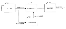
- FIG. 9 shows a configuration of a conventional moving image compression apparatus.
- the moving image data output from the camera unit 101 including the optical system is sent to the moving image compression unit 103 via the preprocessing filter 102, and a compressed moving image stream is output.
- camera control information output separately from the camera unit 101 is sent to the filter control unit 104.
- the filter control unit 104 supplies a filter processing command to the preprocessing filter 102.
- the camera unit 101 performs digital signal processing on a moving image signal picked up via an optical system and outputs it as moving image data which is digital video data. At this time, the camera unit 101 executes many optical system controls and digital signal processing controls such as focus control, zoom control, EV control of aperture and shutter speed, and camera shake correction control, and outputs the control state as camera control information.
- optical system controls and digital signal processing controls such as focus control, zoom control, EV control of aperture and shutter speed, and camera shake correction control, and outputs the control state as camera control information.
- the moving image compression unit 103 compresses the moving image data based on the MPEG2 standard and outputs it as a moving image stream.
- the filter control unit 104 uses the camera control information to determine whether or not the current moving image characteristics are strict for the compression processing of the MPEG2 system and a relatively large amount of compression distortion occurs. If it is determined that a large amount of compression distortion occurs, the filter control unit 104 issues a filter processing command so as to further limit the band of the filter.
- the preprocessing filter 102 receives a filter control command, the preprocessing filter 102 performs a filter process so as to attenuate the high frequency component of the moving image data to be filtered. As a result, since the information amount of the moving image data is reduced, an increase in compression distortion can be prevented.
- the preprocessing filter 102 limits the band of the entire screen to reduce the amount of information as video data of the compressed image. Moreover, the preprocessing filter 102 uniformly filters the entire compressed image (the entire screen). This was also a factor that greatly deteriorated image quality.
- MPEG-4 AVC / H.264 a deblocking filter for removing block distortion is incorporated in the compression mechanism.
- This standard has a new feature different from MPEG2 in that it also reduces block distortion of a reference image during compression processing.
- the standard only specifies that a deblocking filter is provided, and it does not specify how to apply (how to control). At present, no effective control method has been proposed yet.
- the present invention has been made in view of the above problems, and its purpose is MPEG-4 AVC / H. It is to effectively control a deblocking filter as shown in the H.264 standard and to realize high-quality moving image compression while preserving resolution and details while preventing an increase in compression distortion.
- a moving image compression apparatus includes an optical system, an imaging unit that captures a moving image of a subject via the optical system, and outputs moving image data, and at least one of the optical system and the imaging unit at the time of imaging.
- a camera control unit that outputs control information for controlling the operation of the moving image, and a moving image compression unit that compresses the moving image data using a correlation between a compressed image that constitutes the moving image and a reference image.
- a moving image compression unit having a deblocking filter for reducing block distortion of the reference image according to the set deblocking filter strength condition, and a deblocking filter control for setting the deblocking filter strength condition based on the control information
- a stream generation unit that embeds the deblock filter strength condition in the output data after compression.
- the camera control unit may output zoom operation control information for controlling zoom magnification as the control information.
- the camera control unit may output zoom operation control information for controlling a zoom magnification for at least one of electronic zoom and optical zoom.
- the camera control unit may output exposure information for controlling exposure as the control information.
- the camera control unit outputs a plurality of types of control information, and the deblock filter control unit obtains the deblock filter strength condition corresponding to each of the plurality of types of control information, and obtains the plurality of types of deblocks obtained.
- a deblocking filter strength condition that gives the strongest deblocking filter effect among the filter strength conditions may be set.
- the deblock filter control unit may obtain the deblock filter strength condition according to a change speed of the control information.
- the deblock filter control unit obtains a deblock filter strength condition substantially proportional to the change rate when the change rate is increasing. May be.
- the deblocking filter control unit when the change rate of the control information is the change rate of the zoom magnification, determines the de-rate obtained before the change rate starts to decrease. A block filter strength condition may be set, and then the deblock filter strength condition may be relaxed.
- the deblock filter control unit may relax the deblock filter strength condition step by step.
- the camera control unit may output gain information for amplifying the signal amplitude of the moving image captured by the imaging unit as the control information.
- the deblock filter control unit may set the deblock filter strength condition based only on the gain information.
- the moving image compression apparatus further includes a difficulty level detection unit that detects a difficulty level related to compression of the moving image data based on characteristics of the compressed image, and the deblock filter control unit is based on the difficulty level.
- the deblocking filter strength condition may be set based on the basic value determined in this way and the deblocking filter strength condition obtained from the control information.
- the difficulty level detection unit obtains the basic value according to a total sum of variances of the pixel values of the compressed image, and adds the basic value to the deblock filter strength condition obtained from the control information. May be set.
- the moving image compression apparatus prevents the occurrence of block distortion by appropriately setting the deblocking filter strength condition for a video in which the occurrence of block distortion is predicted, and excessively deblocking filter strength condition. Therefore, it is possible to realize high-quality moving image compression without impairing the resolution and detail of the reproduced video.
- FIG. It is a figure which shows the structure of the moving image compression apparatus 100 by embodiment of this invention. It is a figure which shows arrangement
- FIG. It is a graph which shows the relationship between parameter indexA and parameter (alpha). It is a graph which shows the relationship between parameter indexB and parameter (beta). It is a graph which shows the time change of the zoom magnification during the zoom operation from the wide end to the tele end. It is a graph which shows the relationship between the zoom magnification change speed and the filter strength offset by zoom operation. It is a graph which shows an example of the time change of EV information.
- FIG. 1 shows a configuration of a moving image compression apparatus 100 according to the present embodiment.
- the moving image compression apparatus 100 includes an optical system 1, an imaging unit 5, a camera control unit 8, a moving image compression unit 9, a stream generation unit 16, a difficulty level detection unit 17, and a deblock filter control unit 18. I have. Hereinafter, each component will be described in detail, and then processing performed in the moving image compression apparatus 100 will be described.
- the optical system 1 includes a diaphragm 2 and a zoomable lens group 3.
- the optical system 1 is configured to form an image of light from a subject on an image pickup device 4 of an image pickup unit 5 to be described below by a diaphragm 2 and a lens group 3.
- the imaging unit 5 includes an imaging element 4, an amplifier (amplifier) 6, and a signal processing unit 7.
- the imaging unit 5 receives the incident light, captures a subject, and outputs moving image data of the subject.
- the analog output of the image sensor 4 is amplified by the amplifier 6 and supplied to the signal processing unit 7.
- the signal processing unit 7 generates and outputs moving image data based on the received analog signal.
- the moving image data is input to the moving image compression unit 9 and the difficulty level detection unit 17.
- the camera control unit 8 generates a plurality of types of camera control information and instructs each control target.
- the “plurality of types of camera control information” includes, for example, an aperture ratio setting value that controls the aperture 2, an optical zoom setting value that controls the lens group 3, a shutter speed setting value that controls the image sensor 4, An AGC (Auto Gain Control) set value for controlling the amplifier 6 and an electronic zoom set value for the signal processing unit 7 to be controlled.
- the aperture ratio setting value is the aperture 2
- the optical zoom setting value is the lens group 3
- the shutter speed setting value is the image sensor 4
- the AGC setting value is the amplifier 6
- the electronic zoom setting value is the signal processing unit. 7 respectively.
- the camera control information is also supplied to a deblock filter control unit 18 described later. Details of the operation of the deblock filter control unit 18 will be described later.
- the moving image compression unit 9 receives moving image data from the outside, compresses and encodes it, and outputs it.
- the moving image compression unit 9 includes a motion compensation processing unit 10, a compression encoding processing unit 11, a decoding processing unit 12, a deblock filter 13, and reference image memories 14 and 15.
- the motion compensation processing unit 10 receives moving image data and reference image data from the reference image memories 14 and 15, and outputs residual data that is the difference between them.
- the compression encoding processing unit 11 outputs compression encoded data (compressed data) based on the moving image data and the residual data.
- This compressed data is obtained, for example, by compressing and coding data of one picture constituting a moving image.
- the decryption processing unit 12 receives the compressed data, decrypts it once, and outputs it.
- the deblock filter 13 receives the deblock filter strength condition and the decoded image data.
- the deblocking filter 13 performs a block distortion removal process on the decoded image data according to the deblocking filter strength condition.
- the reference image memories 14 and 15 temporarily store image data of reference images.
- the stream generation unit 16 receives the compressed data of each picture, and generates and outputs a compressed stream including the compressed data of a plurality of pictures.
- the difficulty level detection unit 17 receives the moving image data and outputs a deblock filter strength condition basic value.
- the deblock filter control unit 18 receives the deblock filter strength condition basic value and camera control information, and outputs the deblock filter strength condition.
- the deblocking filter strength condition is input to the deblocking filter 13 and the stream generation unit 16.
- the basic operation of the moving image compression apparatus 100 is as follows.
- the image sensor 4 captures an image formed on the image sensor 4 by the optical system 1.
- the signal processing unit 7 performs AD conversion and digital processing on the signal, and outputs it as moving image data which is digital data.
- the camera control unit 8 executes zoom control including control of the optical zoom state of the lens group 3 using the optical zoom setting signal and control of the electronic zoom magnification of the signal processing unit 7 using the electronic zoom setting signal. To do. Further, the camera control unit 8 sets the aperture 2 using the aperture ratio setting signal, sets the shutter speed of the image pickup device 4 using the shutter speed setting signal, and adjusts the exposure amount of the image pickup device 4 comprehensively. An exponent (value) (EV) control is also executed. If the camera control unit 8 determines that the aperture ratio is sufficiently large and the shutter speed is sufficiently slow by EV control and the exposure is insufficient and the amplitude of the analog output of the image sensor 4 is small, the AGC setting signal is output.
- AGC control is also carried out to increase the gain of the amplifier 6 and compensate for the amplitude of the moving image signal.
- the moving image data obtained from the optical system 1 and the imaging unit 5 always controlled in an appropriate state by the camera control unit 8 is supplied to the moving image compression unit 9, and the moving image compression unit 9 executes a compression encoding process.
- the moving image compression unit 9 has a moving image pressure mechanism that performs moving image compression that can use the correlation between the input image and the reference image.
- the MPEG-4 AVC / H It is assumed that it is operating according to the H.264 standard.
- I picture A picture that is compression-coded using only the data of one picture.
- An I picture can be decoded with only that data. That is, the compression of all the constituent blocks of the compressed image is completed within the range of the compressed image, and is also called an intra slice.
- P picture A picture obtained by performing inter-picture prediction in one direction from a past picture and coding a difference value.
- the P picture is compression-coded with reference to any one picture of the I picture or the other P picture displayed before in time. Therefore, a P picture can be decoded with reference to an I picture or other P picture as a reference picture.
- B picture A picture in which a difference value is encoded by performing two-way inter-picture prediction from past and future pictures.
- the B picture is compression-encoded with reference to at least two pictures of a picture displayed before in time and a picture displayed after time.
- the picture to be referred to is an I picture, a P picture, or a past B picture.
- a B picture that is allowed to be referenced from the B picture is referred to as a reference B picture.
- the moving image compression unit 9 also performs reordering processing that rearranges compressed images in the order of processing. However, since this is essentially irrelevant to the present invention, it is omitted from the configuration of FIG. Description will be made assuming that moving image data is input to the moving image compression unit 9 in the order of compression processing.
- the motion compensation processing unit 10 pauses and only the compression coding processing unit 11 receives the moving image data as a compressed video.
- the compression encoding processing unit 11 performs MPEG-4 AVC / H.
- processing such as orthogonal transformation, quantization, and high-efficiency encoding is executed, and compressed data is output.
- the compressed data is decoded by the decoding processing unit 12 and supplied to the deblocking filter 13 as decoded image data.
- the deblocking filter 13 performs block distortion removal processing on the decoded image data in accordance with the deblocking filter strength condition given from the deblocking filter control unit 18, and the reference image data obtained as a result is stored in the reference image memory 14 or the reference image memory 15.
- the stream generation unit 16 receives compressed data as an input, embeds various additional information such as header attachment and deblock filter strength conditions, and outputs a compressed stream according to the standard.
- MPEG-4 AVC / H For example, MPEG-4 AVC / H.
- a stream is configured in units of NAL units, and various types of additional information are stored in a NAL unit called a picture parameter set or various types of SEI depending on the contents, or are added to the head portion of the compressed data of each slice. Embedded directly in the slice header.
- the deblock filter strength condition is embedded in the slice header in units of slices.
- the motion compensation processing unit 10 When moving image data to be a P picture, B picture, or reference B picture is input to the moving image compression unit 9, the motion compensation processing unit 10 inputs the compressed image data, the reference image memory 14, and the reference image memory 15.
- the motion vector search is executed using the reference image data stored in the image, a predicted image is generated, a difference from the compressed image is obtained, and the residual data is transmitted to the compression encoding processing unit 11.
- the operations of the compression encoding processing unit 11, the stream generation unit 16, the decoding processing unit 12, and the deblocking filter 13 for the residual data are the same as in the case of the I picture described above, but the reference picture is not obtained only in the case of the B picture. Therefore, the decoding processing unit 12 and the deblocking filter 13 are not operating.
- the deblock filter 13 is a filter introduced to remove block distortion generated by the compression processing of the compression encoding processing unit 11.
- the processing content is MPEG-4 AVC / H.
- the H.264 standard is defined in detail according to the case, and the deblocking filter 13 of this embodiment also operates according to the definition.
- FIG. 2 shows an arrangement of 8 horizontal pixels including a certain block boundary in the decoded image output from the decoding processing unit 12.
- Pixels p3 to p0 belong to block P
- pixels q0 to q3 belong to block Q
- the boundary between pixel p0 and pixel q0 is a block boundary.
- Block distortion appears as a step at this block boundary.
- the “step” means a difference in pixel values (for example, luminance value, color value). In particular, if there is a difference that can be perceived by human vision, humans will feel the presence of “block distortion”.
- the deblock filter 13 processes a maximum of this 8 pixel range.
- the deblocking filter 13 first determines a parameter ⁇ and a parameter ⁇ in order to determine the content of the deblocking process for each block boundary.
- the parameters ⁇ and ⁇ are used as criteria for determining whether to apply deblocking processing to block boundaries. Further, as will be described in detail with reference to Equations 4 to 6, the parameters ⁇ and ⁇ are also used as criteria for determining the specific contents of the deblocking process.
- the inventors of the present application adopt a “deblock filter strength condition” as one of the conditions for determining the important parameters ⁇ and ⁇ related to the deblocking process. The decision was made using control information. This will be specifically described below.
- FIG. 3A is a graph showing the relationship between the parameter indexA and the parameter ⁇ .
- the deblocking filter 13 obtains the parameter ⁇ from the parameter indexA according to the graph of FIG. 3A.
- the deblocking filter 13 obtains the parameter indexB from the qPav and the deblocking filter strength condition FilterOffsetB according to (Equation 2) for the parameter ⁇ .
- Equation 2) indexB qPav + FilterOffsetB
- FIG. 3B is a graph showing the relationship between the parameter indexB and the parameter ⁇ .
- the deblocking filter 13 obtains the parameter ⁇ from the parameter indexB according to the graph of FIG. 3B.
- the deblocking filter 13 applies the obtained parameters ⁇ and ⁇ to the following (Equation 3), and determines whether or not (Equation 3) is satisfied.
- Equation 1 it is understood that the size of the parameter indexA changes depending on the size of the parameter FilterOffsetA. As apparent from FIG. 3A, the magnitude of the parameter ⁇ also changes according to the magnitude of the parameter indexA.
- the deblocking filter 13 does not perform the deblocking process on the 8 pixels in FIG. On the other hand, when (Equation 3) is satisfied, the deblocking filter 13 performs a deblocking process.
- the deblocking process When the deblocking process is performed, the detailed contents of the deblocking process proceed to the condition judgment classified in more detail, and the parameter ⁇ , the parameter ⁇ , and the values of the respective pixels in FIG.
- the filter coefficient and the range of pixels to be processed are determined.
- pixel values of the pixels p 0 , p 1 , and p 2 are converted into p ′ 0 , p 2 by deblocking filter processing. The description will be made assuming that “ 1” and “p” 2 are updated.
- the pixel values p ′ 0 , p ′ 1 , and p ′ 2 are based on the pixel values p 0 , p 1 , p 2 , p 3 , q 0 , and q 1 (Expression 5 ).
- the pixel values p ′ 0 , p ′ 1 , and p ′ 2 are filters based on (Equation 6) based on the pixel values p 0 , p 1 , p 2 , and q 1.
- (Equation 5) is calculated using more pixel values than the pixel to be calculated, and the influence of surrounding pixels is stronger. It is a filtering process to receive.
- (Equation 6) the values of the original pixels are used as they are except for p ′ 0 and are not updated.
- (Equation 5) updates not only p ′ 0 but also p ′ 1 and p ′ 2. It is a process that is called.
- Equation 4 if the values of ⁇ and ⁇ are large, (Equation 4) is satisfied at more block boundaries, and as a result, a broader and more extensive filtering process is applied according to (Equation 5).
- Equation 3 indicates that the larger the values of the parameter ⁇ and the parameter ⁇ , the easier the deblocking filter processing is performed. Further, even in the condition judgment classified in more detail, as is clear from (Equation 4), it is defined that a filter having a stronger intensity is adopted in a wider range as the values of the parameters ⁇ and ⁇ are larger.
- the deblock filter strength conditions FilterOffsetA and FilterOffsetB given to the deblock filter 13 from the outside of the deblock filter 13 can offset the strength adjustment of the deblock processing. It is.
- the difficulty level detection unit 17 inputs the moving image data, extracts the feature of the compressed image to be processed by the moving image compression unit 9, and determines the degree of difficulty of the compression processing of the moving image compression unit 9 from the feature. Then, the difficulty level detection unit 17 estimates the amount of block distortion that occurs and provides the deblock filter strength condition basic value to the deblock filter control unit 18. As a result, for example, it is possible to set the deblocking filter strength condition more tightly with respect to block distortion due to video-specific features that occur synergistically with block distortion that occurs depending on the camera control operation.
- the sum of variances is obtained based on each pixel value of the image to be compressed, and a value from ⁇ 6 to 0 is set according to the value as a basic condition for deblocking filter strength conditions.
- Adopt as a value.
- the difficulty level detection unit 17 may always output a fixed value as the deblock filter strength condition basic value.
- the deblock filter control unit 18 determines the deblock filter strength condition using the camera control information transmitted from the camera control unit 8 and the deblock filter strength condition basic value.
- the deblock filter strength condition basic value In this embodiment, an example in which at least one of zoom information, EV information, and AGC information is used as camera control information will be described. It is assumed that both pieces of information are expressed as numerical values. Processing using each information will be described in the following order.
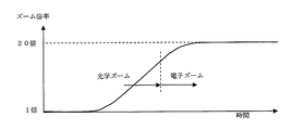
- the zoom information included in the camera control information indicates the zoom magnification of each frame.
- FIG. 4 is a graph showing the time change of the zoom magnification during the zoom operation from the wide end to the tele end.
- FIG. 4 shows a state in which the camera control unit 8 continues the control from the optical zoom to the electronic zoom and finally stops at the 20 ⁇ zoom.
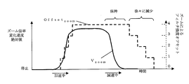
- the deblocking filter control unit 18 obtains the zoom magnification change rate VZOOM, and determines the filter strength offset OffsetZOOM as the degree of contribution to the deblocking filter strength condition based on the value of VZOOM.
- the zoom magnification change speed VZOOM is defined by the magnification change amount / time change amount.
- FIG. 5 is a graph showing the relationship between the zoom magnification change speed and the filter strength offset by the zoom operation.
- the deblock filter control unit 18 determines the value of OffsetZOOM so as to be substantially proportional to VZOOM during the rising period of VZOOM, that is, during acceleration. Note that the OffsetZOOM graph is stepped because it is an integer value from 0 to 4.
- the deblocking filter control unit 18 holds the value of OffsetZOOM before a certain period during the falling period of VZOOM, that is, when the vehicle starts to decelerate, and then gradually decreases the value of OffsetZOOM so as to decrease, for example, stepwise. To decide.
- the block distortion occurs at the same position on the screen regardless of the movement of the subject. Therefore, the block distortion is visually very conspicuous, and the filter strength is insufficient only by the automatic strength adjustment of the deblocking filter 13.
- the reason why block distortion is visually noticeable will be explained in more detail. It is the boundary of the block that generates block distortion. Since the position of the block is fixed in the entire screen, the block boundary is always present at the same position in the screen. No matter how the image (subject) moves, the block boundary position within one screen does not change. Therefore, during zooming, the block distortion does not move with the subject even though the image apparently moves in the radial direction, so that the block distortion is very noticeable visually.
- the deblock filter control unit 18 determines the value of OffsetZOOM, so that the insufficient deblock filter strength can be appropriately compensated.
- a large block distortion often occurs because the state of the image changes abruptly. This is particularly noticeable when the zoom speed is high.
- the deblock filter control unit 18 holds the value of OffsetZOOM corresponding to the zoom speed even immediately after the zoom operation is completed. Therefore, block distortion can be removed appropriately. Note that when the deblocking filter strength is suddenly changed, an unstable image may appear that the autofocus mechanism vibrates. However, even in such a case, the deblocking filter control unit 18 gradually reduces the value of OffsetZOOM, thereby preventing an adverse effect that appears as an unstable image.
- the deblock filter control unit 18 determines the zoom magnification change speed from the zoom magnification.
- the camera control unit 8 may output a flag indicating the zoom period as zoom information, and the deblock filter control unit 18 may adopt a uniform and constant OffsetZOOM value during the period indicated by the flag. This can exhibit a sufficient effect when the zoom speed is low.
- the zoom magnification and zoom magnification change speed shown in FIGS. 4 and 5 have been described as being processed for a zoom magnification combining optical zoom and electronic zoom. However, as a configuration using only the optical zoom magnification, the value of OffsetZOOM during the optical zoom operation may be held during the electronic zoom. Since the occurrence of block distortion does not become larger during the electronic zoom than during the optical zoom, the effect can be obtained even if the processing during the electronic zoom is simplified.
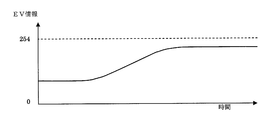
- the EV information included in the camera control information of the present embodiment is numerical information expressed by an integer from 0 to 254 that is approximately proportional to the EV value obtained from the F value of the aperture 2 (FIG. 1) and the shutter speed. is there. It is assumed that EV information is transmitted from the camera control unit 8 for each frame.
- FIG. 6 is a graph showing an example of time change of EV information.
- FIG. 6 shows that the numerical value of the EV information is increased by reducing the aperture 2 when the illuminance of the subject increases and the overexposure occurs.
- the deblock filter control unit 18 obtains the EV information change rate VEV, and determines the filter strength offset OffsetEV as a degree to be contributed to the deblock filter strength condition based on the value of VEV.
- FIG. 7 is a graph showing the relationship between the EV information change rate (absolute value) and the filter strength offset according to the exposure information.
- the method of determining OffsetEV for VEV by the deblocking filter control unit 18 is exactly the same as in the zoom operation shown in FIG. 5, and only the value of OffsetEV is different.
- the filter strength is insufficient only by automatically adjusting the filter strength of the deblocking filter 13.
- the deblock filter control unit 18 determines the value of OffsetEV using the change rate of the EV information, so that the insufficient deblock filter strength can be appropriately compensated. It is exactly the same as the zoom operation described above that the effect of preventing the effect of abruptly changing the block distortion or deblock filter strength immediately after the exposure control operation is exhibited.
- a method of obtaining the average luminance of the compressed image by the difficulty level detection unit 17 is also conceivable.
- the exposure state is estimated from the image after the exposure amount is adjusted by automatic exposure control, it is very difficult to realize appropriate control.
- the brightness ratio in the screen changes by panning slowly without changing the brightness of the subject, it is impossible to correctly determine the exposure status from the image data. It cannot be controlled.
- deblock filter strength setting that is difficult to control from video data is easily and appropriately realized.
- the deblock filter control unit 18 determines the Offset EV value from the EV information.
- the normal aperture 2 is not so much because automatic exposure control is set to operate with shutter speed priority. If it does not change, the OffsetEV value may be determined only by the shutter speed information.
- the Offset EV value may be determined using only aperture ratio setting information of the aperture 2 or F value information. In either case, the same effects as described above can be obtained. Further, there is no necessity for defining the EV value, and parameters expressing exposure states with different definitions may be used, and the same effect can be obtained.
- the AGC information included in the camera control information of the present embodiment means a set gain for the amplifier 6 (FIG. 1), and is numerical information expressed in numerical values in units of 3 dB. It is assumed that AGC information is transmitted from the camera control unit 8 for each frame.
- Table 1 shows the correspondence between AGC information and filter strength offset OffsetAGC.
- the deblocking filter control unit 18 determines the filter strength offset OffsetAGC by AGC control as a degree to be contributed to the deblocking filter strength condition according to Table 1.
- the camera control unit 8 increases the gain so that the amplifier 6 amplifies the analog output of the image sensor 4, the moving image data has already deteriorated the S / N ratio and becomes a noticeable noise, and block distortion occurs. However, it is relatively inconspicuous. Therefore, unlike the case of the EV information described above, the effect is small even if the change rate of the AGC information is obtained and the OffsetAGC is obtained.
- Table 1 showing the relationship between AGC information and OffsetAGC is an example.
- the value of the AGC information may be substituted, so that the Offset AGC may be specified in the function format.
- the AGC information is expressed by a numerical value of 3 dB unit, this unit is also an example. It may be smaller than 3 dB unit.
- the deblock filter control unit 18 uses the determined three types of filter strength offset values and the deblock filter strength condition basic value given from the difficulty level detection unit 17 to supply the deblock filter 13 with the deblock filter control unit 18 (FIG. 1).
- Block filter strength conditions FilterOffsetA and FilterOffsetB are determined.
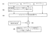
- FIG. 8 is a flowchart showing a rule for determining the deblocking filter strength requirement.
- step S1 the value of OffsetZOOM, the value of OffsetEV, and the value of OffsetAGC are specified.
- step S2 when the compressed image is an I picture, the deblock filter control unit 18 sets the values of OffsetZOOM and OffsetEV to 0.
- step S3 the deblock filter control unit 18 compares the value of OffsetZOOM, the value of OffsetEV, and the value of OffsetAGC, and selects the maximum value among them.
- step S4 the deblock filter control unit 18 adds the deblock filter strength condition basic value specified separately to the selected value, and in step S5, the addition result is the value of the deblock filter strength conditions FilterOffsetA and FilterOffsetB. Determine as.
- the three offset values obtained from the camera control information are all intended to correct block distortion caused by the degree of difficulty of the motion compensation processing of the motion compensation processing unit 10.
- the degree of difficulty in motion compensation tends not to be additively affected by these three factors, but to be dominated by the most influential factors. Therefore, appropriate block distortion removal can be realized by adopting the maximum value of the three offset values.
- OffsetAGC affects not only block distortion caused by motion compensation but also block distortion caused by the degree of difficulty of the compression encoding processing unit 11. Therefore, in the case of an I picture, only the value of OffsetAGC is left, and the side effect of excessive deblocking processing can be prevented by changing the value of OffsetZOOM and the value of OffsetEV to 0.
- the basic value of the deblocking filter strength condition obtained by the difficulty level detection unit 17 is to remove block distortion caused by the degree of difficulty of the compression coding processing unit 11 such as the amount of information of the compressed video. It is what. This is not related to the state of camera control or the degree of difficulty of the motion compensation process, and one of them does not become dominant, but has an additive effect on block distortion. Therefore, appropriate block distortion removal can be realized by adding the deblock filter strength condition basic value to the offset value selected and determined from the camera information.
- the deblock filter 13 When the compressed video is a B picture, the deblock filter 13 is paused as described above. However, the deblock filter control unit 13 sets the B block so that the deblock filter strength condition can be used during reproduction. Also in the case of a picture, the deblock filter strength condition is determined and supplied to the stream generation unit 16.
- the deblock filter strength conditions FilterOffsetA and FilterOffsetB are the same values, but different values may be used. If FilterOffsetB is made small, the process of the deblocking filter 13 becomes difficult to be applied when the amount of information inside the block is large. Therefore, by adjusting specific numerical value settings and ratio settings of FilterOffsetA and FilterOffsetB, it is possible to adapt to the performance unique to the apparatus such as the S / N ratio and resolution of the optical system 1 and the imaging unit 5.
- the deblocking filter control unit sets FilterOffsetA and FilterOffsetB from the camera control information as reinforcement when the deblocking strength is insufficient for the automatic deblocking filter strength adjustment shown in FIGS. 3A and 3B. And explained the operation to make up for the shortage. Conversely, when the deblocking effect is too effective in the automatic deblocking filter strength adjustment, it may be used as a suppression thereof.
- the deblock filter control unit 18 controls the deblock filter 13 using the zoom operation control information, it is possible to reliably remove particularly remarkable block distortion that occurs in the zoom operation.
- the maximum value of the block filter strength condition obtained from each of the plurality of elements of the camera control information is employed, so that the strength of the deblock filter 13 is not excessively applied and the resolution and details of the reference image are not impaired.
- the degree of strength of the deblocking filter 13 can be set to an appropriate value, and even block distortion that occurs immediately after the end of the optical system control can be removed.
- the deblock filter control unit 18 sets the deblock filter strength condition without using the zoom operation control information and the exposure information in the camera control information. Accordingly, it is possible to prevent a side effect of impairing the resolution by applying an excessive deblocking filter to the I picture which is not easily influenced by the camera control.
- this makes it possible to control the deblocking filter more tightly when the zoom speed at which particularly large block distortion is likely to occur or when the exposure amount change speed is high. That is, the deblocking filter strength condition can be controlled only in the case of moving image compression based on the correlation with the reference image in which the occurrence of block distortion depending on the camera control operation is particularly significant.
- deblocking processing strength is insufficient and block distortion does not stand out. On the contrary, it does not lose excessive resolution and detail, and always achieves proper block distortion removal, greatly improving the quality of the reference image. Can be improved. Since the residual data of the motion compensation processing unit 10 is reduced and the quantization index qP is improved by improving the image quality of the reference image, the image quality of the compressed video can be greatly improved comprehensively. In addition, since the deblocking filter strength condition optimally controlled in the present embodiment is embedded in the compressed stream by the stream generation unit 16, the optimum deblocking process at the time of recording can be reproduced even during reproduction, and high image quality can be realized. .
- the moving image compression apparatus controls the strength of the deblocking filter processing applied to the reference image by using the camera control information and always realizes appropriate block distortion removal, MPEG-4 AVC / H.
- the present invention can be applied to an apparatus for compressing a moving image having a mechanism for removing block distortion from a reference image, such as H.264 standard.
Abstract
Priority Applications (2)
| Application Number | Priority Date | Filing Date | Title |
|---|---|---|---|
| JP2009550483A JP5232175B2 (ja) | 2008-01-24 | 2009-01-23 | 動画像圧縮装置 |
| US12/864,248 US8532199B2 (en) | 2008-01-24 | 2009-01-23 | Dynamic image compression device |
Applications Claiming Priority (2)
| Application Number | Priority Date | Filing Date | Title |
|---|---|---|---|
| JP2008-013302 | 2008-01-24 | ||
| JP2008013302 | 2008-01-24 |
Publications (1)
| Publication Number | Publication Date |
|---|---|
| WO2009093472A1 true WO2009093472A1 (fr) | 2009-07-30 |
Family
ID=40900981
Family Applications (1)
| Application Number | Title | Priority Date | Filing Date |
|---|---|---|---|
| PCT/JP2009/000269 WO2009093472A1 (fr) | 2008-01-24 | 2009-01-23 | Dispositif de compression d'image dynamique |
Country Status (3)
| Country | Link |
|---|---|
| US (1) | US8532199B2 (fr) |
| JP (1) | JP5232175B2 (fr) |
| WO (1) | WO2009093472A1 (fr) |
Cited By (3)
| Publication number | Priority date | Publication date | Assignee | Title |
|---|---|---|---|---|
| JP2018113699A (ja) * | 2011-06-28 | 2018-07-19 | ソニー株式会社 | テレビジョン装置、携帯電話機、再生装置、カメラ、および画像処理方法 |
| WO2018186430A1 (fr) * | 2017-04-06 | 2018-10-11 | パナソニック インテレクチュアル プロパティ コーポレーション オブ アメリカ | Dispositif et procédé de codage, dispositif et procédé de décodage |
| US11095888B2 (en) | 2017-04-06 | 2021-08-17 | Panasonic Intellectual Property Corporation Of America | Encoder, decoder, encoding method, and decoding method |
Families Citing this family (8)
| Publication number | Priority date | Publication date | Assignee | Title |
|---|---|---|---|---|
| JP2013524659A (ja) * | 2010-04-07 | 2013-06-17 | リニア アルジェブラ テクノロジーズ リミテッド | ハンドヘルド及びモバイル用途に適した低減された記憶容量及び処理要求を有するブロードキャストビデオレコーダ |
| JP5492058B2 (ja) * | 2010-11-19 | 2014-05-14 | 株式会社メガチップス | 画像処理装置 |
| US9161046B2 (en) | 2011-10-25 | 2015-10-13 | Qualcomm Incorporated | Determining quantization parameters for deblocking filtering for video coding |
| CN102547296B (zh) * | 2012-02-27 | 2015-04-01 | 开曼群岛威睿电通股份有限公司 | 移动估计加速电路、移动估计方法及环路滤波加速电路 |
| TWI666915B (zh) * | 2012-04-06 | 2019-07-21 | 日商Jvc建伍股份有限公司 | Image coding device, image coding method, and recording medium storing image coding program |
| US20140254659A1 (en) | 2013-03-11 | 2014-09-11 | Mediatek Inc. | Video coding method using at least evaluated visual quality and related video coding apparatus |
| CN114342369A (zh) * | 2019-09-02 | 2022-04-12 | 北京字节跳动网络技术有限公司 | 用于视频编解码的色度去方块调谐 |
| JP7359653B2 (ja) * | 2019-11-06 | 2023-10-11 | ルネサスエレクトロニクス株式会社 | 動画像符号化装置 |
Citations (4)
| Publication number | Priority date | Publication date | Assignee | Title |
|---|---|---|---|---|
| JP2006513633A (ja) * | 2003-01-10 | 2006-04-20 | トムソン ライセンシング | エラー隠蔽中に生成されるアーチファクトをスムージングするデコーダ装置及び方法 |
| JP2006254370A (ja) * | 2005-03-14 | 2006-09-21 | Canon Inc | 画像処理装置、方法、コンピュータプログラム及び記憶媒体 |
| JP2007129369A (ja) * | 2005-11-01 | 2007-05-24 | Matsushita Electric Ind Co Ltd | 画像再生装置およびその方法 |
| JP2007184870A (ja) * | 2006-01-10 | 2007-07-19 | Toshiba Corp | 情報処理装置及び情報処理装置の動画像復号方法 |
Family Cites Families (20)
| Publication number | Priority date | Publication date | Assignee | Title |
|---|---|---|---|---|
| US5337088A (en) * | 1991-04-18 | 1994-08-09 | Matsushita Electric Industrial Co. Ltd. | Method of correcting an image signal decoded in block units |
| JP3360191B2 (ja) | 1994-02-28 | 2002-12-24 | 富士通株式会社 | 画像符号化装置及び画像符号化方法 |
| US5926209A (en) | 1995-07-14 | 1999-07-20 | Sensormatic Electronics Corporation | Video camera apparatus with compression system responsive to video camera adjustment |
| JPH09121354A (ja) * | 1995-10-25 | 1997-05-06 | Oki Electric Ind Co Ltd | ループフィルタ制御方法、動きベクトル検出方法及びループフィルタ制御回路 |
| JPH114361A (ja) | 1997-06-13 | 1999-01-06 | Hitachi Ltd | 画像情報処理方法とそれを利用したディジタル撮像装置 |
| JP2917988B1 (ja) | 1998-03-16 | 1999-07-12 | 日本電気株式会社 | 動画像符号化装置のプレフィルタ |
| US6735337B2 (en) * | 2001-02-02 | 2004-05-11 | Shih-Jong J. Lee | Robust method for automatic reading of skewed, rotated or partially obscured characters |
| JP3849461B2 (ja) * | 2001-06-07 | 2006-11-22 | ソニー株式会社 | 撮像装置及び撮像方法 |
| US6895122B2 (en) * | 2001-06-25 | 2005-05-17 | Eastman Kodak Company | Method and system for determining DCT block boundaries |
| JP2003224751A (ja) | 2002-01-29 | 2003-08-08 | Canon Inc | 画像処理装置、画像処理システム、画像処理方法、記憶媒体、及びプログラム |
| WO2004030369A1 (fr) * | 2002-09-27 | 2004-04-08 | Videosoft, Inc. | Codage et decodage video en temps reel |
| JP4324844B2 (ja) * | 2003-04-25 | 2009-09-02 | ソニー株式会社 | 画像復号化装置及び画像復号化方法 |
| US7733380B1 (en) * | 2005-07-19 | 2010-06-08 | Maxim Integrated Products, Inc. | Method and/or architecture for controlling encoding parameters using integrated information from camera ISP |
| US9479794B2 (en) * | 2005-11-10 | 2016-10-25 | Freescale Semiconductor, Inc. | Resource efficient video processing via prediction error computational adjustments |
| WO2007089803A2 (fr) * | 2006-01-31 | 2007-08-09 | Thomson Licensing | Procédés et appareils de filtrage spatio-temporel fondé sur les contours |
| JP4747975B2 (ja) | 2006-07-14 | 2011-08-17 | ソニー株式会社 | 画像処理装置および方法、プログラム、並びに、記録媒体 |
| US8204129B2 (en) * | 2007-03-27 | 2012-06-19 | Freescale Semiconductor, Inc. | Simplified deblock filtering for reduced memory access and computational complexity |
| JP2008263529A (ja) * | 2007-04-13 | 2008-10-30 | Sony Corp | 符号化装置、符号化方法、符号化方法のプログラム及び符号化方法のプログラムを記録した記録媒体 |
| US20080298472A1 (en) * | 2007-06-04 | 2008-12-04 | Texas Instruments Incorporated | Throughput Performance When Applying Deblocking Filters On Reconstructed Image Frames |
| CN103124354B (zh) * | 2007-09-28 | 2016-01-20 | 杜比实验室特许公司 | 处理视频信息 |
-
2009
- 2009-01-23 US US12/864,248 patent/US8532199B2/en not_active Expired - Fee Related
- 2009-01-23 JP JP2009550483A patent/JP5232175B2/ja active Active
- 2009-01-23 WO PCT/JP2009/000269 patent/WO2009093472A1/fr active Application Filing
Patent Citations (4)
| Publication number | Priority date | Publication date | Assignee | Title |
|---|---|---|---|---|
| JP2006513633A (ja) * | 2003-01-10 | 2006-04-20 | トムソン ライセンシング | エラー隠蔽中に生成されるアーチファクトをスムージングするデコーダ装置及び方法 |
| JP2006254370A (ja) * | 2005-03-14 | 2006-09-21 | Canon Inc | 画像処理装置、方法、コンピュータプログラム及び記憶媒体 |
| JP2007129369A (ja) * | 2005-11-01 | 2007-05-24 | Matsushita Electric Ind Co Ltd | 画像再生装置およびその方法 |
| JP2007184870A (ja) * | 2006-01-10 | 2007-07-19 | Toshiba Corp | 情報処理装置及び情報処理装置の動画像復号方法 |
Cited By (8)
| Publication number | Priority date | Publication date | Assignee | Title |
|---|---|---|---|---|
| JP2018113699A (ja) * | 2011-06-28 | 2018-07-19 | ソニー株式会社 | テレビジョン装置、携帯電話機、再生装置、カメラ、および画像処理方法 |
| WO2018186430A1 (fr) * | 2017-04-06 | 2018-10-11 | パナソニック インテレクチュアル プロパティ コーポレーション オブ アメリカ | Dispositif et procédé de codage, dispositif et procédé de décodage |
| US11095888B2 (en) | 2017-04-06 | 2021-08-17 | Panasonic Intellectual Property Corporation Of America | Encoder, decoder, encoding method, and decoding method |
| CN114040201A (zh) * | 2017-04-06 | 2022-02-11 | 松下电器(美国)知识产权公司 | 解码方法和编码方法 |
| CN114040200A (zh) * | 2017-04-06 | 2022-02-11 | 松下电器(美国)知识产权公司 | 编码装置和解码装置 |
| CN114040200B (zh) * | 2017-04-06 | 2023-05-16 | 松下电器(美国)知识产权公司 | 编码装置和解码装置 |
| CN114040201B (zh) * | 2017-04-06 | 2023-05-16 | 松下电器(美国)知识产权公司 | 解码方法和编码方法 |
| US11863741B2 (en) | 2017-04-06 | 2024-01-02 | Panasonic Intellectual Property Corporation Of America | Encoder, decoder, encoding method, and decoding method |
Also Published As
| Publication number | Publication date |
|---|---|
| JP5232175B2 (ja) | 2013-07-10 |
| US8532199B2 (en) | 2013-09-10 |
| JPWO2009093472A1 (ja) | 2011-05-26 |
| US20100296588A1 (en) | 2010-11-25 |
Similar Documents
| Publication | Publication Date | Title |
|---|---|---|
| JP5232175B2 (ja) | 動画像圧縮装置 | |
| US7903733B2 (en) | Adaptive filtering to enhance video encoder performance | |
| JP2009004920A (ja) | 画像符号化装置および画像符号化方法 | |
| US8009963B2 (en) | Adaptive filtering to enhance video bit-rate control performance | |
| US8229004B2 (en) | Image signal processing apparatus with code amount control for inter-frame and intra-frame encoding | |
| US9633415B2 (en) | Systems and methods for improving video stutter in high resolution progressive video | |
| US20130182177A1 (en) | Systems and methods for improving video stutter in high resolution progressive video | |
| KR100893419B1 (ko) | 촬상 장치 및 촬상 방법 | |
| US20070188634A1 (en) | Imaging apparatus | |
| JP2010199656A (ja) | 動画撮像装置 | |
| US20090225193A1 (en) | Image processing apparatus | |
| US8040947B2 (en) | Bitrate control device for controlling bitrate of video data | |
| JP6092690B2 (ja) | 撮像装置およびその制御方法 | |
| JP2007028598A (ja) | 圧縮符号化装置及び圧縮符号化方法 | |
| JP2006166108A (ja) | 撮像装置および撮像制御方法 | |
| JP4612897B2 (ja) | 画像処理装置 | |
| JP2012231302A (ja) | 画像符号化装置、画像符号化方法、プログラム、および記録媒体 | |
| JP2006345255A (ja) | 撮像装置 | |
| JPH05268586A (ja) | 画像圧縮装置 |
Legal Events
| Date | Code | Title | Description |
|---|---|---|---|
| 121 | Ep: the epo has been informed by wipo that ep was designated in this application |
Ref document number: 09704866 Country of ref document: EP Kind code of ref document: A1 |
|
| ENP | Entry into the national phase |
Ref document number: 2009550483 Country of ref document: JP Kind code of ref document: A |
|
| WWE | Wipo information: entry into national phase |
Ref document number: 12864248 Country of ref document: US |
|
| NENP | Non-entry into the national phase |
Ref country code: DE |
|
| 122 | Ep: pct application non-entry in european phase |
Ref document number: 09704866 Country of ref document: EP Kind code of ref document: A1 |