EP0838561B9 - Lüftungselement für Dächer mit Abdichtorgan - Google Patents
Lüftungselement für Dächer mit Abdichtorgan Download PDFInfo
- Publication number
- EP0838561B9 EP0838561B9 EP97118190A EP97118190A EP0838561B9 EP 0838561 B9 EP0838561 B9 EP 0838561B9 EP 97118190 A EP97118190 A EP 97118190A EP 97118190 A EP97118190 A EP 97118190A EP 0838561 B9 EP0838561 B9 EP 0838561B9
- Authority
- EP
- European Patent Office
- Prior art keywords
- layer
- sealing
- ventilating
- layers
- element according
- Prior art date
- Legal status (The legal status is an assumption and is not a legal conclusion. Google has not performed a legal analysis and makes no representation as to the accuracy of the status listed.)
- Expired - Lifetime
Links
Images


Classifications
-
- F—MECHANICAL ENGINEERING; LIGHTING; HEATING; WEAPONS; BLASTING
- F24—HEATING; RANGES; VENTILATING
- F24F—AIR-CONDITIONING; AIR-HUMIDIFICATION; VENTILATION; USE OF AIR CURRENTS FOR SCREENING
- F24F7/00—Ventilation
- F24F7/02—Roof ventilation
-
- E—FIXED CONSTRUCTIONS
- E04—BUILDING
- E04D—ROOF COVERINGS; SKY-LIGHTS; GUTTERS; ROOF-WORKING TOOLS
- E04D1/00—Roof covering by making use of tiles, slates, shingles, or other small roofing elements
- E04D1/36—Devices for sealing the spaces or joints between roof-covering elements
-
- E—FIXED CONSTRUCTIONS
- E04—BUILDING
- E04D—ROOF COVERINGS; SKY-LIGHTS; GUTTERS; ROOF-WORKING TOOLS
- E04D13/00—Special arrangements or devices in connection with roof coverings; Protection against birds; Roof drainage; Sky-lights
- E04D13/17—Ventilation of roof coverings not otherwise provided for
- E04D13/174—Ventilation of roof coverings not otherwise provided for on the ridge of the roof
- E04D13/176—Ventilation of roof coverings not otherwise provided for on the ridge of the roof formed by flexible material suitable to be rolled up
Definitions
- the invention relates to a ventilation element for roofs, with one in the ridge, hip or ridge area arranged fan cap, the at least one elastic Sealing member is assigned.
- a ventilation element for roofs, with an inside Fan flap to be arranged in the ridge, hip or ridge area and with at least one to the edge area the sealing flap connecting the fan flap is known from DE 296 08 830 U1.
- the sealing element has at least two superimposed, in the direction of the longitudinal axis of the fan flap running, flat sealing strips.
- Everyone Sealing strip has a variety of essentially transverse to the direction of the longitudinal axis, elastic horizontal stripes.
- the object of the invention is therefore a ventilation element to create of the type mentioned at which ensures an optimal seal and that is evenly and homogeneously any roofing material adapts.
- a ventilation element according to the invention solved that mentioned in claim 1
- the multilayer element is designed as a bar. That in Ventilation element arranged in the ridge and ridge area enables air circulation and air exchange throughout the roof structure, which for example Condensation water formation and the resulting damage be prevented.
- the multi-layer element prevents through its homogeneous sealing respectively Adaptation to every roofing material Entry of driving rain and flying snow and so on.
- An embodiment of the ventilation element is preferred, which is characterized in that the material Surface material is and that several layers of the surface material arranged one above the other are. So the multilayer element is made up of several preferably from the same, elastic properties layers made of material educated. A multilayer element is preferred that is made up of three layers of sheet material is. The top edges of the sheet material will be placed on top of each other as strips and connected to each other, for example welded. By welding the layers of the multilayer element into one Sealing body, the properties of the sheet material, especially the elasticity in advantageous Exploited way, namely that the multilayer element is highly adaptable has, whereby a uniform seal against ensures the entry of rain and snow is.
- an embodiment of the ventilation element suggested at least two layers of the surface material to form the multilayer element with the incisions and / or the free cuts.
- the incisions are production-related very simple and therefore inexpensive recoverable. They also have the advantage that they realize small distances from each other, whereby the adaptability significantly increased and nevertheless the sealing function of the ventilation element in the assembled condition is guaranteed.
- the incisions can be designed as fine cuts, thereby the adaptability of the ventilation element can be further improved. Another The advantage of the incisions is that in the multilayer element penetrating rain or condensation immediately on the lower layer of the multi-layer element and derived on the roofing material becomes.
- the incisions are based on one Introduced into the long side of the multilayer element, so that between two side by side Incisions a stripe is formed, the southern Ventilation curtains (insect screens) is similar.
- a multi-layer element is preferred for the ventilation element, where the incisions and / or free cuts across, especially at right angles, to Longitudinal extension of the multilayer element arranged are. It is also conceivable that their course serrated or is wavy. By aligning the Incisions will increasingly ensure that the Shape of the multi-layer element even when assembled preserved.
- an embodiment of the ventilation element preferred, which is characterized by that the cuts and / or cuts of the individual Layers run at an angle to each other. It is possible that, for example, the incisions of the upper Position transverse to the longitudinal extension of the multilayer element are arranged and the incisions the other layers below with the incisions and / or clearing the top layer enclose an angle so that the incisions and / or free cuts of the individual layers - with one Consideration of the multilayer element from above cross.
- the between the cuts and / or free cuts horizontal stripes of the individual layers are different broadly trained.
- the width of the Stripes within a layer are the same, though the stripe width varies from layer to layer can be.
- An embodiment is preferred of the ventilation element, which is characterized by that the stripe width of the top layer is smaller than that of the middle layer and that the stripe width the lower layer is larger than that of the middle and top layer.
- the stripe width is - when considering the multilayer element graded from above and is with every layer wider.
- “below” here is the side of the multilayer element. referred to on the roofing material rests.
- the "top" side of the Multilayer element is accordingly the side which is opposite the lower side.
- An embodiment of the ventilation element is also preferred, where the length of the strips of individual layers are of different sizes. Through the shows different lengths of the individual layers the multilayer element has different thicknesses.
- An embodiment of the ventilation element is preferred, which is characterized in that the Strip length of the top layer is shorter than that the middle layer and that the strip length of the lower layer is longer than that of the middle and top layer. The individual layers are therefore scale-like one above the other.
- an embodiment of the ventilation element preferred where the thickness of each Layers is different in size.
- Particularly preferred is an embodiment that is characterized by that the top layer is thicker than that middle layer and that the lower layer is thinner than the middle and top layer. This ensures that the top layer is the ones underneath Layers depressed due to their greater mass or holds down so that this itself both in the recesses and in the elevations of the roofing material.
- Ventilation element which is characterized in that a fan cap with at least one multilayer element is formed in one piece. That is it possible, the ventilation element, i.e. cap and sealing strip, to wind up into a roll, on the one hand Can be stored or transported to save space and on the other hand very easy to install is. When laying, the roll is simply on the Rolled out roof over a ridge slat, positioned and attached. The time spent laying the ventilation element is therefore very low.
- multilayer element and / or the multilayer element one-piece fan cap made of plastic, preferably polyvinyl chloride, polypropylene, Polyethylene, or preferably of flexible metal, in particular aluminum.
- FIG. 1 shows a ventilation element 1, which in Ridge, hip or ridge area can be used.
- the Ventilation element 1 has a band-shaped fan cap 3 with a ceiling wall 5 on the two end regions 4 and 6 each have a sealing member 7 is assigned.
- Air passage openings 8 arranged on the Function is discussed in more detail below.
- the Sealing member 7 is made of an elastic material existing multilayer element 10 is formed.
- a slat holder 11 is attached to a ridge beam 9, which has a U-shaped profile 13, in that a brush bar 15 is introduced.
- rafters, not shown, will also be battens, of which only the slats 17 are shown here are appropriate.
- On the slats 17 are bricks 19 hung and held by these.
- the fan cap 3 lies with its top wall 5 the ridge bar 15 on and by means of each other spaced fastening means, not shown here, for example nail-like pins, Clamps or the like attached to the ridge 15. Furthermore, 15 Ridge brackets 21 attached, the fixing and Attach ridge tiles 23 serve. The ridge tiles are arranged on the fan cap 3 cone-shaped spacers 25 worn respectively are due to this. It can too bracket-like spacers may be provided Have contact edges on which the ridge tiles 23 are concerned or supported and the press down the fan cap 3, making it elastic is deformed. Such spacers are known, so that it is not discussed in more detail here becomes.
- the sealing members 7 are arranged, the in the embodiment shown in Figure 1 as a single separable from the fan cap 3 Parts are formed.
- the sealing elements 7 are provided with a clamping rail 26 which the fan cap pushed on or put on is.
- the sealing members 7 can in one advantageous embodiment of the invention in one piece be formed with the fan cap 3. Under "One piece” is to be understood to mean that the ventilation element is formed from a material.
- the ready-to-install functional part i.e.
- the sealing organs 7 serve the irregularly large, between the Top 27 of the brick 19 and bottom 29 to close the ridge tile 23 column in such a way that on the one hand air circulation in the Ridge area is possible and that on the other hand a Ingress of rain or snow is prevented.
- the multilayer element 10 is in a side view shown unfolded (upper figure) and here has three made of a sheet material manufactured layers 31, 33 and 35.
- the built in Condition of layers 31 to one above the other 35 are strip-shaped with one another on a longitudinal side 37 connected, for example welded, glued or the like.
- Particularly advantageous is to make the multilayer element from one piece inject or extrude (see Figure 7). in the installed state of the multilayer element 10 lie the layers 31 to 35 one above the other, the layer 35 on the top 27 of the brick 19 rests.
- layer 35 is therefore used as the lower layer, the layer 33 as the middle layer and the layer 31 as called upper layer.
- the layers 31 to 35 have in this embodiment, the same length L on, but different thicknesses.
- the top layer 31 shows the lowest and the middle position 33 the greatest thickness. Basically it is too possible, the layers of the multilayer element the same to train strong or thick.
- the single ones Layers of the multilayer element 10 have air permeable Incisions 39 that are spaced to each other and transverse to the longitudinal extent of the sealing member 7 are arranged.
- the incisions 39 are from the long side 41 of the layers 31, 33 and 35 introduced into this, whereby strips 43 are formed be in the area of the long side 41 of the layers are not connected.
- the stripes show 43 of the upper layer 31 the same width.
- the Incisions 39 are made in a punching or cutting process before joining the individual layers together in the overlying locations respectively introduced into the ventilation element 1. Becomes in this machining process material on the Cutting point removed, so free cuts are formed. In the case of incisions, no material is used ablated.
- Air flow 45 flows from the eaves in the roof structure to the ridge.
- the air flow 45 passes through the air outlet openings 8 of the band-shaped fan cap 3 through and into the space 47, the between the ventilation element 1 and the ridge tiles 23 trains.
- the airflow arrives from there 45 through a gap between the bottom 29 of the ridge tile 23 and the top 27 the brick 19 is formed, to the outside.
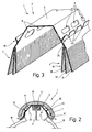
- FIG. 2 shows a side view of the ridge area of the roof according to Figure 1 with another embodiment of the ventilation element 1. Same parts are provided with the same reference numerals, so that insofar referred to the description of Figure 1 can be. In the following, only the Differences entered.
- the fan cap 3 is with the sealing elements arranged at the end regions 4 and 6 7 connected in one piece.
- the ridge tile 23, which rests here on the ceiling wall 5, is by spacers arranged on the fan cap 3 25 worn here in one piece the fan cap are designed in the form of webs. and extend in the longitudinal direction of the fan cap (see Figure 3).
- a perspective detail drawing the fan cap 3 according to FIG. 2 is in Figure 3 shown.
- In the spacers 25 are Recesses 49 introduced, on their function in following is discussed.
- the one in the ridge area rising air flow 45 passes through the passage openings 8 in the space 47, the like described above - arranged below the ridge tile 23 and from there in the spacers 25 arranged open-edge recesses 49 outward.
- Recesses 49 can also be recesses and / or Through openings in the web-shaped spacers here 25 may be provided.
- the fan cap 3 and the sealing members 7 of the ventilation element 1 in one piece trained with each other.
- the air openings 8 have a rectangular shape here Contour on. The one flowing from the eaves to the ridge Air passes through the air passage openings 8 and the recesses arranged in the spacers 25 49 to the outside.
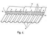
- Figure 4 shows the perspective view Ridge area of the roof according to Figure 1.
- the bricks 19 have a wavy shape Surface on which the smooth Multilayer element 10 creates such that sealing the ridge area against rain and snow is guaranteed.
- the so-called Wave valleys lay through one One or free cut produced strips 43 of the individual layers close to each other and to the surface of the brick 19 while they are on the Spacing the wave crests of the brick, that is, the space between two strips is enlarged. From the layers of the multilayer element 10 is only the upper layer 31 in FIG. 4 recognizable.
- the bricks 19 can be another Have surface shape that the Multilayer element 10 is applied in a suitable manner. Regardless of the design of the brick 19 is the desired by the ventilation element 1 Sealing against rain and snow or the like and air circulation in the ridge area of the Roof. In Figure 4 is from First air emerging from the roof is indicated by arrows.
- Figures 5a to 5d show four embodiments the ventilation element 1 in side view.
- the figures 5a and 5b each show a one-piece design Ventilation element 1.
- Under "one piece” is to understand that the ceiling wall 5 and to the End regions 4 and 6 arranged sealing members 7 are inextricably linked, for example welded or in a spraying or extrusion process manufactured. It is also possible to use the sealing elements to spray onto the ventilation element.
- the layers 31, 33 and 35 of the multilayer element 10 of the ventilation element shown in Figure 5a essentially both the same length as also the same thickness.
- Embodiment of the ventilation element differs from that shown in Figure 5a Ventilation element only in that the individual Layers 31, 33 and 35 different lengths have, the upper layer 31 longest and the lower layer 35 is the shortest. This puts itself in the assembled state of the ventilation element Layer 31 over the layers 33 and 35 below and covers them.
- FIG. 5c shows a further embodiment of the Ventilation element 1, the multilayer element 10 only has two layers 31 and 33.
- the first Layer 31 of the multilayer element 10 is extended from the Top wall 5 of the fan cap 3 is formed.
- the layer 33 is designed as a separate part and is at position 31 in the manner described above or attached to the fan cap 3.
- the Ventilation element 1 shown in Figure 5d a multi-layer element 10 with a total of three layers that are connected to each other, for example welded, glued or the like, the Layers 33 and 35 are individual parts and layer 31 in one piece with the fan cap 3 of the ventilation element connected is.
- FIG 6 shows a plan view of a section a further embodiment of a mat-like Surface material formed ventilation element 1 and parts of the sealing member 7. parts, which correspond to those in Figure 7 are with provided with the same reference numerals so that Reference is made to Figure 7.
- the ventilation element 1 has air passage openings 8 on that are formed here in the form of elongated holes are. Incisions are made in the multilayer element 10 39 introduced, which start from the long side 41, whereby strips 43 are formed.
- the Stripes 43 have the same length and are here just for clarity, of different lengths shown. This should make it clear that the Incisions 39 cut through the long side 41, see above that the tab-like strips 43 are formed.
- the pictures below show the individual Layers of the multilayer element 10.
- Stripe 43 shown different lengths.
- the Strip width B3 of the upper layer 31 is larger than the strip width B2 of the middle layer 33, where the width B2 of the strips 43 of the middle layer 33 is greater than the strip width B1 of the lower one Location 35.
- Figure 8 shows a side view and a top view to the individual layers of a further embodiment of the sealing member designed as a multilayer element 10.
- the multilayer element 10 is in the upper Representation (side view) shown spread apart, that is, in the installed state of the Multi-layer element overlying layers form an angle with each other. Same Parts are provided with the same reference symbols, see above that referred to the description of Figure 7 becomes.
- the lower layer 35 has a length L1, which is greater than the length L2 of the middle layer 33 and the length L3 of the upper layer 31. As from FIG 8, the upper layer 31 has the smallest length on.
- the thickness D1 of the bottom layer 35 corresponds here to the thickness D2 of the middle layer 33.
- the thickness D3 of the upper layer 31 is less than that of the middle or the lower layer.
- layers 31, 33 and 35 of the multilayer element 10 arranged like a comb Incisions 39, causing loose on one side Strips 43 are formed.
- the incisions 39 are starting from the long side 41 into the individual Layers brought.
- the strips 43 of each Layers of different widths the width the stripe is the same within one layer.
- the width B3 of the strips of the top layer 31 is smaller than the width B2 of the strips of the middle one Layer 33 and the width B1 of the strips of the lower one Layer 35.
- the width B1 of the strips of the lower layer 35 have the greatest width here.
- FIG. 9 shows a perspective view of the Multi-layer element 10 according to FIG. 8.
- the layers 31, 33 and 35 are on their long side 37 by means of a Clamping rail 51 connected to each other, the Multi-layer element 10 or the clamping rail 10 in a recording of the ceiling wall 5 of the Fan cap 3 can be inserted.
- the multi-layer element 10 is here as a so-called pull-in sealing strip educated. Looking at the figure 9 it is clear that the strips 43 of each Layers are arranged offset from each other, whereby if the individual strips are in contact with one Deepening or raising a brick the Spaces between two strips of a layer through one or more strips of an underlying one Location will be covered, creating the ridge area of the roof against the entry of flying snow and driving rain is sealed.
- Figure 10 shows a perspective view of a another embodiment of the multilayer element 10 (top illustration) and a top view of the individual layers (lower figure). That in Figure 10 Multi-layer element shown differs from that in Figure 7 only in that the strips of the individual layers have different widths.
- the width B3 of the strips of the top layer 31 is less than the width B2 of the strips of middle layer 33, the width B2 being smaller is the width B1 of the strips of the bottom layer 35.
- the layers 31, 33 and 35 are on their long sides 37 with each other by means of the clamping rail 51 connected.
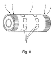
- FIG. 11 shows the ventilation element according to FIG 6 rolled up. Due to the compact Shape of the ventilation element, it is possible without it to carry special effort. With that the Transport of the ventilation element significantly simplified.
- the sealing member 7 can with a fan cap 3, which is formed in one piece, a smaller material thickness have than the ceiling wall 5. This on the one hand, the fan cap 3 in the area reinforced by this on the ridge 15 rests, and the sealing member 7 keeps on the other hand its elasticity.
- Another embodiment of the ventilation element according to the invention is characterized in that the ventilation element is made of several materials.
- the ceiling wall 5 made of metal and the sealing element 7 be made of a plastic. It is also possible to use at least one layer of the Multi-layer element 10 formed sealing member To manufacture metal.
- the sealing element designed as a multilayer element 7 has great adaptability due to the incisions 39 on all roofing materials. Furthermore, one is made of plastic Multi-layer element 10 weatherproof, whereby its functionality is guaranteed even after long use is. Through the superimposed Layers 31, 33 and 35 are the result of the mooring the strip formed on the roofing material Gaps sealed from the underlying layer, causing the entry of rain and snow is prevented.
- the number of layers of the multilayer element is variable and can be more than three be.
- a multi-layer element with less than three Layers are shown in Figure 5c.
- the multi-layer element is also used as a multi-layer flap, multi-layer sealing tape, Multi-layer sealing strips, multi-layer compartment seal, Multi-layer scale seal and Designated multi-cut position.
- the ventilation element also has the advantage on that the sealing elements with the roofing material do not need to be glued so that the ventilation element easy to lay in any weather is. Nevertheless, due to the attachment by the Dead weight of the sealing elements on the roofing material a good pressure and thus a secure seal the ridge and hip area of the roof. Because no preparatory work must be carried out for the gluing process, for example cleaning the roofing material from Dust, material residues or the like, and that the pressing of the glued sealing elements omitted, are the costs for a roof covering reduced.
Description
- Figur 1
- einen Querschnitt durch einen Firstbereich des Daches eines Gebäudes mit einem Lüftungselement,
- Figur 2
- einen Querschnitt durch den Firstbereich des Daches mit einer anderen Ausführungsform des Lüftungselements,
- Figur 3
- eine perspektivische Ansicht des Lüftungselements gemäß Figur 2,
- Figur 4
- eine perspektivische Ansicht eines Dachabschnitts im Firstbereich,
- Figuren 5a bis 5d
- eine Seitenansicht weiterer Ausführungsformen des Lüftungselements,
- Figur 6
- eine Draufsicht auf einen Ausschnitt einer weiteren Ausführungsform des Lüftungselements sowie drei Teilansichten eines Abdichtorgans,
- Figur 7
- eine Seitenansicht und Draufsicht auf eine Ausführungsform des Abdichtorgans,
- Figur 8
- eine weitere Ausführungsform des Abdichtorgans in Seitenansicht und eine Draufsicht auf die einzelnen Teile des Abdichtorgans,
- Figur 9
- eine perspektivische Ansicht des Abdichtorgans gemäß Figur 8,
- Figur 10
- eine Ansicht einer weiteren Ausführungsform des Abdichtorgans in perspektivischer Darstellung und eine Draufsicht auf die einzelnen Lagen des Abdichtorgans und
- Figur 11
- eine perspektivische Ansicht eines aufgerollten Lüftungselements.
Claims (15)
- Lüftungselement (1) für Dächer, mit einer in First-, Walm- oder Gratbereich angeordneten Lüfterkappe (3), der mindestens ein elastisches Abdichtorgan (7) zugeordnet ist, das als aus elastischem Material bestehendes, kammartig angeordnete Einschnitte (39) und/oder Freischnitte aufweisendes Mehrlagenelement (10) ausgebildet ist, dadurch gekennzeichnet, daß die Breite der zwischen den Einschnitten (39) und/oder Freischnitten liegenden Streifen (43) einer Lage (31,33,35) gegenüber der Breite der zwischen den Einschnitten (39) und/oder Freischnitten liegenden Streifen (43) einer anderen Lage (31,33,35) unterschiedlich groß ausgebildet ist.
- Lüftungselement nach Anspruch 1, dadurch gekennzeichnet, daß das Mehrlagenelement (10) ein Mehrlagenlappen, insbesondere ein Mehrlagendichtungsband, ist.
- Lüftungselement nach einem der vorhergehenden Ansprüche, dadurch gekennzeichnet, daß das elastische Material Flächenmaterial ist und daß mehrere Lagen (31,33,35) des Flächenmaterials übereinanderliegend angeordnet sind.
- Lüftungselement nach Anspruch 3, dadurch gekennzeichnet, daß zumindest zwei Lagen (31;33;35) des Flächenmaterials zur Ausbildung des Mehrlagenelementes (10) mit den Einschnitten (39) und/oder den Freischnitten versehen sind.
- Lüftungselement nach einem oder mehreren der vorhergehenden Ansprüche, dadurch gekennzeichnet, daß die Einschnitte und/oder Freischnitte quer, insbesondere rechtwinklig, zur Längserstreckung des Mehrlagenelementes (10) angeordnet sind.
- Lüftungselement nach einem oder mehreren der vorhergehenden Ansprüche, dadurch gekennzeichnet, daß die Einschnitte und/oder Freischnitte der einzelnen Lagen (31,33,35) winklig zueinander verlaufen.
- Lüftungselement nach einem der vorhergehenden Ansprüche, dadurch gekennzeichnet, daß die Streifenbreite (B3) einer oberen Lage (31) des Abdichtorgans kleiner ist als die einer mittleren Lage (33) des Abdichtorgans und daß die Streifenbreite (B1) einer unteren Lage (35) des Abdichtorgans größer ist als die der mittleren und oberen Lage.
- Lüftungselement nach einem der vorhergehenden Ansprüche, dadurch gekennzeichnet, daß die Länge (L1,L2,L3) der Streifen (43) der einzelnen Lagen (31,33,35) unterschiedlich groß ist.
- Lüftungselement nach einem der vorhergehenden Ansprüche, dadurch gekennzeichnet, daß die Streifenlänge (L3) einer oberen Lage (31) des Abdichtorgans kürzer ist als die einer mittleren Lage (33) des Abdichtorgans und daß die Streifenlänge (L1) einer unteren Lage (35) des Abdichtorgans länger ist als die der mittleren und oberen Lage.
- Lüftungselement nach einem der vorhergehenden Ansprüche, dadurch gekennzeichnet, daß die Dicke (D1,D2,D3) der einzelnen Lagen (31,33,35) unterschiedlich groß ist.
- Lüftungselement nach einem der vorhergehenden Ansprüche, dadurch gekennzeichnet, daß eine obere Lage (31) des Abdichtorgans dicker ist als eine mittlere Lage (33) des Abdichtorgans und daß eine untere Lage (35) des Abdichtorgans dünner ist als die mittlere und obere Lage.
- Lüftungselement nach einem oder mehreren der vorhergehenden Ansprüche, dadurch gekennzeichnet, daß das Lüftungselement (1) als flexibles, insbesondere von einer Rolle abwickelbares Mehrlagen-Dichtungsband ausgebildet ist.
- Lüftungselement nach einem oder mehreren der vorhergehenden Ansprüche, dadurch gekennzeichnet, daß die Lüfterkappe (3) mit mindestens einem Mehrlagenelement (10) einstückig ausgebildet ist.
- Lüftungselement nach einem oder mehreren der vorhergehenden Ansprüche, dadurch gekennzeichnet, daß das Mehrlagenelement (10) mindestens einem seitlichen Endbereich (4,6) der Lüfterkappe (3) zugeordnet ist.
- Lüftungselement nach einem oder mehreren der vorhergehenden Ansprüche, dadurch gekennzeichnet, daß das Mehrlagenelement (10) beziehungsweise die das Mehrlagenelement (10) einstückig aufweisende Lüfterkappe (3) aus Kunststoff oder Metall gefertigt ist.
Applications Claiming Priority (2)
| Application Number | Priority Date | Filing Date | Title |
|---|---|---|---|
| DE19643591 | 1996-10-22 | ||
| DE19643591A DE19643591B4 (de) | 1996-10-22 | 1996-10-22 | Lüftungselement für Dächer mit Abdichtorgan |
Publications (4)
| Publication Number | Publication Date |
|---|---|
| EP0838561A2 EP0838561A2 (de) | 1998-04-29 |
| EP0838561A3 EP0838561A3 (de) | 1999-01-27 |
| EP0838561B1 EP0838561B1 (de) | 2003-06-25 |
| EP0838561B9 true EP0838561B9 (de) | 2004-01-02 |
Family
ID=7809461
Family Applications (1)
| Application Number | Title | Priority Date | Filing Date |
|---|---|---|---|
| EP97118190A Expired - Lifetime EP0838561B9 (de) | 1996-10-22 | 1997-10-20 | Lüftungselement für Dächer mit Abdichtorgan |
Country Status (4)
| Country | Link |
|---|---|
| EP (1) | EP0838561B9 (de) |
| AT (1) | ATE243799T1 (de) |
| DE (2) | DE19643591B4 (de) |
| DK (1) | DK0838561T3 (de) |
Families Citing this family (6)
| Publication number | Priority date | Publication date | Assignee | Title |
|---|---|---|---|---|
| US6213868B1 (en) * | 1999-07-12 | 2001-04-10 | Cor-A-Vent, Inc. | Roof ventilator with movable member to prevent entry of moisture |
| FR2847661B1 (fr) * | 2002-11-25 | 2005-02-25 | Invent Or | Bouche d'extraction de gaz a membrane flexible de regulation |
| ES2275049T3 (es) * | 2003-08-21 | 2007-06-01 | Blowitex Vliesstoffe International Gmbh | Banda de material en forma de tira para una cubierta de caballete y/o de arista de tejado. |
| DE102005022940A1 (de) * | 2005-05-19 | 2006-11-23 | Lafarge Roofing Components Gmbh & Co. Kg | First- und Gratabdeckung |
| GB2451458B (en) * | 2007-07-31 | 2012-03-28 | Manthorpe Building Products Ltd | Barrier members |
| DE102018111745A1 (de) * | 2018-05-16 | 2019-11-21 | Bosig Baukunststoffe Gmbh | Lüftungsband für den First oder Grat eines Daches |
Family Cites Families (10)
| Publication number | Priority date | Publication date | Assignee | Title |
|---|---|---|---|---|
| DE2256675C3 (de) * | 1972-11-18 | 1975-05-15 | Braas & Co Gmbh, 6000 Frankfurt | Dichtungsstreifen für eine Firstoder Gratabdeckung |
| DE2707384A1 (de) * | 1977-02-21 | 1978-08-24 | Herbst Karl Heinz | Lueftungsfirstkappe fuer dachziegel und pfannendaecher |
| DE3306837A1 (de) * | 1983-02-26 | 1984-10-04 | Braas & Co Gmbh, 6000 Frankfurt | First- oder gratabdeckung fuer mit dacheindeckungsplatten eingedeckte daecher |
| EP0428775B1 (de) * | 1989-11-21 | 1997-05-07 | Norm A.M.C. Ag | Vorrichtung zur Hinterlüftung von Dächern |
| DE4123313C2 (de) * | 1991-07-13 | 1995-03-30 | Oskar Fleck | Firstentlüftungselement |
| DE4130181C1 (en) * | 1991-09-11 | 1993-04-22 | Oskar 4354 Datteln De Fleck | Ridge or edge section covering element - includes central fixing to ridge slot and edge regions which cover the gap between ridge slot and two roof covering plates |
| DE4226817A1 (de) * | 1992-08-13 | 1994-02-24 | Norm Amc Ag | Lüfterkappe zur Hinterlüftung von Dächern |
| DE29501242U1 (de) * | 1995-01-27 | 1995-03-16 | Gehring Manfred Dr | Rollbarer Dichtungsstreifen für eine First- und/oder Gratabdeckung |
| DE19602979C1 (de) * | 1996-01-27 | 1997-04-17 | Norm Amc Ag | Lüftungselement für Dächer mit Abdichtorgan |
| DE29608830U1 (de) * | 1996-05-17 | 1996-08-14 | Norm Amc Ag | Lüftungselement für Dächer |
-
1996
- 1996-10-22 DE DE19643591A patent/DE19643591B4/de not_active Expired - Fee Related
-
1997
- 1997-10-20 DK DK97118190T patent/DK0838561T3/da active
- 1997-10-20 EP EP97118190A patent/EP0838561B9/de not_active Expired - Lifetime
- 1997-10-20 DE DE59710340T patent/DE59710340D1/de not_active Expired - Fee Related
- 1997-10-20 AT AT97118190T patent/ATE243799T1/de not_active IP Right Cessation
Also Published As
| Publication number | Publication date |
|---|---|
| DE19643591A1 (de) | 1998-04-23 |
| ATE243799T1 (de) | 2003-07-15 |
| EP0838561B1 (de) | 2003-06-25 |
| DK0838561T3 (da) | 2003-10-20 |
| EP0838561A2 (de) | 1998-04-29 |
| DE19643591B4 (de) | 2007-08-30 |
| EP0838561A3 (de) | 1999-01-27 |
| DE59710340D1 (de) | 2003-07-31 |
Similar Documents
| Publication | Publication Date | Title |
|---|---|---|
| EP0341343B1 (de) | Dichtungsstreifen für eine First- oder Gratabdeckung | |
| AT392113B (de) | Unterspannbahn fuer eine unterhalb der dacheindeckungsplatten eines schraegdaches anbringbare belueftete unterspannhaut | |
| EP0724048B1 (de) | Rollbarer Dichtungsstreifen für eine First- und/oder Gratabdeckung | |
| EP0791699B1 (de) | Aufrollbares First- und Gratbelüftungselement | |
| EP0838561B9 (de) | Lüftungselement für Dächer mit Abdichtorgan | |
| DE4404150C1 (de) | Lüftungsband | |
| EP0786568B1 (de) | Lüftungselement für Dächer | |
| EP0428775B1 (de) | Vorrichtung zur Hinterlüftung von Dächern | |
| DE3630982C2 (de) | ||
| EP1534907B1 (de) | First- oder gratband | |
| EP1013845B1 (de) | First- oder Gratenlüftungselement | |
| DE4441296C2 (de) | Universallüfter mit plissierten Seitenteilen in gespritzter Ausführung | |
| DE10015094C1 (de) | Lüftungsstreifen für Dächer | |
| EP0807726A2 (de) | Lüftungselement für Dächer | |
| DE10161637C1 (de) | Dachdämmplatte | |
| EP3569789B1 (de) | Lüftungsband für den first oder grat eines daches | |
| EP0952273B1 (de) | Dachrinnen-Laubfänger | |
| EP1508655B1 (de) | Streifenförmige Materialbahn für eine First- und/oder Gratabdeckung | |
| DE202004020247U1 (de) | Wohndachfenster | |
| EP1074673B1 (de) | Flexibles Traufenabdichtungselement | |
| DE102005029361B3 (de) | First- oder Gratabdeckung | |
| EP0707120A1 (de) | Dichtungsstreifen für First- und/oder Gratabdeckungen und Verfahren zu seiner Herstellung | |
| EP0854253A1 (de) | Extrudierter Universallüfter mit plissierten Seitenteilen | |
| DE202005010024U1 (de) | First- oder Gratabdeckelement | |
| DE202004011155U1 (de) | Lüftungselement für Dächer |
Legal Events
| Date | Code | Title | Description |
|---|---|---|---|
| PUAI | Public reference made under article 153(3) epc to a published international application that has entered the european phase |
Free format text: ORIGINAL CODE: 0009012 |
|
| AK | Designated contracting states |
Kind code of ref document: A2 Designated state(s): AT BE CH DE DK FI FR GB IE IT LI LU NL SE |
|
| AX | Request for extension of the european patent |
Free format text: AL;LT;LV;RO;SI |
|
| PUAL | Search report despatched |
Free format text: ORIGINAL CODE: 0009013 |
|
| AK | Designated contracting states |
Kind code of ref document: A3 Designated state(s): AT BE CH DE DK ES FI FR GB GR IE IT LI LU MC NL PT SE |
|
| AX | Request for extension of the european patent |
Free format text: AL;LT;LV;RO;SI |
|
| 17P | Request for examination filed |
Effective date: 19990322 |
|
| AKX | Designation fees paid |
Free format text: AT BE CH DE DK FI FR GB IE IT LI LU NL SE |
|
| AXX | Extension fees paid |
Free format text: LT PAYMENT 19990322;LV PAYMENT 19990322;SI PAYMENT 19990322 |
|
| RAP1 | Party data changed (applicant data changed or rights of an application transferred) |
Owner name: BWK-DACHZUBEHOER GMBH |
|
| RAP1 | Party data changed (applicant data changed or rights of an application transferred) |
Owner name: RICKERT, HUBERT |
|
| 17Q | First examination report despatched |
Effective date: 20020709 |
|
| GRAH | Despatch of communication of intention to grant a patent |
Free format text: ORIGINAL CODE: EPIDOS IGRA |
|
| RAP1 | Party data changed (applicant data changed or rights of an application transferred) |
Owner name: LIMACO UNTERNEHMENSBERATUNG AKTIENGESELLSCHAFT |
|
| GRAH | Despatch of communication of intention to grant a patent |
Free format text: ORIGINAL CODE: EPIDOS IGRA |
|
| GRAA | (expected) grant |
Free format text: ORIGINAL CODE: 0009210 |
|
| AK | Designated contracting states |
Designated state(s): AT BE CH DE DK FI FR GB IE IT LI LU NL SE |
|
| AX | Request for extension of the european patent |
Extension state: LT LV SI |
|
| REG | Reference to a national code |
Ref country code: GB Ref legal event code: FG4D Free format text: NOT ENGLISH |
|
| REG | Reference to a national code |
Ref country code: CH Ref legal event code: EP |
|
| REG | Reference to a national code |
Ref country code: IE Ref legal event code: FG4D Free format text: GERMAN |
|
| REF | Corresponds to: |
Ref document number: 59710340 Country of ref document: DE Date of ref document: 20030731 Kind code of ref document: P |
|
| REG | Reference to a national code |
Ref country code: CH Ref legal event code: NV Representative=s name: SULZER MANAGEMENT AG |
|
| REG | Reference to a national code |
Ref country code: SE Ref legal event code: TRGR |
|
| GBT | Gb: translation of ep patent filed (gb section 77(6)(a)/1977) |
Effective date: 20031008 |
|
| LTIE | Lt: invalidation of european patent or patent extension |
Effective date: 20030625 |
|
| PLBQ | Unpublished change to opponent data |
Free format text: ORIGINAL CODE: EPIDOS OPPO |
|
| PLBI | Opposition filed |
Free format text: ORIGINAL CODE: 0009260 |
|
| ET | Fr: translation filed | ||
| PLAX | Notice of opposition and request to file observation + time limit sent |
Free format text: ORIGINAL CODE: EPIDOSNOBS2 |
|
| 26 | Opposition filed |
Opponent name: SCHEFFLER GMBH & CO. KG Effective date: 20040325 |
|
| NLR4 | Nl: receipt of corrected translation in the netherlands language at the initiative of the proprietor of the patent | ||
| NLR1 | Nl: opposition has been filed with the epo |
Opponent name: SCHEFFLER GMBH & CO. KG |
|
| PLAX | Notice of opposition and request to file observation + time limit sent |
Free format text: ORIGINAL CODE: EPIDOSNOBS2 |
|
| PLBP | Opposition withdrawn |
Free format text: ORIGINAL CODE: 0009264 |
|
| PLBB | Reply of patent proprietor to notice(s) of opposition received |
Free format text: ORIGINAL CODE: EPIDOSNOBS3 |
|
| PLBD | Termination of opposition procedure: decision despatched |
Free format text: ORIGINAL CODE: EPIDOSNOPC1 |
|
| PLBM | Termination of opposition procedure: date of legal effect published |
Free format text: ORIGINAL CODE: 0009276 |
|
| STAA | Information on the status of an ep patent application or granted ep patent |
Free format text: STATUS: OPPOSITION PROCEDURE CLOSED |
|
| 27C | Opposition proceedings terminated |
Effective date: 20041209 |
|
| NLR2 | Nl: decision of opposition |
Effective date: 20041209 |
|
| PGFP | Annual fee paid to national office [announced via postgrant information from national office to epo] |
Ref country code: DK Payment date: 20050913 Year of fee payment: 9 |
|
| PGFP | Annual fee paid to national office [announced via postgrant information from national office to epo] |
Ref country code: NL Payment date: 20050914 Year of fee payment: 9 |
|
| PGFP | Annual fee paid to national office [announced via postgrant information from national office to epo] |
Ref country code: FI Payment date: 20050915 Year of fee payment: 9 |
|
| PGFP | Annual fee paid to national office [announced via postgrant information from national office to epo] |
Ref country code: IE Payment date: 20050920 Year of fee payment: 9 |
|
| PGFP | Annual fee paid to national office [announced via postgrant information from national office to epo] |
Ref country code: LU Payment date: 20051005 Year of fee payment: 9 |
|
| PGFP | Annual fee paid to national office [announced via postgrant information from national office to epo] |
Ref country code: BE Payment date: 20051014 Year of fee payment: 9 |
|
| PGFP | Annual fee paid to national office [announced via postgrant information from national office to epo] |
Ref country code: DE Payment date: 20051025 Year of fee payment: 9 |
|
| PGFP | Annual fee paid to national office [announced via postgrant information from national office to epo] |
Ref country code: GB Payment date: 20060914 Year of fee payment: 10 |
|
| PG25 | Lapsed in a contracting state [announced via postgrant information from national office to epo] |
Ref country code: IE Free format text: LAPSE BECAUSE OF NON-PAYMENT OF DUE FEES Effective date: 20061020 Ref country code: FI Free format text: LAPSE BECAUSE OF NON-PAYMENT OF DUE FEES Effective date: 20061020 |
|
| PG25 | Lapsed in a contracting state [announced via postgrant information from national office to epo] |
Ref country code: DK Free format text: LAPSE BECAUSE OF NON-PAYMENT OF DUE FEES Effective date: 20061031 |
|
| PGFP | Annual fee paid to national office [announced via postgrant information from national office to epo] |
Ref country code: IT Payment date: 20061031 Year of fee payment: 10 |
|
| PG25 | Lapsed in a contracting state [announced via postgrant information from national office to epo] |
Ref country code: NL Free format text: LAPSE BECAUSE OF NON-PAYMENT OF DUE FEES Effective date: 20070501 Ref country code: DE Free format text: LAPSE BECAUSE OF NON-PAYMENT OF DUE FEES Effective date: 20070501 |
|
| NLV4 | Nl: lapsed or anulled due to non-payment of the annual fee |
Effective date: 20070501 |
|
| REG | Reference to a national code |
Ref country code: IE Ref legal event code: MM4A |
|
| BERE | Be: lapsed |
Owner name: *LIMACO UNTERNEHMENSBERATUNG A.G. Effective date: 20061031 |
|
| PGFP | Annual fee paid to national office [announced via postgrant information from national office to epo] |
Ref country code: SE Payment date: 20060919 Year of fee payment: 10 |
|
| PGFP | Annual fee paid to national office [announced via postgrant information from national office to epo] |
Ref country code: CH Payment date: 20071115 Year of fee payment: 11 Ref country code: AT Payment date: 20071121 Year of fee payment: 11 |
|
| PGFP | Annual fee paid to national office [announced via postgrant information from national office to epo] |
Ref country code: FR Payment date: 20071114 Year of fee payment: 11 |
|
| EUG | Se: european patent has lapsed | ||
| GBPC | Gb: european patent ceased through non-payment of renewal fee |
Effective date: 20071020 |
|
| PG25 | Lapsed in a contracting state [announced via postgrant information from national office to epo] |
Ref country code: LU Free format text: LAPSE BECAUSE OF NON-PAYMENT OF DUE FEES Effective date: 20061020 |
|
| PG25 | Lapsed in a contracting state [announced via postgrant information from national office to epo] |
Ref country code: SE Free format text: LAPSE BECAUSE OF NON-PAYMENT OF DUE FEES Effective date: 20071021 |
|
| PG25 | Lapsed in a contracting state [announced via postgrant information from national office to epo] |
Ref country code: GB Free format text: LAPSE BECAUSE OF NON-PAYMENT OF DUE FEES Effective date: 20071020 |
|
| REG | Reference to a national code |
Ref country code: CH Ref legal event code: PL |
|
| REG | Reference to a national code |
Ref country code: FR Ref legal event code: ST Effective date: 20090630 |
|
| PG25 | Lapsed in a contracting state [announced via postgrant information from national office to epo] |
Ref country code: IT Free format text: LAPSE BECAUSE OF NON-PAYMENT OF DUE FEES Effective date: 20071020 Ref country code: BE Free format text: LAPSE BECAUSE OF FAILURE TO SUBMIT A TRANSLATION OF THE DESCRIPTION OR TO PAY THE FEE WITHIN THE PRESCRIBED TIME-LIMIT Effective date: 20061031 Ref country code: AT Free format text: LAPSE BECAUSE OF NON-PAYMENT OF DUE FEES Effective date: 20081020 |
|
| PG25 | Lapsed in a contracting state [announced via postgrant information from national office to epo] |
Ref country code: LI Free format text: LAPSE BECAUSE OF NON-PAYMENT OF DUE FEES Effective date: 20081031 Ref country code: FR Free format text: LAPSE BECAUSE OF NON-PAYMENT OF DUE FEES Effective date: 20081031 Ref country code: CH Free format text: LAPSE BECAUSE OF NON-PAYMENT OF DUE FEES Effective date: 20081031 |