EP0828068B1 - Verfahren und Vorrichtung zum Reinigen von Abgasen einer Brennkraftmaschine - Google Patents
Verfahren und Vorrichtung zum Reinigen von Abgasen einer Brennkraftmaschine Download PDFInfo
- Publication number
- EP0828068B1 EP0828068B1 EP97115538A EP97115538A EP0828068B1 EP 0828068 B1 EP0828068 B1 EP 0828068B1 EP 97115538 A EP97115538 A EP 97115538A EP 97115538 A EP97115538 A EP 97115538A EP 0828068 B1 EP0828068 B1 EP 0828068B1
- Authority
- EP
- European Patent Office
- Prior art keywords
- engine
- fuel ratio
- air
- rich
- nox
- Prior art date
- Legal status (The legal status is an assumption and is not a legal conclusion. Google has not performed a legal analysis and makes no representation as to the accuracy of the status listed.)
- Expired - Lifetime
Links
Images


Classifications
-
- F—MECHANICAL ENGINEERING; LIGHTING; HEATING; WEAPONS; BLASTING
- F01—MACHINES OR ENGINES IN GENERAL; ENGINE PLANTS IN GENERAL; STEAM ENGINES
- F01N—GAS-FLOW SILENCERS OR EXHAUST APPARATUS FOR MACHINES OR ENGINES IN GENERAL; GAS-FLOW SILENCERS OR EXHAUST APPARATUS FOR INTERNAL COMBUSTION ENGINES
- F01N3/00—Exhaust or silencing apparatus having means for purifying, rendering innocuous, or otherwise treating exhaust
- F01N3/08—Exhaust or silencing apparatus having means for purifying, rendering innocuous, or otherwise treating exhaust for rendering innocuous
- F01N3/10—Exhaust or silencing apparatus having means for purifying, rendering innocuous, or otherwise treating exhaust for rendering innocuous by thermal or catalytic conversion of noxious components of exhaust
-
- F—MECHANICAL ENGINEERING; LIGHTING; HEATING; WEAPONS; BLASTING
- F02—COMBUSTION ENGINES; HOT-GAS OR COMBUSTION-PRODUCT ENGINE PLANTS
- F02D—CONTROLLING COMBUSTION ENGINES
- F02D13/00—Controlling the engine output power by varying inlet or exhaust valve operating characteristics, e.g. timing
- F02D13/02—Controlling the engine output power by varying inlet or exhaust valve operating characteristics, e.g. timing during engine operation
- F02D13/0203—Variable control of intake and exhaust valves
- F02D13/0215—Variable control of intake and exhaust valves changing the valve timing only
-
- F—MECHANICAL ENGINEERING; LIGHTING; HEATING; WEAPONS; BLASTING
- F01—MACHINES OR ENGINES IN GENERAL; ENGINE PLANTS IN GENERAL; STEAM ENGINES
- F01L—CYCLICALLY OPERATING VALVES FOR MACHINES OR ENGINES
- F01L1/00—Valve-gear or valve arrangements, e.g. lift-valve gear
- F01L1/34—Valve-gear or valve arrangements, e.g. lift-valve gear characterised by the provision of means for changing the timing of the valves without changing the duration of opening and without affecting the magnitude of the valve lift
-
- F—MECHANICAL ENGINEERING; LIGHTING; HEATING; WEAPONS; BLASTING
- F01—MACHINES OR ENGINES IN GENERAL; ENGINE PLANTS IN GENERAL; STEAM ENGINES
- F01N—GAS-FLOW SILENCERS OR EXHAUST APPARATUS FOR MACHINES OR ENGINES IN GENERAL; GAS-FLOW SILENCERS OR EXHAUST APPARATUS FOR INTERNAL COMBUSTION ENGINES
- F01N3/00—Exhaust or silencing apparatus having means for purifying, rendering innocuous, or otherwise treating exhaust
- F01N3/08—Exhaust or silencing apparatus having means for purifying, rendering innocuous, or otherwise treating exhaust for rendering innocuous
- F01N3/0807—Exhaust or silencing apparatus having means for purifying, rendering innocuous, or otherwise treating exhaust for rendering innocuous by using absorbents or adsorbents
- F01N3/0828—Exhaust or silencing apparatus having means for purifying, rendering innocuous, or otherwise treating exhaust for rendering innocuous by using absorbents or adsorbents characterised by the absorbed or adsorbed substances
- F01N3/0842—Nitrogen oxides
-
- F—MECHANICAL ENGINEERING; LIGHTING; HEATING; WEAPONS; BLASTING
- F02—COMBUSTION ENGINES; HOT-GAS OR COMBUSTION-PRODUCT ENGINE PLANTS
- F02D—CONTROLLING COMBUSTION ENGINES
- F02D13/00—Controlling the engine output power by varying inlet or exhaust valve operating characteristics, e.g. timing
- F02D13/02—Controlling the engine output power by varying inlet or exhaust valve operating characteristics, e.g. timing during engine operation
- F02D13/0261—Controlling the valve overlap
-
- F—MECHANICAL ENGINEERING; LIGHTING; HEATING; WEAPONS; BLASTING
- F02—COMBUSTION ENGINES; HOT-GAS OR COMBUSTION-PRODUCT ENGINE PLANTS
- F02D—CONTROLLING COMBUSTION ENGINES
- F02D41/00—Electrical control of supply of combustible mixture or its constituents
- F02D41/0002—Controlling intake air
-
- F—MECHANICAL ENGINEERING; LIGHTING; HEATING; WEAPONS; BLASTING
- F02—COMBUSTION ENGINES; HOT-GAS OR COMBUSTION-PRODUCT ENGINE PLANTS
- F02D—CONTROLLING COMBUSTION ENGINES
- F02D41/00—Electrical control of supply of combustible mixture or its constituents
- F02D41/02—Circuit arrangements for generating control signals
- F02D41/021—Introducing corrections for particular conditions exterior to the engine
- F02D41/0235—Introducing corrections for particular conditions exterior to the engine in relation with the state of the exhaust gas treating apparatus
- F02D41/027—Introducing corrections for particular conditions exterior to the engine in relation with the state of the exhaust gas treating apparatus to purge or regenerate the exhaust gas treating apparatus
- F02D41/0275—Introducing corrections for particular conditions exterior to the engine in relation with the state of the exhaust gas treating apparatus to purge or regenerate the exhaust gas treating apparatus the exhaust gas treating apparatus being a NOx trap or adsorbent
-
- F—MECHANICAL ENGINEERING; LIGHTING; HEATING; WEAPONS; BLASTING
- F01—MACHINES OR ENGINES IN GENERAL; ENGINE PLANTS IN GENERAL; STEAM ENGINES
- F01L—CYCLICALLY OPERATING VALVES FOR MACHINES OR ENGINES
- F01L2201/00—Electronic control systems; Apparatus or methods therefor
-
- F—MECHANICAL ENGINEERING; LIGHTING; HEATING; WEAPONS; BLASTING
- F02—COMBUSTION ENGINES; HOT-GAS OR COMBUSTION-PRODUCT ENGINE PLANTS
- F02D—CONTROLLING COMBUSTION ENGINES
- F02D13/00—Controlling the engine output power by varying inlet or exhaust valve operating characteristics, e.g. timing
- F02D13/02—Controlling the engine output power by varying inlet or exhaust valve operating characteristics, e.g. timing during engine operation
- F02D2013/0292—Controlling the engine output power by varying inlet or exhaust valve operating characteristics, e.g. timing during engine operation in the start-up phase, e.g. for warming-up cold engine or catalyst
-
- F—MECHANICAL ENGINEERING; LIGHTING; HEATING; WEAPONS; BLASTING
- F02—COMBUSTION ENGINES; HOT-GAS OR COMBUSTION-PRODUCT ENGINE PLANTS
- F02D—CONTROLLING COMBUSTION ENGINES
- F02D41/00—Electrical control of supply of combustible mixture or its constituents
- F02D41/0002—Controlling intake air
- F02D2041/001—Controlling intake air for engines with variable valve actuation
-
- Y—GENERAL TAGGING OF NEW TECHNOLOGICAL DEVELOPMENTS; GENERAL TAGGING OF CROSS-SECTIONAL TECHNOLOGIES SPANNING OVER SEVERAL SECTIONS OF THE IPC; TECHNICAL SUBJECTS COVERED BY FORMER USPC CROSS-REFERENCE ART COLLECTIONS [XRACs] AND DIGESTS
- Y02—TECHNOLOGIES OR APPLICATIONS FOR MITIGATION OR ADAPTATION AGAINST CLIMATE CHANGE
- Y02A—TECHNOLOGIES FOR ADAPTATION TO CLIMATE CHANGE
- Y02A50/00—TECHNOLOGIES FOR ADAPTATION TO CLIMATE CHANGE in human health protection, e.g. against extreme weather
- Y02A50/20—Air quality improvement or preservation, e.g. vehicle emission control or emission reduction by using catalytic converters
-
- Y—GENERAL TAGGING OF NEW TECHNOLOGICAL DEVELOPMENTS; GENERAL TAGGING OF CROSS-SECTIONAL TECHNOLOGIES SPANNING OVER SEVERAL SECTIONS OF THE IPC; TECHNICAL SUBJECTS COVERED BY FORMER USPC CROSS-REFERENCE ART COLLECTIONS [XRACs] AND DIGESTS
- Y02—TECHNOLOGIES OR APPLICATIONS FOR MITIGATION OR ADAPTATION AGAINST CLIMATE CHANGE
- Y02T—CLIMATE CHANGE MITIGATION TECHNOLOGIES RELATED TO TRANSPORTATION
- Y02T10/00—Road transport of goods or passengers
- Y02T10/10—Internal combustion engine [ICE] based vehicles
- Y02T10/12—Improving ICE efficiencies
-
- Y—GENERAL TAGGING OF NEW TECHNOLOGICAL DEVELOPMENTS; GENERAL TAGGING OF CROSS-SECTIONAL TECHNOLOGIES SPANNING OVER SEVERAL SECTIONS OF THE IPC; TECHNICAL SUBJECTS COVERED BY FORMER USPC CROSS-REFERENCE ART COLLECTIONS [XRACs] AND DIGESTS
- Y02—TECHNOLOGIES OR APPLICATIONS FOR MITIGATION OR ADAPTATION AGAINST CLIMATE CHANGE
- Y02T—CLIMATE CHANGE MITIGATION TECHNOLOGIES RELATED TO TRANSPORTATION
- Y02T10/00—Road transport of goods or passengers
- Y02T10/10—Internal combustion engine [ICE] based vehicles
- Y02T10/40—Engine management systems
Definitions
- the present invention relates to an apparatus for, and a method of, purifying exhaust gas emitted from an internal combustion engine and, particularly, from an internal combustion engine that has a variable valve timing mechanism and an NOx occlusion-reduction catalyst.
- a variable valve timing mechanism changes the open and close timing of at least one of intake and exhaust valves of an engine.
- This mechanism may change the open and close timing of the intake valve so that the intake valve opens before the exhaust valve closes, to produce a valve overlap period in which the intake and exhaust valves are both open.
- the intake valve introduces air and fuel into a combustion chamber of the engine, and at the same time, the exhaust valve guides recirculated exhaust gas into the combustion chamber.
- the recirculated exhaust gas contains inert gas to decrease a combustion temperature. This is an EGR (exhaust gas recirculation) effect that reduces NOx, which is actively produced when the temperature of the combustion chamber is high.
- the open and close timing of the valves is usually controlled based on engine operating conditions and an air-fuel ratio. If the engine is idling, the valve overlap period is made smaller or negative to reduce the amount of recirculated exhaust gas, thereby stabilizing the idling operation, slowing an idling speed, and decreasing fuel consumption. If the engine is running under partial load, i.e., light or medium load, the valve overlap period is extended to increase the amount of recirculated exhaust gas, to decrease combustion temperature, NOx, pumping loss, and fuel consumption. If the engine is running under full load, the close timing of the intake valve is varied to improve a volumetric efficiency and increase the output of the engine.
- a lean burn system is effective to reduce fuel consumption and CO 2 .
- the lean burn system provides a lean air-fuel ratio for the engine, to reduce pumping loss, cooling loss, and fuel consumption.
- the fuel consumption reducing effect of the lean burn system is great and is about twice as large as the EGR effect.
- the lean burn system requires the valve overlap period to be short. If the valve overlap period is long during the operation of the lean burn system, an increase in recirculated exhaust gas may destabilize combustion and cause a misfire.
- the lean air-fuel ratio set by the lean burn system deteriorates the NOx purifying function of a conventional three-way catalyst.
- WO93/07363 an exhaust purifier capable of reducing NOx even under a lean air-fuel ratio.
- This purifier employs an NOx occlusion-reduction catalyst that occludes NOx while the engine is operating at a lean air-fuel ratio.
- the disclosure momentarily achieves a rich air-fuel ratio to reduce and purify the occluded NOx.
- the lean burn system provides a stoichiometric air-fuel ratio if the load on the engine is heavy and requires a high engine output.
- the valve overlap period is elongated to reduce NOx and fuel consumption.
- the catalyst provides a three-way catalytic function to efficiently purify NOx, CO, and HC.
- variable valve timing mechanism will change the open and close timing of the valves whenever the air-fuel ratio is momentarily controlled to rich to reduce NOx. Since this rich state lasts for a short time, for example, 0.3 seconds, the variable valve timing mechanism is unable to drive the intake (or exhaust) valve in such a short time, thereby deteriorating the quality of exhaust gas, the driveability of the engine, and the durability of the variable valve timing mechanism.
- An object of the present invention is to provide an apparatus for, and a method of, purifying exhaust gas emitted from an internal combustion engine, capable of solving the problems mentioned above, reducing fuel consumption through a lean operation, producing high torque through a rich operation, maintaining the cleanness of exhaust gas and the driveability of the engine, and improving the durability of a variable valve timing mechanism.
- the present invention provides an apparatus for purifying exhaust gas emitted from an internal combustion engine that involves a lean operating condition and a rich operating condition.
- the apparatus has an air-fuel ratio detector for detecting an air-fuel ratio in exhaust gas emitted from the engine, a variable valve timing mechanism for changing the open and close timing of at least one of the intake and the exhaust valves of the engine according to the detected air-fuel ratio, an NOx occlusion-reduction catalyst arranged in an exhaust system of the engine, for occluding NOx under the lean operating condition and discharging and reducing the occluded NOx under the rich operating condition, a rich spike controller for executing rich spike control to control the air-fuel ratio of the engine from lean to rich, to discharge and reduce the occluded NOx, and a prohibition unit for prohibiting the variable valve timing mechanism from changing the open and close timing of the valves while the rich spike controller is executing the rich spike control.
- the present invention also provides a method of purifying exhaust gas emitted from an internal combustion engine that involves a lean operating condition and a rich operating condition.
- the method includes the steps of changing the open and close timing of at least one of intake and exhaust valves of the engine according to an air-fuel ratio of the engine, carrying out rich spike control to momentarily make the air-fuel ratio of the engine rich to reduce an oxygen concentration in exhaust gas so that an NOx occlusion and reduction three-way catalyst arranged in an exhaust system of the engine may discharge and reduce NOx before the NOx having been occluded by the catalytic means under the lean operating condition reaches the NOx occluding capacity of the catalyst, and prohibiting any change in the open and close timing of the valves while the rich spike control is being carried out.
- the apparatus and method of the present invention carry out the rich spike control to momentarily make the air-fuel ratio of the engine rich to drop an oxygen concentration in exhaust gas, thereby discharging and reducing NOx occluded in the catalyst under the lean operating condition before the occluded NOx reaches the NOx occluding capacity of the catalyst.
- the apparatus and method of the present invention prohibit any change in the open and close timing of the valves because the variable valve timing mechanism is unable to follow the speed of the momentary rich spike operation. Consequently, the present invention is capable of maintaining the cleanness of exhaust gas and the driveability of the engine and improving the durability of the variable valve timing mechanism.
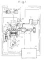
- FIG. 1 shows an internal combustion engine provided with an exhaust gas purifying apparatus and a variable valve timing mechanism according to an embodiment of the present invention.
- An air cleaner 2 filters air that is used for combustion in each cylinder 20 of the engine. The air is passed through a throttle body 4 and a surge tank (intake manifold) 6, which distributes the air to an intake duct 7 of each cylinder 20.
- the throttle body 4 has a throttle valve 5 to adjust the quantity of intake air.
- An air flow meter 40 measures the mass flow rate of intake air.
- a vacuum sensor 41 detects a pressure in the intake duct 7.
- a fuel tank 10 stores fuel.
- the fuel is pumped up by a fuel pump 11, is passed through a fuel pipe 12, and is injected by a fuel injection valve 60 into the intake duct 7.
- the intake duct 7 mixes the fuel with intake air, and the mixture is drawn into a combustion chamber of the cylinder 20 through an intake valve 24.
- the mixture in the combustion chamber 21 is compressed by a piston 23 and is ignited to explode and burn to produce torque.
- an igniter 62 controls, in response to an ignition signal, a primary current flowing to an ignition coil 63.
- the ignition coil 63 provides a secondary current to an ignition distributor 64, which fires a spark plug 65.
- the ignition distributor 64 has a reference crank angle sensor 50 and a crank angle sensor 51.
- the reference crank angle sensor 50 generates a reference position pulse at intervals of, for example, 720 degrees in crank angle.
- the crank angle sensor 51 generates a position pulse at intervals of, for example, 30 degrees in crank angle.
- An actual vehicle speed is detected by a vehicle speed sensor (not shown) that generates pulses representing the vehicle speed.
- the cylinder 20 has a cooling water path 22 for passing cooling water to cool the cylinder 20. The temperature of the cooling water is detected by a water temperature sensor 44.
- the burned air-fuel mixture produces exhaust gas, which is passed through an exhaust valve 26 into an exhaust manifold 30 and an exhaust duct 34.
- the exhaust duct 34 has an O 2 sensor 45 for detecting an oxygen concentration in the exhaust gas.
- a catalytic converter 38 is arranged in the exhaust system downstream from the O 2 sensor 45.
- the catalytic converter 38 consists of an NOx occlusion-reduction catalyst that is made of three-way catalytic components and NOx occlusion agent.
- the three-way catalytic components simultaneously promote, in the exhaust gas, the oxidization of unburned components (HC, CO) and the reduction of nitrogen oxides (NOx).
- the catalyst occludes NOx emitted from the engine while the engine is running at a lean air-fuel ratio and discharges and reduces the occluded NOx when the engine is momentarily run at a rich air-fuel ratio, to thereby maintain the NOx occluding capacity of the catalyst.
- the catalytic converter 38 purifies exhaust gas and discharges the purified gas into atmosphere.
- the piston 23 is connected to a crankshaft 81 through a connecting rod 80.
- An end of the crankshaft 81 has a timing pulley 84.
- the intake valve 24 is driven by a cam 87 attached to a cam shaft 85.
- the exhaust valve 26 is driven by a cam 88 attached to a cam shaft 86.
- An end of the cam shaft 85 has a timing pulley 89, and an end of the cam shaft 86 has a timing pulley 90.
- the timing pulleys 89 and 90 are connected to the timing pulley 84 through a timing belt 91.
- the crankshaft 81 drives the cam shafts 85 and 86, which open and close the intake valve 24 and exhaust valve 26 at given crank angles.
- the crank shaft 81 has an embedded magnetic element 82, which cooperates with a first magnetic sensor 54 arranged in the vicinity of the crank shaft 81 to generate reference pulses.
- the cam shaft 85 has an embedded magnetic element 93, which cooperates with a second magnetic sensor 55 arranged in the vicinity of the cam shaft 85 to generate reference pulses.
- the variable valve timing mechanism 92 is a known one and is arranged between the cam shaft 85 and the timing pulley 89, to rotate them relative to each other.
- the mechanism 92 has an intermediate gear having helical teeth between the cam shaft 85 and the timing pulley 89 each having external teeth.
- the intermediate gear is axially movable and connects the cam shaft 85 and timing pulley 89 to each other, to rotate them relative to each other.
- the axial movement of the intermediate gear is realized by controlling hydraulic pressure with a hydraulic pressure control valve 68.
- FIG. 2 shows the structure of an electronic engine control unit (ECU) 70 according to the embodiment of the present invention.
- the ECU 70 is a microcomputer system to carry out fuel injection control, ignition timing control, and valve timing control according to the present invention.
- a read-only memory (ROM) 73 stores programs and maps used by a central processing unit (CPU) 71.
- the CPU 71 receives signals from sensors and switches through an A/D converter 75 and an input interface 76, processes the signals, and provides control signals through drive controllers 77a to 77c.
- a random access memory (RAM) 74 temporarily stores data during the operation of the CPU 71.
- a backup RAM 79 directly receives power from a battery (not shown), to store data such as learned values even if an ignition switch is OFF.
- These elements of the ECU 70 are connected to one another through a system bus 72 composed of an address bus, a data bus, and a control bus.
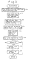
- FIG. 3 is a flowchart showing a routine of calculating a fuel injection period and ignition timing according to the fuel injection control of the present invention.
- This routine is executed at 1 ms intervals in a main routine.
- Step 301 detects engine operating conditions. Namely, step 301 reads an engine revolution speed NE based on the output of the crank angle sensor 51 and an intake duct pressure PM, i.e., a load detected by the vacuum sensor 41.
- Step 302 refers to a two-dimensional map (not shown) stored in the ROM 73 according to the values NE and PM and calculates a basic fuel injection period TP corresponding to the engine operating conditions.
- Step 303 refers to a two-dimensional map (not shown) according to the values NE and PM and calculates a lean air-fuel ratio correction coefficient FLEAN corresponding to the engine operating conditions. If the engine is running at a low or medium speed under light load, the coefficient FLEAN is set to be in the range of, for example, 0.6 to 0.8 to realize a lean air-fuel ratio. If the engine is running at a high speed under medium or heavy load, the coefficient FLEAN is set to 1.0 to achieve a rich air-fuel ratio, e.g., a stoichiometric air-fuel ratio.
- Step 305 refers to a map (not shown) stored in the ROM 73 according to the revolution speed and load as well as an air-fuel ratio detected by the O 2 sensor 45 and calculates ignition timing ⁇ .
- the ignition timing 6 is advanced as the air-fuel ratio becomes leaner from a stoichiometric air-fuel ratio of 14.5. This is because combustion in the engine becomes slower as the air-fuel ratio becomes leaner.
- Step 306 reads a water temperature THW from the water temperature sensor 44.
- Step 307 compares the water temperature THW with a reference temperature of, for example, 80 degrees and determines whether or not the engine is cold, i.e., whether or not the engine is warming up. If THW ⁇ 80, the engine is warming up, and step 308 is carried out. If THW ⁇ 80, the warming-up is complete, and the routine ends.
- Step 308 refers to a map (not shown) stored in the ROM 73 according to the water temperature THW and calculates a warm-up correction coefficient FWL.
- the fuel injection period TAU calculated in step 304 is multiplied by the coefficient FWL, to provide a corrected TAU (TAU ⁇ TAU ⁇ FWL).
- Step 309 refers to a map (not shown) stored in the ROM 73 according to the water temperature THW and calculates an ignition timing correction angle, which is set to advance the ignition timing as the water temperature becomes lower. This correction angle is added to the ignition timing ⁇ calculated in step 305, to provide a corrected ignition timing ⁇ .
- step 307 determines that the engine is warming up
- the fuel injection control of this embodiment activates the drive controller 77a to open the fuel injection valve 60 for the fuel injection period TAU calculated in step 308 at the fuel injection timing of each cylinder calculated according to the outputs of the reference crank angle sensor 50 and crank angle sensor 51.
- the ignition timing control of this embodiment detects the ignition timing ⁇ calculated in step 309 on the output of the crank angle sensor 51, and at this timing, activates the drive controller 77b to send an ignition signal to the igniter 62. Then, a primary current flows through the ignition coil 63, which provides a secondary current to the spark plug 65 to ignite a mixture of fuel and air in the combustion chamber.
- the embodiment interpolates the output of the crank angle sensor 51, which is provided at intervals of 30 degrees in crank angle, so that the ignition timing may be set at an accuracy of one degree in crank angle.
- FIG. 4 is a flowchart showing a routine of carrying out the rich spike control. This routine is carried out at 4 ms intervals.
- Step 401 determines whether or not a lean condition is met, i.e., whether or not the engine must be operated at a lean air-fuel ratio. If the lean condition is met, step 402 is carried out, and if not, step 403 is carried out. The determination of step 401 is made based on the coefficient FLEAN because, as explained in step 303 of Fig.
- the coefficient FLEAN is set to 0.6 to 0.8 if the engine is running at a light or medium speed under light load, and to 1.0 to achieve a stoichiometric air-fuel ratio if the engine is running at a high speed under medium or heavy load.
- Step 402 compares a lean time counter CLN with a reference time a, which is, for example, 30 seconds. If CLN > a, 30 seconds have passed and step 404 is carried out. If CLN ⁇ a, step 405 is carried out.
- the reference time a is determined depending on the NOx occluding capacity of the catalyst contained in the catalytic converter 38. Since the lean time counter CLN is incremented by one at 4-msec intervals, the reference time a is set to 7500 corresponding to 30 seconds.
- Step 404 sets a rich spike execution flag RSFLG to 1 to indicate that the rich spike control must be carried out.
- Step 406 carries out the rich spike control to make the air-fuel ratio of the engine rich.
- step 406 sets the coefficient FLEAN to 1.45 (14.5 / 10) to realize a target rich air-fuel ratio of, for example, 10.
- the air-fuel ratio is made rich, an oxygen concentration in the exhaust gas decreases to discharge and reduce NOx occluded in the catalyst.
- Step 407 adds 1 to a rich spike time counter CRS.
- Step 408 resets the lean time counter CLN to 0. Namely, the lean time counter CLN is reset at 4-msec intervals while the rich spike control is being executed. If step 401 determines that the lean condition is not met, step 403 resets the rich spike time counter CRS to 0.
- a reference time b which is, for example, 0.3 seconds.
- the reference time b is set so that the catalyst (the catalytic converter 38) may discharge and reduce occluded NOx and restore the NOx occluding capacity thereof. Since the rich spike counter CRS is incremented by one at 4-msec intervals, the reference time b is set to 75 corresponding to 0.3 seconds.
- Step 410 resets the rich spike execution flag RSFLG.
- Step 411 resets the rich spike time counter CRS to 0.
- Step 412 adds 1 to the lean time counter CLN.
- the rich spike control of this embodiment drives the engine at a lean air-fuel ratio for 30 seconds set by the lean time counter CLN. During this period, the catalyst occludes NOx. Thereafter, the embodiment drives the engine at a rich air-fuel ratio of, for example, 10 for 0.3 seconds set by the rich spike time counter CRS. During this period, the catalyst discharges and reduces the occluded NOx. The embodiment repeats these processes.
- variable valve timing control of the present invention will be explained. First, variable valve timing will be explained.
- Figure 5 shows the open and close timing of the intake and exhaust valves 24 and 26 and corresponding crank angles.
- the exhaust valve 26 is opened at fixed open timing EVO, which is 50 degrees before an exhaust bottom dead center according to the embodiment, and is closed at fixed close timing EVC, which is 3 degrees after an exhaust top dead center according to the embodiment.
- the intake valve 24 has a fixed valve open period and variable open timing IVO and close timing IVC.
- the most retarded open timing IVOr and close timing IVCr of the intake valve 24 serve as reference positions. Starting from these reference positions, the open and close timing IVO and IVC of the intake valve 24 are optionally advanced subject to the maximum of a valve timing displacement VTD being 60 degrees.
- the displacement VTD from the reference positions serves as a control target.
- the reference close timing IVOr is three degrees after the exhaust top dead center, and the reference close timing IVCr is 65 degrees after an intake bottom dead center. If the valve timing displacement VTD is 30 degrees in crank angle, the intake valve open timing IVO is 27 degrees before the exhaust top dead center, and the intake valve close timing is 35 degrees after the intake bottom dead center. In this embodiment, the reference open timing IVOr of the intake valve 24 is equal to the fixed close timing EVC of the exhaust valve 26 and is three degrees after the exhaust top dead center. Accordingly, the displacement VTD agrees with a valve overlap period.
- the variable valve timing control basically sets target open and close timing for the intake valve 24 according to engine operating conditions and an air-fuel ratio detected in exhaust gas and controls the variable valve timing mechanism 92 accordingly. More precisely, the variable valve timing control makes the cam shaft 85 of the intake valve 24 achieve a required rotational phase with respect to the crankshaft 81 by feedback-controlling the hydraulic pressure control valve 68 in response to signals from the first and second magnetic sensors 54 and 55. If the open and close timing of the intake valve 24 is changed in response to an air-fuel ratio detected in exhaust gas whenever the rich spike control of Fig. 4 is carried out, the cleanness of the exhaust gas and the driveability of the engine will deteriorate.
- the rich spike control is executed only for a short time, for example, 0.3 seconds, which is too short for the mechanism 92 to follow and because the rich spike control is frequently executed at intervals of 30 seconds.
- the open and close timing of the intake valve 24 is changed 600,000 times to cause a problem in the durability of the mechanism 92.
- the present invention prohibits any change in the open and close timing of the intake valve 24 if the rich spike control is being carried out.
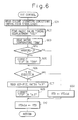
- FIG. 6 is a flowchart showing a routine of carrying out the variable valve timing control according to the present invention. This routine is carried out at 4 ms intervals.
- Step 601 detects engine operating conditions by reading an engine revolution speed NE based on the output of the crank angle sensor 51 as well as an intake air quantity GA from the air flow meter 40. The value GA is divided by the value NE, to provide a load GN.
- Step 602 refers to a two-dimensional map of Fig. 7 stored in the ROM 73 according to the revolution speed NE and load GN and calculates a target valve timing displacement VTD.
- Step 603 reads a water temperature THW from the water temperature sensor 44.
- Step 604 compares the water temperature THW with a reference temperature of, for example, 80 degrees and determines whether or not the engine is cold, i.e., whether or not the engine is warming up. If THW ⁇ 80, the engine is cold, and step 605 is carried out. If THW ⁇ 80, the warming-up is complete, and step 606 is carried out.
- Step 605 refers to a water temperature map of Fig. 8 stored in the ROM 73 and calculates a water temperature correction value OTHW, which is used to correct the target displacement VTD.
- the variable valve timing control is stopped if the water temperature THW is low. More precisely, the correction value OTHW corresponding to the water temperature THW is used to decrease the target displacement VTD obtained from the map of Fig. 7 as follows: VTD ⁇ VTD - OTHW According to the corrected displacement VTD, the variable valve timing control is carried out.
- the relationship between the water temperature THW and the variable valve timing control (VVT) is as follows:
- Step 609 corrects the target displacement VTD according to the air-fuel ratio read in step 607. This correction reduces the valve overlap period if the air-fuel ratio is lean, to stably burn a mixture of fuel and air without a misfire, and increases the valve overlap period if the air-fuel ratio is rich, e.g., is stoichiometric, to reduce fuel consumption and NOx.
- Step 610 sets the present VTD to a preceding VTDold. In this way, the variable valve timing mechanism 92 of the present invention carries out feedback control according to the corrected valve timing displacement VTD.
- the present invention occludes NOx in an NOx occlusion and reduction three-way catalyst provided for an engine if the air-fuel ratio of the engine is lean.
- the present invention lowers an oxygen concentration in the exhaust gas by regularly carrying out rich spike control for a short time without changing valve timing, i.e., a valve overlap period. Then, a variable valve timing mechanism has no problem of being forced to follow the rich spike operation.
- the present invention thus maintains the cleanness of exhaust gas and the driveability of the engine and improves the durability of the variable valve timing mechanism.
- An apparatus for, and a method of, purifying exhaust gas emitted from an internal combustion engine reduces fuel consumption under a lean operating condition and generates high torque under a rich operating condition without deteriorating the cleanness of exhaust gas and the driveability of the engine.
- the apparatus and method improve the durability of a variable valve timing mechanism of the engine.
- the engine operation involves lean and rich operating conditions.
- the variable valve timing mechanism (92) of the apparatus changes the open and close timing of at least one of intake valve (24) and exhaust valve (26) of the engine.
- the apparatus further has a catalytic converter (38) in an exhaust system, to occlude NOx under the lean operating condition and discharge and reduce the occluded NOx under the rich operating condition.
- the apparatus also has a prohibition unit (70) for prohibiting the variable valve timing mechanism (92) from changing the valve open and close timing of the valves when the air-fuel ratio of the engine is changed from lean to rich to discharge and reduce the occluded NOx.
Claims (2)
- Gerät zum Reinigen von Abgas, das von einem Verbrennungsmotor abgegeben wird, der einen mageren Betriebszustand und einen fetten Betriebszustand, der einen Betriebszustand mit einem stoichiometrischen Luft-Kraftstoff-Verhältnis umfasst, hat, mitdadurch gekennzeichnet, dasseiner Erfassungseinrichtung zum Erfassen eines Luft-Kraftstoff-Verhältnisses des Motors im Abgas undeiner katalytischen Einrichtung (38), die in dem Abgassystem des Motors angeordnet ist, um NOx im mageren Betriebszustand zu absorbieren und das absorbierte NOx im fetten Betriebszustand heraus zu lassen und zu reduzieren,
das Gerät folgendes aufweist:eine Ventilzeitabstimmungseinrichtung für ein Ändern der Öffnungs- und Schließzeit von zumindest entweder dem Einlassventil (24) oder dem Auslassventil (26) des Motors in Übereinstimmung mit dem erfassten Luft-Kraftstoff-Verhältnis,eine Fettspitzenregeleinrichtung (70) zum Ausführen einer Fettspitzenregelung für ein Verändern des Luft-Kraftstoff-Verhältnisses des Motors von mager nach fett, um dadurch das absorbierte NOx heraus zu lassen und zu reduzieren, undeine Verhinderungseinrichtung (70), die verhindert, dass die Ventilzeitabstimmungseinrichtung (92) die Öffnungszeit und Schließzeit der Ventile ändert, wenn die Fettspitzenregelungeinrichtung die Fettspitzenregelung ausführt. - Verfahren zum Reinigen von Abgas, das von einem Verbrennungsmotor abgegeben wird, der einen mageren Betriebszustand und einen fetten Betriebszustand, der einen Betriebszustand mit einem stoichiometrischen Luft-Kraftstoff-Verhältnis umfasst, hat, und ein Luft-Kraftstoff-Verhältnis des Motors erfasst,
gekennzeichnet, durch
die folgenden Schritte:Ändern der Öffnungs- und Schließzeit von zumindest entweder dem Einlassventil oder dem Auslassventil des Motors in Übereinstimmung mit dem erfassten Luft-Kraftstoff-Verhältnis des Motors,Ausführen einer Fettspitzenregelung, um vorübergehend das Luft-Kraftstoff-Verhältnis des Motors fett zu gestalten, um die Sauerstoffkonzentration in dem Abgas zu reduzieren, so dass eine in einem Abgassystem des Motors angeordnete katalytische Einrichtung NOx herauslassen und reduzieren kann, bevor durch die katalytische Einrichtung im mageren Betriebszustand absorbierte NOx die Absorptionskapazität für NOx der katalytischen Einrichtung erreicht; undVerhindern jeglicher Änderung der Öffnungs- und Schließzeit der Ventile während des Ausführens der Fettspitzenregelung.
Applications Claiming Priority (3)
| Application Number | Priority Date | Filing Date | Title |
|---|---|---|---|
| JP23794696A JP2871615B2 (ja) | 1996-09-09 | 1996-09-09 | 内燃機関の排気浄化装置 |
| JP237946/96 | 1996-09-09 | ||
| JP23794696 | 1996-09-09 |
Publications (3)
| Publication Number | Publication Date |
|---|---|
| EP0828068A2 EP0828068A2 (de) | 1998-03-11 |
| EP0828068A3 EP0828068A3 (de) | 1999-09-01 |
| EP0828068B1 true EP0828068B1 (de) | 2001-01-17 |
Family
ID=17022813
Family Applications (1)
| Application Number | Title | Priority Date | Filing Date |
|---|---|---|---|
| EP97115538A Expired - Lifetime EP0828068B1 (de) | 1996-09-09 | 1997-09-08 | Verfahren und Vorrichtung zum Reinigen von Abgasen einer Brennkraftmaschine |
Country Status (5)
| Country | Link |
|---|---|
| US (1) | US5848529A (de) |
| EP (1) | EP0828068B1 (de) |
| JP (1) | JP2871615B2 (de) |
| KR (1) | KR100269842B1 (de) |
| DE (1) | DE69703918T2 (de) |
Families Citing this family (40)
| Publication number | Priority date | Publication date | Assignee | Title |
|---|---|---|---|---|
| US8215292B2 (en) | 1996-07-17 | 2012-07-10 | Bryant Clyde C | Internal combustion engine and working cycle |
| DE19712356C1 (de) * | 1997-03-25 | 1998-07-09 | Daimler Benz Ag | Verfahren zum Vermindern von schädlichen Abgasemissionen eines mit magerem Kraftstoff/Luftgemisch betriebenen Otto-Motores |
| JP3123474B2 (ja) * | 1997-07-28 | 2001-01-09 | トヨタ自動車株式会社 | 内燃機関の排気浄化装置 |
| JP3286572B2 (ja) * | 1997-08-25 | 2002-05-27 | 本田技研工業株式会社 | ハイブリッド車両におけるトルクショック軽減装置 |
| US6148612A (en) * | 1997-10-13 | 2000-11-21 | Denso Corporation | Engine exhaust gas control system having NOx catalyst |
| US6021638A (en) * | 1997-11-24 | 2000-02-08 | Engelhard Corporation | Engine management strategy to improve the ability of a catalyst to withstand severe operating enviroments |
| JP3569120B2 (ja) * | 1997-12-25 | 2004-09-22 | トヨタ自動車株式会社 | 希薄燃焼内燃機関の燃焼制御装置 |
| JP3521790B2 (ja) * | 1998-03-25 | 2004-04-19 | 株式会社デンソー | 内燃機関の制御装置 |
| DE19823021B4 (de) * | 1998-05-22 | 2004-08-12 | Fev Motorentechnik Gmbh | Verfahren zum Betrieb einer fremdgezündeten Kolbenbrennkraftmaschine mit geregeltem Abgaskatalysator und elektromagnetisch betätigten Gaswechselventilen |
| JP2000073800A (ja) | 1998-08-28 | 2000-03-07 | Hitachi Ltd | 電磁駆動式吸排気バルブを備えたエンジンの制御装置 |
| JP4108223B2 (ja) | 1999-05-12 | 2008-06-25 | 本田技研工業株式会社 | 内燃機関の制御装置 |
| JP3854013B2 (ja) * | 1999-06-10 | 2006-12-06 | 三菱電機株式会社 | 内燃機関の排出ガス浄化装置 |
| SE521677C2 (sv) * | 1999-06-11 | 2003-11-25 | Volvo Personvagnar Ab | Metod för att minska ämnen i avgaser från en förbränningsmotor |
| SE521981C2 (sv) * | 1999-06-11 | 2003-12-23 | Volvo Personvagnar Ab | Metod för att minska ämnen i avgaser från en förbränningsmotor |
| US6560527B1 (en) * | 1999-10-18 | 2003-05-06 | Ford Global Technologies, Inc. | Speed control method |
| US6470869B1 (en) | 1999-10-18 | 2002-10-29 | Ford Global Technologies, Inc. | Direct injection variable valve timing engine control system and method |
| US6978764B1 (en) | 1999-10-18 | 2005-12-27 | Ford Global Technologies, Inc. | Control method for a vehicle having an engine |
| US6712041B1 (en) * | 1999-10-18 | 2004-03-30 | Ford Global Technologies, Inc. | Engine method |
| US7398762B2 (en) * | 2001-12-18 | 2008-07-15 | Ford Global Technologies, Llc | Vehicle control system |
| JP3496593B2 (ja) * | 1999-09-30 | 2004-02-16 | マツダ株式会社 | 火花点火式直噴エンジンの制御装置 |
| US7299786B2 (en) | 2004-02-05 | 2007-11-27 | Ford Global Technologies Llc | Vehicle control system |
| SE523401C2 (sv) | 2000-04-27 | 2004-04-13 | Volvo Personvagnar Ab | Metod för att minska ämnen i avgaser från en förbränningsmotor |
| DE10156140B4 (de) * | 2000-11-21 | 2005-12-15 | Mitsubishi Jidosha Kogyo K.K. | Variable Ventilsteuerung |
| JP3933386B2 (ja) * | 2000-11-29 | 2007-06-20 | 株式会社日立製作所 | 内燃機関の可変バルブタイミング制御装置 |
| DE10135303A1 (de) * | 2001-07-19 | 2003-02-13 | Bosch Gmbh Robert | Verfahren und Vorrichtung zur Abgasnachbehandlung in Verbrennungskraftmaschinen |
| US6722121B2 (en) * | 2002-07-22 | 2004-04-20 | International Engine Intellectual Property Company, Llc | Control strategy for regenerating a NOx adsorber catalyst in an exhaust system of an engine having a variable valve actuation mechanism |
| AU2003262001B2 (en) * | 2002-09-10 | 2007-10-11 | Toyota Jidosha Kabushiki Kaisha | Exhaust gas clarifying device for internal combustion engine |
| JP3867672B2 (ja) * | 2003-01-27 | 2007-01-10 | トヨタ自動車株式会社 | 筒内噴射式内燃機関の燃焼制御装置 |
| US7043901B2 (en) * | 2003-03-20 | 2006-05-16 | Ford Global Technologies, Llc | Device and method for internal combustion engine control |
| US7603847B2 (en) * | 2003-03-21 | 2009-10-20 | Ford Global Technologies, Llc | Device and method for internal combustion engine control |
| US7287371B2 (en) * | 2003-03-21 | 2007-10-30 | Ford Global Technologies Llc | Device and method for internal combustion engine control |
| US7063056B2 (en) * | 2004-05-25 | 2006-06-20 | Mitsubishi Jidosha Kogyo Kabushiki Kaisha | Valve timing control apparatus for engine |
| JP4692118B2 (ja) | 2005-07-15 | 2011-06-01 | トヨタ自動車株式会社 | エンジンの制御装置 |
| JP4780059B2 (ja) | 2007-08-09 | 2011-09-28 | トヨタ自動車株式会社 | 内燃機関の制御装置 |
| DE102008036127A1 (de) * | 2008-08-01 | 2010-02-04 | Emitec Gesellschaft Für Emissionstechnologie Mbh | Verfahren zum Betrieb einer Abgasanlage mit Lambda-Regelung |
| US10316788B2 (en) | 2013-02-27 | 2019-06-11 | Ford Global Technologies, Llc | Reducing engine misfire due to charge air cooler condensate using in-cylinder enrichment and a positive valve overlap |
| JP5967064B2 (ja) * | 2013-12-13 | 2016-08-10 | トヨタ自動車株式会社 | 内燃機関の制御装置 |
| JP6252450B2 (ja) * | 2014-11-28 | 2017-12-27 | トヨタ自動車株式会社 | 内燃機関の制御装置 |
| GB2545876A (en) * | 2015-08-13 | 2017-07-05 | Gm Global Tech Operations Llc | A method of operating an internal combustion engine |
| US11015540B2 (en) | 2016-10-07 | 2021-05-25 | Cummins Inc. | Systems and methods for in-cylinder fuel dosing for exhaust aftertreatment system thermal management |
Family Cites Families (15)
| Publication number | Priority date | Publication date | Assignee | Title |
|---|---|---|---|---|
| JPS5977025A (ja) * | 1982-10-25 | 1984-05-02 | Mazda Motor Corp | デイ−ゼルエンジンの排気ガス浄化装置 |
| JPH03164537A (ja) * | 1989-11-21 | 1991-07-16 | Mitsubishi Electric Corp | 内燃機関のバルブタイミング制御装置 |
| JP2924249B2 (ja) * | 1991-03-08 | 1999-07-26 | トヨタ自動車株式会社 | 内燃機関の排気浄化装置 |
| JP3219153B2 (ja) * | 1991-07-31 | 2001-10-15 | マツダ株式会社 | バルブタイミング制御装置 |
| WO1993007363A1 (fr) | 1991-10-03 | 1993-04-15 | Toyota Jidosha Kabushiki Kaisha | Dispositif pour purifier les gaz d'echappement d'un moteur a combustion interne |
| WO1993025805A1 (en) * | 1992-06-12 | 1993-12-23 | Toyota Jidosha Kabushiki Kaisha | Exhaust emission control system for internal combustion engine |
| WO1993025806A1 (en) * | 1992-06-12 | 1993-12-23 | Toyota Jidosha Kabushiki Kaisha | Exhaust emission control system for internal combustion engine |
| US5433074A (en) * | 1992-07-30 | 1995-07-18 | Toyota Jidosha Kabushiki Kaisha | Exhaust gas purification device for an engine |
| US5386694A (en) * | 1992-08-24 | 1995-02-07 | Honda Giken Kogyo Kabushiki Kaisha | Control system for internal combustion engines |
| JP2605579B2 (ja) * | 1993-05-31 | 1997-04-30 | トヨタ自動車株式会社 | 内燃機関の排気浄化装置 |
| US5427071A (en) * | 1994-05-04 | 1995-06-27 | Chrysler Corporation | Method of catalyst purging fuel lean-out for internal combustion engines |
| JPH0886238A (ja) * | 1994-09-16 | 1996-04-02 | Honda Motor Co Ltd | 内燃機関の空燃比制御装置 |
| US5483195A (en) * | 1994-10-20 | 1996-01-09 | Northern Telecom Limited | Second generation low noise microwave voltage controlled oscillator |
| JP3440654B2 (ja) * | 1994-11-25 | 2003-08-25 | トヨタ自動車株式会社 | 排気浄化装置 |
| JP3079933B2 (ja) * | 1995-02-14 | 2000-08-21 | トヨタ自動車株式会社 | 内燃機関の排気浄化装置 |
-
1996
- 1996-09-09 JP JP23794696A patent/JP2871615B2/ja not_active Expired - Lifetime
-
1997
- 1997-07-28 KR KR1019970037122A patent/KR100269842B1/ko not_active IP Right Cessation
- 1997-09-08 EP EP97115538A patent/EP0828068B1/de not_active Expired - Lifetime
- 1997-09-08 DE DE69703918T patent/DE69703918T2/de not_active Expired - Lifetime
- 1997-09-08 US US08/933,618 patent/US5848529A/en not_active Expired - Lifetime
Also Published As
| Publication number | Publication date |
|---|---|
| EP0828068A3 (de) | 1999-09-01 |
| KR19980024127A (ko) | 1998-07-06 |
| JP2871615B2 (ja) | 1999-03-17 |
| US5848529A (en) | 1998-12-15 |
| EP0828068A2 (de) | 1998-03-11 |
| KR100269842B1 (ko) | 2000-10-16 |
| DE69703918T2 (de) | 2001-06-07 |
| DE69703918D1 (de) | 2001-02-22 |
| JPH1082333A (ja) | 1998-03-31 |
Similar Documents
| Publication | Publication Date | Title |
|---|---|---|
| EP0828068B1 (de) | Verfahren und Vorrichtung zum Reinigen von Abgasen einer Brennkraftmaschine | |
| JP3123398B2 (ja) | 内燃機関の連続可変バルブタイミング制御装置 | |
| JP3011070B2 (ja) | バルブタイミング連続可変機構付き内燃機関における吸入空気量検出装置 | |
| EP0972925B1 (de) | Brennkraftmaschine | |
| US5881552A (en) | Control system for internal combustion engines and control system for vehicles | |
| US20090070014A1 (en) | Control system for internal combustion engine | |
| US20020112467A1 (en) | Apparatus for detecting fault in exhaust system of internal combustion engine | |
| WO2005075803A1 (ja) | エンジンの制御装置 | |
| JPH08312398A (ja) | 内燃エンジンのアイドル回転数制御装置 | |
| US5501073A (en) | Ignition timing control system for internal combustion engines | |
| JP3085181B2 (ja) | 内燃機関の点火時期制御装置 | |
| US5640939A (en) | Engine control apparatus | |
| US5622049A (en) | Control system with function of protecting catalytic converter for internal combustion engines for automotive vehicles | |
| EP0866219B1 (de) | Sperrsteuerungssystem für die Kraftstoffeinspritzung in einer Brennkraftmaschine | |
| JP2001050040A (ja) | 内燃機関の排気浄化装置 | |
| JPH08189388A (ja) | 内燃エンジンの排気浄化触媒装置及び排気浄化触媒の温度検出装置 | |
| US5600949A (en) | Exhaust gas-purifying system for internal combustion engines | |
| JPH09126004A (ja) | 内燃機関の制御装置 | |
| JPH0972225A (ja) | 連続可変式バルブタイミング制御装置 | |
| US6505604B2 (en) | Ignition timing control apparatus for internal combustion engine | |
| JPH0979057A (ja) | 内燃機関の制御装置 | |
| JPH0612227Y2 (ja) | 内燃機関のバルブリフト特性切換え制御装置 | |
| JPH06185350A (ja) | 内燃機関の排気浄化装置における暖機制御方法 | |
| JP2001065391A (ja) | 内燃機関の空燃比制御装置 | |
| JPH0754697A (ja) | エンジンの制御装置 |
Legal Events
| Date | Code | Title | Description |
|---|---|---|---|
| PUAI | Public reference made under article 153(3) epc to a published international application that has entered the european phase |
Free format text: ORIGINAL CODE: 0009012 |
|
| 17P | Request for examination filed |
Effective date: 19970908 |
|
| AK | Designated contracting states |
Kind code of ref document: A2 Designated state(s): DE FR GB |
|
| AX | Request for extension of the european patent |
Free format text: AL;LT;LV;RO;SI |
|
| PUAL | Search report despatched |
Free format text: ORIGINAL CODE: 0009013 |
|
| AK | Designated contracting states |
Kind code of ref document: A3 Designated state(s): AT BE CH DE DK ES FI FR GB GR IE IT LI LU MC NL PT SE |
|
| AX | Request for extension of the european patent |
Free format text: AL;LT;LV;RO;SI |
|
| RIC1 | Information provided on ipc code assigned before grant |
Free format text: 6F 02D 41/14 A, 6F 02D 33/02 B, 6F 02D 13/02 B, 6F 02D 41/02 B |
|
| GRAG | Despatch of communication of intention to grant |
Free format text: ORIGINAL CODE: EPIDOS AGRA |
|
| AKX | Designation fees paid |
Free format text: DE FR GB |
|
| 17Q | First examination report despatched |
Effective date: 20000405 |
|
| GRAG | Despatch of communication of intention to grant |
Free format text: ORIGINAL CODE: EPIDOS AGRA |
|
| GRAH | Despatch of communication of intention to grant a patent |
Free format text: ORIGINAL CODE: EPIDOS IGRA |
|
| GRAH | Despatch of communication of intention to grant a patent |
Free format text: ORIGINAL CODE: EPIDOS IGRA |
|
| GRAA | (expected) grant |
Free format text: ORIGINAL CODE: 0009210 |
|
| AK | Designated contracting states |
Kind code of ref document: B1 Designated state(s): DE FR GB |
|
| ET | Fr: translation filed | ||
| REF | Corresponds to: |
Ref document number: 69703918 Country of ref document: DE Date of ref document: 20010222 |
|
| PLBE | No opposition filed within time limit |
Free format text: ORIGINAL CODE: 0009261 |
|
| STAA | Information on the status of an ep patent application or granted ep patent |
Free format text: STATUS: NO OPPOSITION FILED WITHIN TIME LIMIT |
|
| REG | Reference to a national code |
Ref country code: GB Ref legal event code: IF02 |
|
| 26N | No opposition filed | ||
| REG | Reference to a national code |
Ref country code: GB Ref legal event code: 746 Effective date: 20130624 |
|
| REG | Reference to a national code |
Ref country code: DE Ref legal event code: R084 Ref document number: 69703918 Country of ref document: DE Effective date: 20130614 |
|
| REG | Reference to a national code |
Ref country code: FR Ref legal event code: PLFP Year of fee payment: 20 |
|
| PGFP | Annual fee paid to national office [announced via postgrant information from national office to epo] |
Ref country code: GB Payment date: 20160907 Year of fee payment: 20 Ref country code: DE Payment date: 20160831 Year of fee payment: 20 |
|
| PGFP | Annual fee paid to national office [announced via postgrant information from national office to epo] |
Ref country code: FR Payment date: 20160816 Year of fee payment: 20 |
|
| REG | Reference to a national code |
Ref country code: DE Ref legal event code: R071 Ref document number: 69703918 Country of ref document: DE |
|
| REG | Reference to a national code |
Ref country code: GB Ref legal event code: PE20 Expiry date: 20170907 |
|
| PG25 | Lapsed in a contracting state [announced via postgrant information from national office to epo] |
Ref country code: GB Free format text: LAPSE BECAUSE OF EXPIRATION OF PROTECTION Effective date: 20170907 |