EP0826796B1 - Method and equipment for growing single crystals - Google Patents
Method and equipment for growing single crystals Download PDFInfo
- Publication number
- EP0826796B1 EP0826796B1 EP96910223A EP96910223A EP0826796B1 EP 0826796 B1 EP0826796 B1 EP 0826796B1 EP 96910223 A EP96910223 A EP 96910223A EP 96910223 A EP96910223 A EP 96910223A EP 0826796 B1 EP0826796 B1 EP 0826796B1
- Authority
- EP
- European Patent Office
- Prior art keywords
- single crystal
- lifting jig
- hanging member
- moving
- cone part
- Prior art date
- Legal status (The legal status is an assumption and is not a legal conclusion. Google has not performed a legal analysis and makes no representation as to the accuracy of the status listed.)
- Expired - Lifetime
Links
Images


Classifications
-
- C—CHEMISTRY; METALLURGY
- C30—CRYSTAL GROWTH
- C30B—SINGLE-CRYSTAL GROWTH; UNIDIRECTIONAL SOLIDIFICATION OF EUTECTIC MATERIAL OR UNIDIRECTIONAL DEMIXING OF EUTECTOID MATERIAL; REFINING BY ZONE-MELTING OF MATERIAL; PRODUCTION OF A HOMOGENEOUS POLYCRYSTALLINE MATERIAL WITH DEFINED STRUCTURE; SINGLE CRYSTALS OR HOMOGENEOUS POLYCRYSTALLINE MATERIAL WITH DEFINED STRUCTURE; AFTER-TREATMENT OF SINGLE CRYSTALS OR A HOMOGENEOUS POLYCRYSTALLINE MATERIAL WITH DEFINED STRUCTURE; APPARATUS THEREFOR
- C30B15/00—Single-crystal growth by pulling from a melt, e.g. Czochralski method
- C30B15/30—Mechanisms for rotating or moving either the melt or the crystal
-
- C—CHEMISTRY; METALLURGY
- C30—CRYSTAL GROWTH
- C30B—SINGLE-CRYSTAL GROWTH; UNIDIRECTIONAL SOLIDIFICATION OF EUTECTIC MATERIAL OR UNIDIRECTIONAL DEMIXING OF EUTECTOID MATERIAL; REFINING BY ZONE-MELTING OF MATERIAL; PRODUCTION OF A HOMOGENEOUS POLYCRYSTALLINE MATERIAL WITH DEFINED STRUCTURE; SINGLE CRYSTALS OR HOMOGENEOUS POLYCRYSTALLINE MATERIAL WITH DEFINED STRUCTURE; AFTER-TREATMENT OF SINGLE CRYSTALS OR A HOMOGENEOUS POLYCRYSTALLINE MATERIAL WITH DEFINED STRUCTURE; APPARATUS THEREFOR
- C30B15/00—Single-crystal growth by pulling from a melt, e.g. Czochralski method
- C30B15/20—Controlling or regulating
- C30B15/22—Stabilisation or shape controlling of the molten zone near the pulled crystal; Controlling the section of the crystal
-
- Y—GENERAL TAGGING OF NEW TECHNOLOGICAL DEVELOPMENTS; GENERAL TAGGING OF CROSS-SECTIONAL TECHNOLOGIES SPANNING OVER SEVERAL SECTIONS OF THE IPC; TECHNICAL SUBJECTS COVERED BY FORMER USPC CROSS-REFERENCE ART COLLECTIONS [XRACs] AND DIGESTS
- Y10—TECHNICAL SUBJECTS COVERED BY FORMER USPC
- Y10S—TECHNICAL SUBJECTS COVERED BY FORMER USPC CROSS-REFERENCE ART COLLECTIONS [XRACs] AND DIGESTS
- Y10S117/00—Single-crystal, oriented-crystal, and epitaxy growth processes; non-coating apparatus therefor
- Y10S117/90—Apparatus characterized by composition or treatment thereof, e.g. surface finish, surface coating
-
- Y—GENERAL TAGGING OF NEW TECHNOLOGICAL DEVELOPMENTS; GENERAL TAGGING OF CROSS-SECTIONAL TECHNOLOGIES SPANNING OVER SEVERAL SECTIONS OF THE IPC; TECHNICAL SUBJECTS COVERED BY FORMER USPC CROSS-REFERENCE ART COLLECTIONS [XRACs] AND DIGESTS
- Y10—TECHNICAL SUBJECTS COVERED BY FORMER USPC
- Y10S—TECHNICAL SUBJECTS COVERED BY FORMER USPC CROSS-REFERENCE ART COLLECTIONS [XRACs] AND DIGESTS
- Y10S117/00—Single-crystal, oriented-crystal, and epitaxy growth processes; non-coating apparatus therefor
- Y10S117/911—Seed or rod holders
-
- Y—GENERAL TAGGING OF NEW TECHNOLOGICAL DEVELOPMENTS; GENERAL TAGGING OF CROSS-SECTIONAL TECHNOLOGIES SPANNING OVER SEVERAL SECTIONS OF THE IPC; TECHNICAL SUBJECTS COVERED BY FORMER USPC CROSS-REFERENCE ART COLLECTIONS [XRACs] AND DIGESTS
- Y10—TECHNICAL SUBJECTS COVERED BY FORMER USPC
- Y10T—TECHNICAL SUBJECTS COVERED BY FORMER US CLASSIFICATION
- Y10T117/00—Single-crystal, oriented-crystal, and epitaxy growth processes; non-coating apparatus therefor
- Y10T117/10—Apparatus
- Y10T117/1024—Apparatus for crystallization from liquid or supercritical state
- Y10T117/1032—Seed pulling
Definitions
- the present invention relates to single crystal growing methods and apparatuses for manufacturing a single crystal by a Czochralski (CZ) method and more particularly, to a single crystal growing method and apparatus for pulling and suitably manufacturing a heavy-weight single crystal safely without generation of dislocation.
- CZ Czochralski
- a Czochralski (CZ) method As one of methods for pulling a single crystal from a crucible containing a melt of such semiconductor material as silicon, a Czochralski (CZ) method has been conventionally employed, which is schematically shown in Fig. 17.
- CZ Czochralski
- a seed crystal 12 is brought into contact with a melt 10a within a crucible 10 installed in a heating chamber (not shown) and then pulled, moving-up operation of the seed crystal 12 at its pulling speed causes a neck part 13 to be formed in a lower part of the seed crystal 12.
- a single crystal part 15 which is a combination of a cone-shaped part 15a and a straight body part 15b
- Reference numeral 41 denotes a hanging member for pulling the seed crystal.
- the single crystal part 15 has conventionally been as small as about 20-30kg in weight and also small in diameter. In these years, however, for the purpose of increasing efficiency and yield in semiconductor production, the single crystal part 15 has been demanded to have an larger diameter and larger weight. For this reason, such a neck part 13 as shown in Fig. 17 has had a problem that it cannot safely support the single crystal part 15 as heavy as about 100-200kg. In order to solve the problem, there have been employed a single crystal growing method and apparatus in which a corrugated portion 14 formed between the neck part 13 and single crystal part 15 is held as grasped by a pair of lifting jig 14a and pulled, as shown in, e.g., Fig. 18.
- a seed crystal is first pulled by a wire connected to the seed crystal, a narrow part (corresponding to the corrugated portion 14 in the aforementioned example) as a pulled part formed following the seed crystal is grasped by a grasping lever (corresponding to the aforementioned lifting jig 14a) located at a predetermined position, and then the single crystal is further pulled by the wire and lever.
- the neck part 13 shown in Fig. 17 generally has a diameter of about 3-4mm and has a strength insufficient to pull the heavy-weight single crystal part 15.
- Japanese Patent Application Laid-Open Publication No. 5-43379 a technique in which pulling conditions are devised so that the neck part 13 can have a diameter of 4.5mm-10mm.
- this method is insufficient to form the single crystal part 15 safely and without generation of dislocation.
- the single crystal can be held by a raised and recessed portion (verge: Journal of Crystal Growth 52(1981)391-395) in a neck part formed to cause dislocation to disappear from the single crystal or by a part of finely fluctuated diameters caused during the growth of the single crystal.
- the biggest problem is that it is difficult to engage the lifting jig 14a with the corrugated portion 14 or with the single crystal part 15 being pulled as rotated under a condition of no impact force. Even a slight impact force applied to the single crystal part 15 during the formation of the single crystal part 15 results in generation of dislocation in the crystal. Accordingly, in order to form a good quality of single crystal part 15, it is necessary to engage the lifting jig 14a under a condition of no impact force. However, no consideration is paid to this respect in the aforementioned prior arts.
- a method for growing a single crystal having a neck part continuously connected to a seed crystal, a cone part and a straight body part characterised in that said neck part, cone part and straight body part are formed by pulling a hanging member connected to said seed crystal, a lifting jig is engaged in a recess in a corrugated portion on a surface of said single crystal which is moved up to a predetermined position by raising the hanging member, a load pulled by the hanging member is shifted to the lifting jig and thereafter pulling operation of the single crystal is carried out only by the lifting jig (first aspect of the invention; "Invention 1").
- a method for growing a single crystal having a neck part under a seed crystal, a cone part, an inverted right cone part having a taper, defined by the difference between the maximum and minimum diameters of the inverted cone part divided by the length of the inverted cone part, of 0.1-0.3 and a straight body part in this order characterised in that a lifting jig is engaged with an outer peripheral surface of said inverted right cone part which is moved up to a predetermined position by raising the hanging member connected to said seed crystal, a load pulled by the hanging member is shifted to the lifting jig and thereafter pulling operation of the single crystal is carried out only by the lifting jig ("Invention 2"),
- the corrugated portion on said single crystal may be formed as a result of fine fluctuations in diameter caused by variations in temperature, pulling speed and convection during growth of said single crystal ("Invention 3").
- a corrugated portion of said neck part may be formed as a verge for the purpose of causing dislocation to disappear from the single crystal ("Invention 4").
- said neck part, said cone part and a corrugated part of said straight body part may be intentionally formed ("Invention 5").
- said inverted right cone part may be formed by controlling at least one of a pulling speed of the single crystal and a temperature of a melt within a crucible ("Invention 6").
- a pulling speed V B of said lifting jig is preferably increased gradually from zero immediately after the engagement of said lifting jig so that a speed V corresponding to an addition of said pulling speed V B of the lifting jig to a pulling speed V A of said hanging member after the engagement of said lifting jig is equal to the pulling speed V SE of said hanging member immediately before said lifting jig is engaged and, in synchronism therewith, the pulling speed V A of said hanging member is decreased gradually from the speed V SE ("Invention 7").
- a load pulled by said hanging member is measured so that, after a measured load value becomes zero, the pulling speed V A of the hanging member is set at zero ("Invention 8").
- an apparatus for growing a dislocation-free single crystal having a neck part continuously connected to a seed crystal, a cone part and a straight body part
- said apparatus comprises a hanging member and means for moving said hanging member up and down, and a lifting jig adapted to engage in a recessed portion of a corrugated portion on a surface of said single crystal and means for moving said lifting jig up and down
- said means for moving said hanging member and said means for moving said lifting jig being adapted for moving said hanging member and said lifting jig up and down independently of each other, whereby said neck part continuously connected to said seed crystal, said cone part and a part of said straight body part may be formed whilst said single crystal is hanged by said hanging member connected to said seed crystal and by said lifting jig engaged in said recessed portion of said corrugated portion on said surface of said single crystal, and whereby said dislocation-free single crystal may be formed by pulling the single crystal without applying
- an apparatus for growing a dislocation-free single crystal having a neck part under a seed crystal, a cone part, an inverted right cone part having a taper, defined by the difference between the maximum and minimum diameters of the inverted cone part divided by the length of the inverted cone part, of 0.1-0.3 and a straight body part in this order, characterised in that said apparatus comprises a hanging member and means for moving said hanging member up and down, and a lifting jig adapted to engage with an outer peripheral surface of said inverted right cone part and means for moving said lifting jig up and down, said means for moving said hanging member and said means for moving said lifting jig being adapted for moving said hanging member and said lifting jig up and down independently of each other, whereby said single crystal may be hanged by said hanging member connected to said seed crystal and by said lifting jig engaged with said outer peripheral surface of said inverted right cone part, and whereby said dislocation-free single crystal may be formed by pulling
- said means for moving said lifting jig comprises a slider disposed as opposed to a crucible containing a melt of semiconductor material and a slider moving mechanism engaged with said slider for moving and guiding the slider in a vertical direction at a speed V B ; said apparatus further includes a retaining case pivotably supported on said slider moving mechanism and a mechanism for rotating said retaining case; said means for moving said hanging member comprises a hanging member moving up/down mechanism provided in said retaining case for moving the hanging member connected to said seed crystal at a speed V A ; said apparatus further includes load measuring means for measuring a load applied to the hanging member moving up/down mechanism as the hanging member is moved and a lifting jig driving mechanism for moving said lifting jig provided in said retaining case to be releasably engaged in a recess in said corrugated portion toward said recess or away therefrom; and said controller is connected to said slider moving mechanism, retaining case rotating mechanism, hanging member moving up/down mechanism, load measuring means and lifting j
- said means for moving said lifting jig comprises a slider disposed as opposed to a crucible containing a melt of semiconductor material, a slider moving mechanism engaged with said slider for moving and guiding the slider in a vertical direction at a speed V B ; said apparatus further includes a retaining case pivotably supported on said slider moving mechanism, a mechanism for rotating said retaining case; said means for moving said hanging member comprises a hanging member moving up/down mechanism provided in said retaining case for moving the hanging member connected to said seed crystal at a speed V A ; said apparatus further includes load measuring means for measuring a load applied to the hanging member moving up/down mechanism as the hanging member is moved and a lifting jig driving mechanism for moving said lifting jig provided in said retaining case to be releasably engaged on an outer peripheral surface of said inverted right cone part toward said outer peripheral surface or away therefrom; and said controller is connected to said slider moving mechanism, retaining case rotating mechanism, hanging member moving up/down mechanism, load measuring means and lifting j
- moving-up speeds of said hanging member and lifting jig are preferably controlled by a diameter controller "Invention 13").
- said crucible is provided within a heating chamber, a crystal unloading chamber is provided above said heating chamber, and said crystal unloading chamber is formed to be expanded and contracted in its vertical direction ("Invention 14").
- said crystal unloading chamber comprises a bellows ("Invention 15").
- said lifting jig comprises a pair of arm-shaped members intermediate parts of which are pivoted to said retaining case and which are provided at their lower ends with engagements to be engaged in the recess of said corrugated portion, and said lifting jig driving mechanism comprises a pair of hydraulic cylinders or motors coupled to upper ends of said arm-shaped members ("Invention 16").
- said lifting jig comprises a pair of arm-shaped members intermediate parts of which are pivoted to said retaining case and which are provided at their lower ends with engagements to be engaged with an outer peripheral surface of said inverted right cone part, and said lifting jig driving mechanism comprises a pair of hydraulic cylinders or motors coupled to upper ends of said arm-shaped members ("Invention 17").
- detecting means for detecting positions of surfaces of said neck part, cone part and straight body part of the single crystal pulled by said hanging member are disposed at predetermined positions on an immobile side of said apparatus ("Invention 19").
- detecting means for detecting positions of surfaces of said neck part, cone part, inverted right cone part and straight body part of the single crystal pulled by said hanging member are disposed at predetermined positions on an immobile side of said apparatus ("Invention 20").
- the seed crystal is provided to the tip end of the hanging member, the seed crystal is brought into contact with the melt within the crucible, and the rotating mechanism is actuated while the hanging member is pulled upwardly by the hanging member pulling up/down mechanism.
- the neck part, cone part and straight body part both of the cone and straight body parts are connectively referred to as the single crystal part
- the lifting-jig driving mechanism is actuated so that the lifting jig is engaged in the recess in the corrugated portion on the surface of the single crystal, while the lifting jig is moved up by the slider moving mechanism simultaneously with the above engagement at the speed V B and is also rotated by the rotating mechanism.
- the speeds of the hanging member and lifting jig are controlled so that, during a constant time immediately after the lifting jig is engaged in the recess in the corrugated portion, the addition of the pulling speed V A of the hanging member and the pulling speed V B of the hanging holder becomes equal to the speed V SE .
- the transfer from the hanging member to the lifting jig can be smoothly carried out to thereby prevent generation of an impact force.
- the pulling and rotation of only the lifting jig cause the single crystal part to be stably pulled, so that the single crystal part can have a predetermined shape.
- the seed crystal is provided to the tip end of the hanging member, the seed crystal is brought into contact with the melt within the crucible, and the rotating mechanism is actuated while the hanging member is pulled by the hanging member moving up/down mechanism.
- the neck part, cone part and inverted right cone part are formed.
- the lifting-jig driving mechanism is actuated so that the lifting jig is engaged with the outer peripheral surface of the inverted right cone part, while the lifting jig is moved up by the slider moving mechanism simultaneously with the above engagement at the speed V B and is also rotated by the rotating mechanism.
- the speeds of the hanging member and lifting jig are controlled so that, during a constant time immediately after the lifting jig is engaged with the outer peripheral surface, the addition of the pulling speed V A of the hanging member and the pulling speed V B of the lifting jig becomes equal to the speed V SE .
- the transfer from the hanging member to the lifting jig can be smoothly carried out to thereby prevent generation of an impact force.
- the pulling and rotation of only the lifting jig cause the entire single crystal to be stably pulled, so that the single crystal part can have a predetermined shape.
- Fig. 1 is a general arrangement of the present embodiment
- Fig. 2 is an axial cross-sectional view of a detailed structure of a hanging members and holding apparatus therearound
- Fig. 3 is an axial cross-sectional view of a part of a schematic structure of a bellows as a flexible elastic member in the present embodiment
- Fig. 4 is an axial cross-sectional view of a part of a detection means
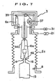
- Figs. 5 to 7 are axial cross-sectional views for explaining the operation of the present embodiment
- Fig. 8 is an axial cross-sectional view for explaining transfer of the single crystal from a hanging member to the lifting jig
- FIG. 9 is a diagram showing a relationship between elapsed time of single-crystal pulling operation by the hanging member and pulling rate
- Fig. 10 is a diagram showing changes in the rates of the hanging member and lifting jig when the single crystal is transferred from the hanging member to the lifting jig
- Fig. 11 shows details of an example of the lifting jig, in which (a) is a front view, (b) is a side view and (c) is a cross-sectional view taken along line A-A in the front view
- Fig. 12 is a diagram for explaining a positional relationship among an engaged part of the lifting jig and diameters of corrugated parts of the single crystal.
- the growth apparatus roughly comprises a slider moving mechanism 1, a flexible elastic member 2, a retaining case 3, a rotary mechanism 4 for rotating the retaining case 3, a hanging-member moving up/down mechanism 5, a load measuring means 6, a lifting-jig driving mechansim 7, a detection means 8 and a controller 9.
- a crucible (not shown) containing a melt of such semiconductor material as silicon is installed on an immobile side, and a flange 11 is provided above the crucible.
- a neck part 13 connected to a seed crystal 12 is formed at its lower side with a corrugated portion 14.
- a dislocation-free single crystal part 15 is formed at a lower side of the portion 14.
- the slider moving mechanism 1 Erected on the flange 11 are a ball screw 17 and a guide shaft 18.
- a slider 19 is positioned as opposed to the flange 11 and parallel thereto.
- a nut member 20 threadedly receiving the ball screw 17 is fixedly mounted on the slider 19.
- the slider 19 is slidably supported by the guide shaft 18.
- a driving mechansim 22 Disposed on a lower end side of the ball screw 17 is a driving mechansim 22 (see Fig. 1) coupled to a motor 21. With such a structure, when the motor 21 is driven, the slider 19 is vertically moved up or down as guided by the guide shaft 18 through the ball screw 17.
- a crystal unloading chamber is defined in the flexible elastic member 2 disposed between the slider 19 and flange 11.
- a bellows 2a is employed as the flexible elastic member 2.
- the bellows 2a has such an axial cross-sectional shape as shown in Fig. 3, as well known.
- the bellows 2a is made in the form of a hollow cylinder, the cylinder is provided on its outer upper and lower sides with flange plates 23 and 24, between which a multiplicity of flexible sheets 25 having a suitable span are disposed at a suitable pitch.
- the flexible sheets 25 are made by molding and welding plates of stainless steel or titanium, and have linear spring characteristics and have a substantially negligible hysteresis loss. Further, the flexible sheets are also large in the rate of change of volume and excellent in pressure and heat resistances and also in durability.
- the retaining case 3 is pivotably mounted on a retainer 26 fixedly mounted on the slider 19 through a bearing 27.
- the retaining case 3 is made up of first and second retaining cases 3a and 3b fixedly connected to each other.
- the first retaining case 3a which is a hollow cylinder, is carried on the retainer 26 by the bearing 27. Disposed between the retainer and bearing is a magnetic seal 28.
- the first retaining case 3a has a large-diametered pulley 29, and a boss 30, on which boss the lifting-jig driving mechansim 7 is mounted.
- the boss 30 is open to the interior of the case 3a.
- the second retaining case 3b is a hollow box mounted on the first retaining case 3a. Accommodated within the second retaining case are the hanging-member moving up/down mechansim 5 and load measuring means 6, which will be explained later.
- the rotary mechanism 4 includes a motor 31, a pulley 32 coupled to the motor, and a pulley belt 33 fitted between the pulley 29 of the first retaining case 3a and 32 therearound.
- the motor 31 is driven, the entire retaining case 3 is rotated. In this case, the motor 31 is mounted on the slider 19.
- a support bracket 36 for supporting a pulley 35, a motor 37 for drivingly rotating the pulley 35, a support column 38, etc. are mounted on a bottom plate 34 of the second retaining case 3b.
- Supported in the support column 38 by a pin is a base end of a lever member 39 in a cantilever manner.
- a pulley 40 is pivotably mounted on an intermediate part of the lever member 39.
- a tip end of the lever member 39 is carried by a load cell 6a which forms one of the load measuring means 6.
- the hanging member 41 which comprises a wire 41a in the present embodiment, is wound around the pulley 35 through the pulley 40.
- the wire 41a Connected to a lower end of the wire 41a is the seed crystal 12 through a seed chuck 42.
- the wire 41a is passed through a guide tube 43 fixed vertically to a center of the first retaining case 3a to thereby prevent interference with other ambient constituent parts.
- the lifting jig 44 disposed vertically as opposed thereto has a pair of arm-shaped members 44a and 44a in the present embodiment. These arm-shaped members 44a and 44a are disposed as crossed at their intermediate parts and interconnected by a pin 45.
- the arm-shaped member 44a has an engagement part 46 at its tip end.
- the arm-shaped member 44a is connected at its upper end to piston rod 48 of hydraulic cylinder 47 by means of pin.
- the hydraulic cylinder 47 is fixed to the boss 30 of the first retaining case 3a.
- the hydraulic cylinder 47 may be replaced by a motor (not shown) for reciprocating the piston rod 48 and its driving mechanism (not shown).
- the detection means 8 is provided for detecting such a position of the interconnection between the corrugated portion 14 of the single crystal which is being pulled and the single crystal part 15 as the recess 16. More specifically, as shown in Fig. 4, the detection means is made up of a laser beam transmitter 50 and a laser beam receiver 51 which are positioned close to respective apertures 49 and 49. Of course, the detection means is not limited to the laser beam transmitter and receiver but may comprise a CCD camera and a line sensor.
- the above corrugated portion 14 includes (1) a corrugated portion caused by fluctuations in the convection and temperature of the melt within the crucible and by the pulling rate of the single crystal, (2) a corrugated portion (verge) formed for the purpose of extinguishing dislocation from the single crystal, and (3) a corrugated portion intentionally formed under control of the convection and temperature of the melt within the crucible and by the pulling rate of the single crystal.
- a diameter controller not shown can be used and such well-known one as disclosed in, e.g., Japanese Patent Application Laid-Open Publication No. 3-137092 may be employed.
- the controller 9 is connected to the motor 21, motor 31, motor 37, load cell 6a, hydraulic unit 52, hydraulic cylinders 47, detection means 8 and so on to automatically control these parts, which controlling operation will be explained later.
- the controller 9 (see Fig. 1) actuates the hydraulic cylinders 47 of the lifting-jig driving mechanism 7.
- the arm-shaped members 44a are moved to their closing directions so that the engagement parts 46 come into engaged contact with the recess 16 of the corrugated portion 14.
- the pulling operation of the wire 41a is continued and the wire 41a and arm-shaped members 44a are simultaneously rotated by rotating the retaining case 3 by the motor 31.
- the motor 21 is driven to move up the retaining case 3 as shown in Fig. 7. This causes pulling of the single crystal part 15 held by the arm-shaped members 44a.
- the bellows 2a are bridged between the flange 11 and slider 19 to define a crystal unloading chamber 61.
- a crystal unloading chamber 61 In order to pull the single crystal part 15 with the corrugated portion 14 held by the arm-shaped members 44a, it is necessary to smoothly shift the pulling operation from the wire 41a to the arm-shaped members 44a and also necessary to obtain a smooth engagement between the engagement parts 46 of the arm-shaped members 44a and the recess 16.
- a pulling speed by the wire 41a immediately before the corrugated portion is held by the arm-shaped members 44a is denoted by V SE as mentioned above, which condition is shown in Fig. 9.
- a pulling speed of the arm-shaped members 44a after the arm-shaped members 44a is engaged in the recess 16 of the corrugated portion 14 at the predetermined position is also assumed to be denoted by V B .
- the pulling speed of the wire 41a after the engagement of the arm-shaped members 44a in the recess is denoted by V A . It is important that the single crystal part 15 be pulled at the speed V SE even after the arm-shaped members 44a are engaged. Accordingly, it becomes necessary that, during a time period (a time duration t in Fig.
- the speed V A is determined by the motor 37, while the speed V B is determined by the motor 21.
- the single crystal part 15 is pulled at the constant speed V SE and no impact is generated during the transfer from the wire 41a to the arm-shaped members 44a and 44a.
- wire has been used as the hanging member 41 in the foregoing explanation, in place of the wire a rodtype member may be used.
- the lifting jig 44 has comprised such arm-shaped members 44a and 44a as illustrated, the present invention is not restricted to the specific example.
- the flexible elastic member 2 is not limited to the bellows 2a.
- the load measuring means 6 is also not limited to the load cell 6a but other well known techniques may be applied.
- the hydraulic cylinders 47 may be replaced by motors.
- the slider moving mechanism 1 is not restricted to the illustrated mechanism including the ball screw 17 and guide shaft 18, and the rotary mechanism 4 is also not restricted to the illustrated one.
- a corrugated portion (verge:Journal of Crystal Growth 52(1981) 391-395) of a neck part formed to extinguish dislocation from the single crystal or a part of finely fluctuated diameters formed during the formation of the single crystal be positively used so that the single crystal can be held by the lifting jig.
- the corrugated portion having a suitable size can be formed in the neck part or in the straight body part at its suitable position so that the single crystal can be held at the corrugated portion by the lifting jig, as mentioned above.
- FIG. 11 Shown in Fig. 11 is an example of a jig suitable to hold the straight body part 15b at its portion of finely fluctuated diameters ( ⁇ 1-3mm) spontaneously formed therein due to fluctuation in the single-crystal pulling speed or, to fluctuations in the temperature and convection of the melt in the crucible during the growth of the single crystal.
- the lifting jig 44 has semi-cylinder parts 53 and jaw parts 54 continuously connected thereto in a lower part of the arm-shaped members 44a, the jaw parts 54 being formed at their inner edges with semi-circular engagement parts 46.
- the provision of the semi-cylinder parts 53 ⁇ provides a large strength of the lifting jig 44 in the vicinity of the engagement parts 46.
- the engagement parts 46 of the lifting jig are engaged in the recess of the corrugated portion of the single crystal as shown in Fig. 12, thereby the straight body part 15b of the single crystal can be reliably engaged.
- the neck part 13, cone-shaped part 15a, inverted right cone part 15c having a taper of 0.1-0.3 and straight body part 15b are formed sequentially from a lower end of the seed crystal 12 to thereby form a single crystal.
- a lifting jig for holding the single crystal is a lifting jig having such a lower structure as shown, e.g., in Figs. 13 and 14 or such lifting jig as shown in Figs. 15 and 16.
- the holding of the single crystal is carried out by engaging the lifting jig with an outer peripheral surface of the inverted right cone part 15c.
- the entire structure of the single crystal growing apparatus and the upper structure of the lifting jig are the same as those in the embodiment 1.
- the slider moving mechanism, flexible elastic member, retaining case, retaining-case rotating mechanism, hanging-member moving up/down mechanism, load measuring means, lifting-jig driving mechanism, detection means and controller are the same as those shown in Figs. 1 and 2.
- taper is used to refer to its ordinary meaning. That is, taper is a value corresponding to a division of a difference between maximum and minimum diameters of the inverted right cone part 15c by the length of the inverted right cone part 15c.
- the inverted right cone part 15c can grow by controlling at least one of the single-crystal pulling speed and the temperature of the melt within the crucible.
- the single crystal can grow stably without any crystalline defects and the holding of the single crystal can be effected accurately and stably.
- the taper is less than 0.1, it becomes difficult to accurately and stably hold the single crystal with use of the lifting jig.
- the inverted right cone part 15c can be treated as a single crystal product having the same quality as the straight body part 15b.
- the length of the inverted right cone part 15c can be set at an arbitrary value, so long as the inverted right cone part 15c of the single crystal can be reliably held by the lifting jig.
- the length of the inverted right cone part 15c since the length of the inverted right cone part 15c is set to be considerably large, the growth state of the single crystal can be made stabler than when the inverted right cone part 15c is set to be relatively short.
- the inverted right cone part 15c may be made shorter than that of Fig. 13 and have a diameter corresponding to about 1/5 of the diameter of the straight body part 15b. When the inverted right cone part is made too long, a processing loss by the above ⁇ cylindrical grinding becomes large. For this reason, this point should be considered.
- a lifting jig 71 shown in Figs. 13 and 14 comprises a pair of arm-shaped members 71a and 71b. Like the arm-shaped members 44a and 44a in the embodiment 1, the arm-shaped members 71a and 71b are intersected at their intermediate parts, which intersected portions are coupled to each other by a pin (not shown).
- the arm-shaped members 71a and 71b are provided at their lower ends with semi-circular parts 73 and 74 respectively, inner peripheral surfaces of which are engagements for holding of the single crystal.
- the semi-circular part 73 is formed at its tip end with projections 73a
- the semi-circular part 74 is formed in its tip end with recesses 74a into which the projections 73a are to be fitted. Accordingly, when the semi-circular parts 73 and 74 are made to approach each other, the projections 73a are fitted into the recesses 74a to form a nearly perfect circular ring member as shown in Fig. 14.
- the semi-circular parts 73 and 74 are previously moved down to a position of the straight body part 15b, where the projections 73a are fitted into the recesses 74a to form said circular ring member, and then the circular ring member is moved up, thereby the semi-circular parts 73 and 74 are engaged on its inner peripheral surface with the outer peripheral surface of the inverted right cone part 15c.
- the weight of the single crystal part 15 causes a force tending to open the circular ring member.
- the semi-circular parts 73 and 74 are fitted in the projection/recess engagement relation as mentioned above, these semi-circular ring parts will not be separated from each other.
- the actuation of the hydraulic cylinders causes an interval between the arm-shaped members 71a and 71b to be enlarged, so that the semi-circular ring parts can be easily separated from each other.
- the semi-circular ring parts 73 and 74 can be coupled with each other and separated from each other through the simple operation. And after the semi-circular parts are coupled with each other, even when the load of the single crystal is applied to the coupled semi-circular ring parts, the coupled semi-circular ring parts will not be separated from each other, thus enabling positive holding of the single crystal.
- a lifting jig 81 shown in Figs. 15 and 16 comprises a pair of arm-shaped members 81a and 81b. These arm-shaped members 81a and 81b are provided at their lower ends with inverted semi-cone parts 83 through reinforcing members 82 respectively.
- the inner peripheral surfaces of the inverted semi-cone parts 83 have the same taper as that of the inverted right cone part 15c.
- the present invention exhibits remarkable effects which follow.
Applications Claiming Priority (7)
| Application Number | Priority Date | Filing Date | Title |
|---|---|---|---|
| JP120680/95 | 1995-04-21 | ||
| JP12068095 | 1995-04-21 | ||
| JP12068095 | 1995-04-21 | ||
| JP256892/95 | 1995-09-09 | ||
| JP25689295A JP3402012B2 (ja) | 1995-04-21 | 1995-09-09 | 単結晶の成長方法及び装置 |
| JP25689295 | 1995-09-09 | ||
| PCT/JP1996/001089 WO1996033301A1 (fr) | 1995-04-21 | 1996-04-22 | Procede et installation destines a la cristallogenese de monocristaux |
Publications (3)
| Publication Number | Publication Date |
|---|---|
| EP0826796A1 EP0826796A1 (en) | 1998-03-04 |
| EP0826796A4 EP0826796A4 (en) | 1998-07-15 |
| EP0826796B1 true EP0826796B1 (en) | 2002-02-27 |
Family
ID=26458206
Family Applications (1)
| Application Number | Title | Priority Date | Filing Date |
|---|---|---|---|
| EP96910223A Expired - Lifetime EP0826796B1 (en) | 1995-04-21 | 1996-04-22 | Method and equipment for growing single crystals |
Country Status (6)
| Country | Link |
|---|---|
| US (1) | US6113686A (ja) |
| EP (1) | EP0826796B1 (ja) |
| JP (1) | JP3402012B2 (ja) |
| KR (1) | KR100422851B1 (ja) |
| DE (1) | DE69619513T2 (ja) |
| WO (1) | WO1996033301A1 (ja) |
Families Citing this family (20)
| Publication number | Priority date | Publication date | Assignee | Title |
|---|---|---|---|---|
| JP3528448B2 (ja) * | 1996-07-23 | 2004-05-17 | 信越半導体株式会社 | 単結晶の引上げ方法及び装置 |
| TW541365B (en) * | 1996-08-30 | 2003-07-11 | Sumitomo Sitix Corp | Single crystal pulling method and single crystal pulling device |
| JP3718921B2 (ja) * | 1996-09-18 | 2005-11-24 | 信越半導体株式会社 | 単結晶保持方法および単結晶成長方法 |
| JP3478021B2 (ja) * | 1996-09-18 | 2003-12-10 | 信越半導体株式会社 | 結晶保持装置 |
| JP3598681B2 (ja) * | 1996-09-26 | 2004-12-08 | 信越半導体株式会社 | 単結晶の引上げ方法及び装置 |
| JP3596226B2 (ja) * | 1997-03-17 | 2004-12-02 | 信越半導体株式会社 | 単結晶保持装置 |
| KR19980079891A (ko) * | 1997-03-27 | 1998-11-25 | 모리 레이자로 | 단결정 성장장치 및 단결정 성장방법 |
| KR19980079892A (ko) * | 1997-03-28 | 1998-11-25 | 모리 레이자로 | 단결정 인상장치 |
| JPH10273390A (ja) * | 1997-03-28 | 1998-10-13 | Super Silicon Kenkyusho:Kk | 半導体単結晶製造装置 |
| JPH10279386A (ja) * | 1997-03-31 | 1998-10-20 | Super Silicon Kenkyusho:Kk | 単結晶引上げ装置及び単結晶支持機構並びに単結晶引上げ方法 |
| TW370580B (en) * | 1997-09-22 | 1999-09-21 | Super Silicon Crystal Res | Monocrystal pulling device |
| KR100244233B1 (en) * | 1997-12-03 | 2000-02-01 | Lg Electronics Inc | Shadow mask for cathode ray tube and method of manufacturing thereof |
| JP2000086386A (ja) * | 1998-09-14 | 2000-03-28 | Sumitomo Metal Ind Ltd | 単結晶育成装置及び方法 |
| TW200528592A (en) | 2004-02-19 | 2005-09-01 | Komatsu Denshi Kinzoku Kk | Method for manufacturing single crystal semiconductor |
| US8691008B2 (en) * | 2009-03-31 | 2014-04-08 | Memc Electronic Materials, Inc. | Systems for weighing a pulled object |
| KR101134499B1 (ko) * | 2010-01-29 | 2012-04-13 | 주식회사 코원이노텍 | 이중가이더를 구비하는 실리콘 단결정 잉곳 형성장치 |
| JP5483591B2 (ja) * | 2010-10-08 | 2014-05-07 | 日鉄住金ファインテック株式会社 | 単結晶引上装置および坩堝支持装置 |
| US9657407B2 (en) * | 2013-10-29 | 2017-05-23 | Siemens Medical Solutions Usa, Inc. | Cantilever device for extending capacity of a scale used in a crystal growth apparatus |
| CN105239155B (zh) * | 2015-11-17 | 2017-10-24 | 哈尔滨奥瑞德光电技术有限公司 | 改进的大尺寸蓝宝石单晶炉支架结构 |
| CN108588815A (zh) * | 2018-06-29 | 2018-09-28 | 天津市环欧半导体材料技术有限公司 | 一种区熔单晶炉用可调节式单晶夹持装置 |
Family Cites Families (14)
| Publication number | Priority date | Publication date | Assignee | Title |
|---|---|---|---|---|
| US3953281A (en) * | 1974-06-27 | 1976-04-27 | International Business Machines Corporation | Method and system for growing monocrystalline ingots |
| JPS59232989A (ja) * | 1983-06-13 | 1984-12-27 | Hitachi Cable Ltd | 化合物半導体単結晶の製造装置 |
| JPS62288191A (ja) * | 1986-06-06 | 1987-12-15 | Kyushu Denshi Kinzoku Kk | 単結晶成長方法及びその装置 |
| JPS63252991A (ja) * | 1987-04-09 | 1988-10-20 | Mitsubishi Metal Corp | 落下防止保持部を有するcz単結晶 |
| EP0449260B1 (en) * | 1990-03-30 | 1995-08-30 | Shin-Etsu Handotai Company Limited | Apparatus for producing czochralski-grown single crystals |
| JPH07103000B2 (ja) * | 1990-03-30 | 1995-11-08 | 信越半導体株式会社 | 結晶引上装置 |
| JPH07515B2 (ja) * | 1990-04-11 | 1995-01-11 | 信越半導体株式会社 | 結晶引上装置 |
| JPH05232989A (ja) * | 1992-02-20 | 1993-09-10 | Nippon Telegr & Teleph Corp <Ntt> | 音響モデルの話者適応化法 |
| JP2946934B2 (ja) * | 1992-03-19 | 1999-09-13 | 三菱マテリアル株式会社 | 単結晶引上装置 |
| JPH05319987A (ja) * | 1992-05-25 | 1993-12-03 | Nippon Steel Corp | シリコン単結晶の製造方法 |
| US5326113A (en) * | 1992-08-19 | 1994-07-05 | Montalvo Iii William W | Single acting core chuck |
| JP3615291B2 (ja) * | 1995-12-25 | 2005-02-02 | 信越半導体株式会社 | 引上げ結晶重量測定装置 |
| US5885347A (en) * | 1997-01-29 | 1999-03-23 | Komatsu, Ltd. | Apparatus and method for lifting single crystals |
| TW486572B (en) * | 1997-02-04 | 2002-05-11 | Komatsu Denshi Kinzoku Kk | Device for dragging crystalline |
-
1995
- 1995-09-09 JP JP25689295A patent/JP3402012B2/ja not_active Expired - Fee Related
-
1996
- 1996-04-22 WO PCT/JP1996/001089 patent/WO1996033301A1/ja active IP Right Grant
- 1996-04-22 KR KR1019970707454A patent/KR100422851B1/ko not_active IP Right Cessation
- 1996-04-22 US US08/945,209 patent/US6113686A/en not_active Expired - Lifetime
- 1996-04-22 DE DE69619513T patent/DE69619513T2/de not_active Expired - Lifetime
- 1996-04-22 EP EP96910223A patent/EP0826796B1/en not_active Expired - Lifetime
Also Published As
| Publication number | Publication date |
|---|---|
| DE69619513T2 (de) | 2002-10-17 |
| WO1996033301A1 (fr) | 1996-10-24 |
| DE69619513D1 (de) | 2002-04-04 |
| EP0826796A4 (en) | 1998-07-15 |
| KR100422851B1 (ko) | 2004-05-20 |
| US6113686A (en) | 2000-09-05 |
| EP0826796A1 (en) | 1998-03-04 |
| JPH092893A (ja) | 1997-01-07 |
| JP3402012B2 (ja) | 2003-04-28 |
| KR19990007931A (ko) | 1999-01-25 |
Similar Documents
| Publication | Publication Date | Title |
|---|---|---|
| EP0826796B1 (en) | Method and equipment for growing single crystals | |
| EP0821083B1 (en) | Crystal pulling method and apparatus | |
| KR100526657B1 (ko) | 단결정 인상 장치 | |
| JPH07172981A (ja) | 半導体単結晶の製造装置および製造方法 | |
| US5964941A (en) | Crystal pulling method and apparatus | |
| JPH10182279A (ja) | 結晶構造とチョクラルスキー式結晶成長システムの結晶引 上げのための方法及び装置 | |
| US5882397A (en) | Crystal pulling method | |
| KR100310780B1 (ko) | 단결정 인상장치 | |
| US5910216A (en) | Crystal holding apparatus | |
| JP3400312B2 (ja) | 単結晶引上げ装置及び単結晶引上げ方法 | |
| US5885347A (en) | Apparatus and method for lifting single crystals | |
| JP3964002B2 (ja) | 単結晶保持装置及び単結晶保持方法 | |
| JP4248671B2 (ja) | 単結晶製造装置及び単結晶製造方法 | |
| JP3400317B2 (ja) | 単結晶引上げ装置 | |
| JP2000034189A (ja) | 単結晶引上げ装置及び引き上げ方法 | |
| JPH11106281A (ja) | 単結晶引上げ装置 | |
| JPH11240791A (ja) | 単結晶保持装置 | |
| JPH11228287A (ja) | 単結晶保持装置 |
Legal Events
| Date | Code | Title | Description |
|---|---|---|---|
| PUAI | Public reference made under article 153(3) epc to a published international application that has entered the european phase |
Free format text: ORIGINAL CODE: 0009012 |
|
| 17P | Request for examination filed |
Effective date: 19971029 |
|
| AK | Designated contracting states |
Kind code of ref document: A1 Designated state(s): DE FR GB |
|
| A4 | Supplementary search report drawn up and despatched |
Effective date: 19980602 |
|
| AK | Designated contracting states |
Kind code of ref document: A4 Designated state(s): DE FR GB |
|
| 17Q | First examination report despatched |
Effective date: 19991124 |
|
| GRAG | Despatch of communication of intention to grant |
Free format text: ORIGINAL CODE: EPIDOS AGRA |
|
| GRAG | Despatch of communication of intention to grant |
Free format text: ORIGINAL CODE: EPIDOS AGRA |
|
| GRAH | Despatch of communication of intention to grant a patent |
Free format text: ORIGINAL CODE: EPIDOS IGRA |
|
| GRAH | Despatch of communication of intention to grant a patent |
Free format text: ORIGINAL CODE: EPIDOS IGRA |
|
| REG | Reference to a national code |
Ref country code: GB Ref legal event code: IF02 |
|
| GRAA | (expected) grant |
Free format text: ORIGINAL CODE: 0009210 |
|
| AK | Designated contracting states |
Kind code of ref document: B1 Designated state(s): DE FR GB |
|
| PG25 | Lapsed in a contracting state [announced via postgrant information from national office to epo] |
Ref country code: FR Free format text: LAPSE BECAUSE OF FAILURE TO SUBMIT A TRANSLATION OF THE DESCRIPTION OR TO PAY THE FEE WITHIN THE PRESCRIBED TIME-LIMIT Effective date: 20020227 |
|
| REF | Corresponds to: |
Ref document number: 69619513 Country of ref document: DE Date of ref document: 20020404 |
|
| PG25 | Lapsed in a contracting state [announced via postgrant information from national office to epo] |
Ref country code: GB Free format text: LAPSE BECAUSE OF NON-PAYMENT OF DUE FEES Effective date: 20020527 |
|
| EN | Fr: translation not filed | ||
| PLBE | No opposition filed within time limit |
Free format text: ORIGINAL CODE: 0009261 |
|
| STAA | Information on the status of an ep patent application or granted ep patent |
Free format text: STATUS: NO OPPOSITION FILED WITHIN TIME LIMIT |
|
| GBPC | Gb: european patent ceased through non-payment of renewal fee |
Effective date: 20020527 |
|
| 26N | No opposition filed |
Effective date: 20021128 |
|
| PGFP | Annual fee paid to national office [announced via postgrant information from national office to epo] |
Ref country code: DE Payment date: 20150414 Year of fee payment: 20 |
|
| REG | Reference to a national code |
Ref country code: DE Ref legal event code: R071 Ref document number: 69619513 Country of ref document: DE |