EP0824757B1 - Elektrisches schaltgerät mit klemmschraubensicherung - Google Patents
Elektrisches schaltgerät mit klemmschraubensicherung Download PDFInfo
- Publication number
- EP0824757B1 EP0824757B1 EP97905076A EP97905076A EP0824757B1 EP 0824757 B1 EP0824757 B1 EP 0824757B1 EP 97905076 A EP97905076 A EP 97905076A EP 97905076 A EP97905076 A EP 97905076A EP 0824757 B1 EP0824757 B1 EP 0824757B1
- Authority
- EP
- European Patent Office
- Prior art keywords
- clamping
- locking
- insertion aid
- screw
- switching device
- Prior art date
- Legal status (The legal status is an assumption and is not a legal conclusion. Google has not performed a legal analysis and makes no representation as to the accuracy of the status listed.)
- Expired - Lifetime
Links
- 238000003780 insertion Methods 0.000 claims abstract description 44
- 230000037431 insertion Effects 0.000 claims description 42
- 230000001681 protective effect Effects 0.000 abstract 1
- 238000013461 design Methods 0.000 description 2
- 239000000243 solution Substances 0.000 description 2
- 229920001169 thermoplastic Polymers 0.000 description 2
- 239000004416 thermosoftening plastic Substances 0.000 description 2
- 238000012549 training Methods 0.000 description 2
- 238000013459 approach Methods 0.000 description 1
- 238000010276 construction Methods 0.000 description 1
- 238000011109 contamination Methods 0.000 description 1
- 238000001746 injection moulding Methods 0.000 description 1
- 238000009434 installation Methods 0.000 description 1
- 238000004519 manufacturing process Methods 0.000 description 1
- 238000005192 partition Methods 0.000 description 1
- 239000004033 plastic Substances 0.000 description 1
- 210000002105 tongue Anatomy 0.000 description 1
Images



Classifications
-
- H—ELECTRICITY
- H01—ELECTRIC ELEMENTS
- H01R—ELECTRICALLY-CONDUCTIVE CONNECTIONS; STRUCTURAL ASSOCIATIONS OF A PLURALITY OF MUTUALLY-INSULATED ELECTRICAL CONNECTING ELEMENTS; COUPLING DEVICES; CURRENT COLLECTORS
- H01R4/00—Electrically-conductive connections between two or more conductive members in direct contact, i.e. touching one another; Means for effecting or maintaining such contact; Electrically-conductive connections having two or more spaced connecting locations for conductors and using contact members penetrating insulation
- H01R4/28—Clamped connections, spring connections
- H01R4/30—Clamped connections, spring connections utilising a screw or nut clamping member
- H01R4/301—Clamped connections, spring connections utilising a screw or nut clamping member having means for preventing complete unscrewing of screw or nut
-
- H—ELECTRICITY
- H01—ELECTRIC ELEMENTS
- H01H—ELECTRIC SWITCHES; RELAYS; SELECTORS; EMERGENCY PROTECTIVE DEVICES
- H01H1/00—Contacts
- H01H1/58—Electric connections to or between contacts; Terminals
- H01H1/5855—Electric connections to or between contacts; Terminals characterised by the use of a wire clamping screw or nut
-
- H—ELECTRICITY
- H01—ELECTRIC ELEMENTS
- H01H—ELECTRIC SWITCHES; RELAYS; SELECTORS; EMERGENCY PROTECTIVE DEVICES
- H01H50/00—Details of electromagnetic relays
- H01H50/14—Terminal arrangements
-
- H—ELECTRICITY
- H01—ELECTRIC ELEMENTS
- H01H—ELECTRIC SWITCHES; RELAYS; SELECTORS; EMERGENCY PROTECTIVE DEVICES
- H01H9/00—Details of switching devices, not covered by groups H01H1/00 - H01H7/00
- H01H9/02—Bases, casings, or covers
- H01H9/0264—Protective covers for terminals
Definitions
- the invention relates to an electrical switching device with locking screw lock, with at least one locking screw with locking washer, one of the number of locking screws corresponding number of fixed contact pieces and one inner cover as a control room cover and one arranged above it outer cover as an insertion aid with coaxial to the Clamping screws arranged through holes and locking means for snapping onto the switchgear.
- GB 2 044 877 A discloses a generic Switchgear with locking screw lock, with at least a locking screw with locking washer, one of the number of Corresponding number of fixed contact pieces, four identical outer fuse covers as an insertion aid which are arranged coaxially to the clamping screws Through holes, locking means for snapping onto the Switchgear and one assigned to each through hole Locking cams, through which the clamping screw against independent Screwing is secured, is trained. Training the Through holes and those immediately adjacent to them Locking cams require a complex mold and manufacturing process for the fuse covers.
- the invention has for its object to cover the To design clamping screws so that when screwed up the clamping screws both against falling out removed outer cover as well as against the automatic Are secured.
- the insertion aid has an inner cover to cover the control room is arranged, which with edge-extending, the holding flanges assigned to the clamping screws with one each arranged coaxially to the clamping screws and through holes Through hole is formed in which the clamping screws held captive when screwed up are, the outer diameter of the clamping disc larger and the diameter of the screw head is smaller than the diameter of the push-through hole, and that the insertion aid to the Then through holes on the edge with protruding downwards, resiliently spreadable and overlapping the holding flanges Edge webs is formed on the inside of the Locking cams are formed above, and that each locking cam such a distance from the installation level of the insertion aid on the switching device, so that it is rotated under the Condition of the clamping screw on the underside of the retaining flange the adjacent clamping disc snaps into place.
- the invention enables the clamping of the clamping screws with clamping disc by resiliently snapping on the outer cover, whereby the clamping screw prevents it from turning in automatically is secured.
- the special thing here is that the Clamping disc of the clamping screw between the outer cover and the inner cover, namely between the insertion aid, i.e. the locking cam of the insertion aid and the control room cover, i.e. their additionally molded holding flanges, clamped becomes. So the clamping screw is indirectly on the outside Cover of the insertion aid held on the clamping disc and secured against unscrewing.
- Control room cover with holding flanges also prevents the clamping screws from falling out removed outer cover.
- Another major advantage can be seen in the fact that the screw head of the clamping screw is free of clamping devices. When screwing in later the clamping screw after inserting cables the screwdriver does not hinder and neither can Plastic is rubbed off when screwing in the clamping screw, which could lead to contamination of the device.
- the outer and inner lids made of suitable ones are advantageous thermoplastics manufactured by injection molding.
- each clamping screw has an individually projecting one Holding flange with through hole is assigned.
- the locking cam is preferably centered on the inside of the edge web assigned to each through hole, so that the locking cam at slightly arched clamping washers below the highest bulge point the clamping disc can grip.
- the electrical Switchgear 1 schematically shows an electrical switching device, for example contactor, circuit breaker, auxiliary contactor or the same with those parts that are used to explain the The inventive concept is shown.
- the electrical Switchgear 1 is in the individual, through partitions divided compartments equipped with fixed contact pieces 6. They are two on opposite sides rows of five clamping screws each of the switching device intended.
- a locking screw 2 with locking washer 3 is shown as an example, further as an inner cover the control room cover 5.
- the insertion aid 4 is with Through holes 40 corresponding to the clamping screws to be screwed in 2 formed, these through holes 40 also serve when screwing in the clamping screws 2 the screwdriver respectively.
- the control room cover 5 is according to the invention additionally on both sides of the edge, which correspond to the rows of Clamping screws 2 are adjacent, with protruding retaining flanges 50 formed, namely each compartment of the switching device 1, in which a clamping screw 2 is arranged, is a Holding flange 50 assigned.
- the holding flanges 50 are with a through hole 51 is formed, which is so large that the Head 2a of the clamping screw 2 can be inserted.
- the Outside diameter of the clamping disc 3 is always larger than that Diameter of the through hole 51 of the retaining flange, so that the clamping disc 3 is not guided through the through hole 51 can be.
- the through holes 51 of the control room cover 5 are coaxial to the through holes 40 of the insertion aid 4 and coaxial to the screwed-in clamping screw 2 of each compartment of the switching device 1 in the installed state.
- the insertion aid 4 also points to the one adjoining the through holes 40 Side of a web 41 projecting downwards, associated with each through hole 40 on the inside the lower edge with an inwardly projecting Locking cam 42 is formed.
- the insertion aid 4 is off made of a thermoplastic, such that the two opposite edge webs 41 in Arrow direction P1 (Fig. 5) slightly spread apart and can be snapped onto the switching device 1 in this way.
- the switching device 1 is concretized with Insertion aid 4, control room cover 5 and in the assembled State shown in the inventive configuration.
- the Insertion aid 4 according to FIG. 2 points at two to one another opposite sides five through holes 40 each, which in Row are arranged on. It is of course also possible that Form rows angled, then it is necessary that the control room cover 5 with the through holes 51 and Holding flanges 50 is formed correspondingly assigned. It it is also possible to have control room covers 5 and insertion aids 4 for clamping screws arranged on one side only or also for fewer clamping screws in a row using the invention provided. 2 are on the bottom the insertion aid 4 further locking webs 43, which engage the Use insertion aid on the electrical device.
- control room cover 5 that matches the insertion aid 4 shown, the middle covering the control room Area adapted in its design to the switching device 1 is.
- On the control room cover 5 are according to the invention in the congruent to the through holes 40 of the insertion aid 4 Areas protruding sideways, i.e. widening them accordingly, the holding flanges 50, each with a push-through opening 51 trained.
- the assembly of the switching device 1 using the invention trained control room cover 5 and insertion aid 4 is explained with reference to FIG. 1.
- the Control room cover 5 mounted on switchgear 1.
- the clamping screws 2 with the clamping washers 3 again turned up until the clamping washers are below the retaining flanges 50 rest on the control room cover 5 and the screw head 2a of the clamping screw through the through opening 51 of the holding flange 50 protrudes.
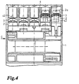
- Fig. 4 the two right-hand clamping screws 2 with a clamping washer 3 are shown in the assembled state, the head 2a of the clamping screw not closer here shown.
- the left three clamping screws show that State in which the clamping screw is turned all the way down and the clamping disc 3 when rotating down by elastic Spread the locking cam 42 outwards from the previous one described fixed position is moved. This screwing in the clamping screw 2 down is only against the spring force of the locking cam 42 possible, this spring force so is dimensioned that in this state the clamping screw 2 itself do not screw in during shaking independently during transport can. 5 are also the fixed contact pieces 6 shown with a nut thread 6a for receiving the Clamping screw 2 are equipped.
- the clamping screws 2 with Clamping disks 3 are in the pre-assembled state shown, the clamping disc 3 between locking cams 42nd the insertion aid and the holding flange of the control room cover 5 is clamped.
- the clamping screw 2 After inserting a cable between Fixed contact piece 6 and clamping disk 3 can then the clamping screw 2 by means of a through the opening 40 of the Insertion aid 4 and through hole 51 of the control room cover 5 in the screw head 2a screwdriver in the direction of the arrow M1 are screwed in, being applied by the Force in the direction of arrow M1 of the edge web 41 with locking cams 42 in Arrow direction P1 is elastically spread outwards, whereby the clamping disc 3 is released and the clamping screw 2 can be turned down until the line is attached.
- the distance a of the locking cams 42 from the contact surface the insertion aid 4 on the switching device 1 is dimensioned that the clamping disc 3 between the underside of the holding flanges 50 of the control room cover 5 (Fig. 3) and the locking cam 42 is easy to pinch.
- the height is also corresponding to dimension the locking web 41.
Landscapes
- Physics & Mathematics (AREA)
- Electromagnetism (AREA)
- Switch Cases, Indication, And Locking (AREA)
- Lock And Its Accessories (AREA)
- Connections By Means Of Piercing Elements, Nuts, Or Screws (AREA)
- Connection Of Plates (AREA)
- Fuses (AREA)
- Clamps And Clips (AREA)
- Gripping Jigs, Holding Jigs, And Positioning Jigs (AREA)
Description
- Figur 1:
- eine schematisierte Explosionsdarstellung eines Schaltgerätes;
- Figur 2:
- eine Einführhilfe in perspektivischer Darstellung für ein Schaltgerät mit zwei Klemmenreihen für je fünf Klemmschrauben;
- Figur 3:
- eine Schaltraumabdeckung passend zu der Einführhilfe gemäß Fig. 2 in perspektivischer Darstellung;
- Figur 4:
- eine teilweise geschnittene Ansicht des Schaltgerätes gemäß Ansicht A nach Fig. 1 mit Einführhilfe und Schaltraumabdeckung gemäß Fig. 2 und 3;
- Figur 5:
- eine teilweise geschnittene Ansicht des Schaltgerätes gemäß Fig. 1 in der Ansicht B bzw. in der Ansicht C gemäß Fig. 4 mit einer Schaltraumabdeckung und Einführhilfe gemäß Fig. 3 und 2.
Claims (3)
- Elektrisches Schaltgerät mit Klemmschraubensicherung, mit mindestens einer Klemmschraube (2) mit Klemmscheibe (3), einer der Anzahl der Klemmschrauben (2) entsprechenden Anzahl von Festkontaktstücken (6), einem äußeren Deckel als Einführhilfe (4), die mit koaxial zu den Klemmschrauben (2) angeordneten Durchgangslöchern (40) und Rastmitteln (41) zum Aufrasten an das Schaltgerät (1) ausgebildet ist, und einem jedem Durchgangsloch (40) zugeordneten Rastnocken (42), durch den die Klemmschraube (2) gegen selbständiges Eindrehen gesichert ist, dadurch gekennzeichnet, daß unterhalb der Einführhilfe (4) ein inneren Deckel als Schaltraumabdeckung (5) angeordnet ist, die mit randseitig sich erstreckenden, den Klemmschrauben (2) zugeordneten Halteflanschen (50) mit je einem koaxial zu den Klemmschrauben (2) und Durchgangslöchern (40) angeordneten Durchsteckloch (51) ausgebildet ist, in denen die Klemmschrauben (2) im hochgeschraubten Zustand verliersicher gehaltert sind, wobei der Außendurchmesser der Klemmscheibe (3) größer und der Durchmesser des Schraubenkopfes (2a) kleiner als der Durchmesser des Durchsteckloches (51) ist, und daß die Einführhilfe (4) an die Durchgangslöcher (40) anschließend randseitig mit nach unten vorstehenden, federnd abspreizbaren und die Halteflansche (50) übergreifenden Randstegen (41) ausgebildet ist, an die innenseitig die Rastnokken vorstehend angeformt sind, und daß jeder Rastnocken (42) einen solchen Abstand (a) von der Anlageebene der Einführhilfe (4) am Schaltgerät (1) aufweist, so daß er unter die im hochgedrehten Zustand der Klemmschraube (2) an der Unterseite des Halteflansches (50) anliegende Klemmscheibe (3) rastet.
- Elektrisches Schaltgerät nach Anspruchl, dadurch gekennzeichnet, daß jeder Klemmschraube (2) je ein einzeln vorstehender Halteflansch (50) mit Durchsteckloch (51) zugeordnet ist.
- Elektrisches Schaltgerät nach einem der Ansprüche 1 oder 2, dadurch gekennzeichnet, daß der Rastnocken (42) am Randsteg (41) mittig jedem Durchgangsloch (40) zugeordnet ist.
Applications Claiming Priority (3)
| Application Number | Priority Date | Filing Date | Title |
|---|---|---|---|
| DE29603754U DE29603754U1 (de) | 1996-02-29 | 1996-02-29 | Elektrisches Schaltgerät mit Klemmschraubensicherung |
| DE29603754U | 1996-02-29 | ||
| PCT/EP1997/000857 WO1997032324A1 (de) | 1996-02-29 | 1997-02-22 | Elektrisches schaltgerät mit klemmschraubensicherung |
Publications (2)
| Publication Number | Publication Date |
|---|---|
| EP0824757A1 EP0824757A1 (de) | 1998-02-25 |
| EP0824757B1 true EP0824757B1 (de) | 2002-04-17 |
Family
ID=8020326
Family Applications (1)
| Application Number | Title | Priority Date | Filing Date |
|---|---|---|---|
| EP97905076A Expired - Lifetime EP0824757B1 (de) | 1996-02-29 | 1997-02-22 | Elektrisches schaltgerät mit klemmschraubensicherung |
Country Status (4)
| Country | Link |
|---|---|
| EP (1) | EP0824757B1 (de) |
| AT (1) | ATE216532T1 (de) |
| DE (2) | DE29603754U1 (de) |
| WO (1) | WO1997032324A1 (de) |
Cited By (1)
| Publication number | Priority date | Publication date | Assignee | Title |
|---|---|---|---|---|
| TWI812795B (zh) * | 2019-10-09 | 2023-08-21 | 鴻海精密工業股份有限公司 | 鎖螺絲智慧防呆裝置 |
Families Citing this family (3)
| Publication number | Priority date | Publication date | Assignee | Title |
|---|---|---|---|---|
| DE29610330U1 (de) * | 1996-06-12 | 1996-08-14 | Siemens AG, 80333 München | Schaltgerät mit Einschraubsicherung |
| DE29703657U1 (de) * | 1997-02-28 | 1997-04-24 | Klöckner-Moeller GmbH, 53115 Bonn | Anschlußklemme mit Schraubensicherung |
| DE102009024867B4 (de) * | 2009-06-09 | 2013-03-28 | Abb Ag | Installationsschaltgerät mit Klemmenabdeckteil |
Family Cites Families (6)
| Publication number | Priority date | Publication date | Assignee | Title |
|---|---|---|---|---|
| DE2448111C3 (de) * | 1974-10-09 | 1982-03-25 | Licentia Patent-Verwaltungs-Gmbh, 6000 Frankfurt | Anordnung zum Anschluß elektrischer Leitungen an ein elektrisches Gerät |
| DE2715572C2 (de) * | 1977-04-07 | 1985-11-14 | Brown, Boveri & Cie Ag, 6800 Mannheim | Schraubensicherung |
| DE2732963C2 (de) * | 1977-07-21 | 1982-10-21 | Starkstrom Gummersbach GmbH, 5277 Marienheide | Schütz |
| DE2909202C2 (de) * | 1979-03-09 | 1983-04-28 | Brown, Boveri & Cie Ag, 6800 Mannheim | Abdeck- und Sicherungskappe für Klemmschrauben an elektrischen Geräten |
| FR2563947B1 (fr) * | 1984-05-02 | 1986-08-22 | Alsthom Cgee | Agencement de raccordement par borne protegee pour appareillage electrique |
| JP2725519B2 (ja) * | 1991-10-01 | 1998-03-11 | 三菱電機株式会社 | 端子台 |
-
1996
- 1996-02-29 DE DE29603754U patent/DE29603754U1/de not_active Expired - Lifetime
-
1997
- 1997-02-22 WO PCT/EP1997/000857 patent/WO1997032324A1/de not_active Ceased
- 1997-02-22 EP EP97905076A patent/EP0824757B1/de not_active Expired - Lifetime
- 1997-02-22 AT AT97905076T patent/ATE216532T1/de not_active IP Right Cessation
- 1997-02-22 DE DE59707018T patent/DE59707018D1/de not_active Expired - Lifetime
Cited By (1)
| Publication number | Priority date | Publication date | Assignee | Title |
|---|---|---|---|---|
| TWI812795B (zh) * | 2019-10-09 | 2023-08-21 | 鴻海精密工業股份有限公司 | 鎖螺絲智慧防呆裝置 |
Also Published As
| Publication number | Publication date |
|---|---|
| DE29603754U1 (de) | 1996-04-25 |
| WO1997032324A1 (de) | 1997-09-04 |
| EP0824757A1 (de) | 1998-02-25 |
| DE59707018D1 (de) | 2002-05-23 |
| ATE216532T1 (de) | 2002-05-15 |
Similar Documents
| Publication | Publication Date | Title |
|---|---|---|
| EP3602708B1 (de) | Anordnung aus einem schaltschrankrahmengestell und einem schaltschranksockel | |
| DE4020581C2 (de) | ||
| EP1186081A1 (de) | Adapterplatte und system zur anbringung eines bauelementes auf eine montageunterlage | |
| EP0054225A1 (de) | Versenkbarer Verschluss für Schaltschranktüren o. dgl. | |
| DE2918289A1 (de) | Elektrisches schaltgeraet, insbesondere nockenschalter | |
| WO2019110414A1 (de) | Adapter zur montage elektrotechnischer bauteile | |
| CH651718A5 (de) | Abdeck- und sicherungskappe fuer klemmschrauben an einem elektrischen geraet. | |
| EP0017124A1 (de) | Elektrisches Gerät, insbesondere Installationsgerät | |
| EP0824757A1 (de) | Elektrisches schaltgerät mit klemmschraubensicherung | |
| DE2448111C3 (de) | Anordnung zum Anschluß elektrischer Leitungen an ein elektrisches Gerät | |
| DE19815602C2 (de) | Befestigungssystem zum Befestigen einer Platte innerhalb eines Gehäuses | |
| DE4007746C2 (de) | Plombiereinrichtung für Baugruppenträger mit steckbaren Baugruppen | |
| DE3639670C2 (de) | Einrichtung zum Plombieren und gleichzeitigen mechanischen Verriegeln eines Deckels an einem Gerät | |
| EP0991158B1 (de) | Geräteaufnahme für eine Unterflurgerätedose | |
| EP0508175A2 (de) | Elektrotechnische Abzweigdose zur Aufputz-Installation | |
| EP0939982B1 (de) | Befestigungsvorrichtung für ein gehäuse | |
| DE3738907C2 (de) | ||
| EP0862242B1 (de) | Anschlussklemme für Schraubensicherung | |
| EP3607615A1 (de) | Halterahmen | |
| DE3129061A1 (de) | Elektrisches installationsgeraet | |
| DE9011441U1 (de) | Vorrichtung zur Befestigung zweier Bauteile | |
| DE753356C (de) | Zaehler- oder Verteilungstafel zus Isolierstoff fuer elektrische Hausstromnetze od. dgl. | |
| WO1994024742A1 (de) | Aufrastbarer klappdeckel | |
| DE102004017517A1 (de) | Sicherungssockel | |
| DE10156876A1 (de) | Einrichtung zum Absichern eines Schraubelements gegen ein unbefugtes Lösen |
Legal Events
| Date | Code | Title | Description |
|---|---|---|---|
| PUAI | Public reference made under article 153(3) epc to a published international application that has entered the european phase |
Free format text: ORIGINAL CODE: 0009012 |
|
| AK | Designated contracting states |
Kind code of ref document: A1 Designated state(s): AT CH DE DK ES FR GB IT LI NL SE |
|
| 17P | Request for examination filed |
Effective date: 19980216 |
|
| RAP1 | Party data changed (applicant data changed or rights of an application transferred) |
Owner name: MOELLER GMBH |
|
| 17Q | First examination report despatched |
Effective date: 20010102 |
|
| GRAG | Despatch of communication of intention to grant |
Free format text: ORIGINAL CODE: EPIDOS AGRA |
|
| GRAG | Despatch of communication of intention to grant |
Free format text: ORIGINAL CODE: EPIDOS AGRA |
|
| GRAH | Despatch of communication of intention to grant a patent |
Free format text: ORIGINAL CODE: EPIDOS IGRA |
|
| REG | Reference to a national code |
Ref country code: GB Ref legal event code: IF02 |
|
| GRAH | Despatch of communication of intention to grant a patent |
Free format text: ORIGINAL CODE: EPIDOS IGRA |
|
| GRAA | (expected) grant |
Free format text: ORIGINAL CODE: 0009210 |
|
| AK | Designated contracting states |
Kind code of ref document: B1 Designated state(s): AT CH DE DK ES FR GB IT LI NL SE |
|
| REF | Corresponds to: |
Ref document number: 216532 Country of ref document: AT Date of ref document: 20020515 Kind code of ref document: T |
|
| REG | Reference to a national code |
Ref country code: CH Ref legal event code: EP |
|
| REF | Corresponds to: |
Ref document number: 59707018 Country of ref document: DE Date of ref document: 20020523 |
|
| REG | Reference to a national code |
Ref country code: CH Ref legal event code: NV Representative=s name: E. BLUM & CO. PATENTANWAELTE |
|
| PG25 | Lapsed in a contracting state [announced via postgrant information from national office to epo] |
Ref country code: SE Free format text: LAPSE BECAUSE OF FAILURE TO SUBMIT A TRANSLATION OF THE DESCRIPTION OR TO PAY THE FEE WITHIN THE PRESCRIBED TIME-LIMIT Effective date: 20020717 Ref country code: DK Free format text: LAPSE BECAUSE OF FAILURE TO SUBMIT A TRANSLATION OF THE DESCRIPTION OR TO PAY THE FEE WITHIN THE PRESCRIBED TIME-LIMIT Effective date: 20020717 |
|
| GBT | Gb: translation of ep patent filed (gb section 77(6)(a)/1977) |
Effective date: 20020709 |
|
| ET | Fr: translation filed | ||
| PG25 | Lapsed in a contracting state [announced via postgrant information from national office to epo] |
Ref country code: ES Free format text: LAPSE BECAUSE OF FAILURE TO SUBMIT A TRANSLATION OF THE DESCRIPTION OR TO PAY THE FEE WITHIN THE PRESCRIBED TIME-LIMIT Effective date: 20021030 |
|
| PLBE | No opposition filed within time limit |
Free format text: ORIGINAL CODE: 0009261 |
|
| STAA | Information on the status of an ep patent application or granted ep patent |
Free format text: STATUS: NO OPPOSITION FILED WITHIN TIME LIMIT |
|
| PG25 | Lapsed in a contracting state [announced via postgrant information from national office to epo] |
Ref country code: AT Free format text: LAPSE BECAUSE OF NON-PAYMENT OF DUE FEES Effective date: 20030222 |
|
| 26N | No opposition filed |
Effective date: 20030120 |
|
| REG | Reference to a national code |
Ref country code: CH Ref legal event code: PFA Owner name: MOELLER GMBH Free format text: MOELLER GMBH#HEIN-MOELLER-STRASSE 7-11#53115 BONN (DE) -TRANSFER TO- MOELLER GMBH#HEIN-MOELLER-STRASSE 7-11#53115 BONN (DE) |
|
| PGFP | Annual fee paid to national office [announced via postgrant information from national office to epo] |
Ref country code: CH Payment date: 20130129 Year of fee payment: 17 |
|
| REG | Reference to a national code |
Ref country code: CH Ref legal event code: PL |
|
| PG25 | Lapsed in a contracting state [announced via postgrant information from national office to epo] |
Ref country code: CH Free format text: LAPSE BECAUSE OF NON-PAYMENT OF DUE FEES Effective date: 20140228 Ref country code: LI Free format text: LAPSE BECAUSE OF NON-PAYMENT OF DUE FEES Effective date: 20140228 |
|
| REG | Reference to a national code |
Ref country code: FR Ref legal event code: PLFP Year of fee payment: 20 |
|
| PGFP | Annual fee paid to national office [announced via postgrant information from national office to epo] |
Ref country code: DE Payment date: 20160302 Year of fee payment: 20 Ref country code: IT Payment date: 20160209 Year of fee payment: 20 |
|
| PGFP | Annual fee paid to national office [announced via postgrant information from national office to epo] |
Ref country code: NL Payment date: 20160205 Year of fee payment: 20 Ref country code: FR Payment date: 20160125 Year of fee payment: 20 Ref country code: GB Payment date: 20160127 Year of fee payment: 20 |
|
| REG | Reference to a national code |
Ref country code: DE Ref legal event code: R071 Ref document number: 59707018 Country of ref document: DE Ref country code: NL Ref legal event code: MK Effective date: 20170221 |
|
| REG | Reference to a national code |
Ref country code: GB Ref legal event code: PE20 Expiry date: 20170221 |
|
| PG25 | Lapsed in a contracting state [announced via postgrant information from national office to epo] |
Ref country code: GB Free format text: LAPSE BECAUSE OF EXPIRATION OF PROTECTION Effective date: 20170221 |