EP0822079A2 - Substrat für einen Tintenstrahlaufzeichnungskopf, Tintenstrahlaufzeichnungskopf mit einem solchen Substrat, Verfahren zum Ansteuern eines solchen Substrates, Tintenstrahlkopfkartusche und Flüssigkeitsausstossapparat - Google Patents
Substrat für einen Tintenstrahlaufzeichnungskopf, Tintenstrahlaufzeichnungskopf mit einem solchen Substrat, Verfahren zum Ansteuern eines solchen Substrates, Tintenstrahlkopfkartusche und Flüssigkeitsausstossapparat Download PDFInfo
- Publication number
- EP0822079A2 EP0822079A2 EP97113147A EP97113147A EP0822079A2 EP 0822079 A2 EP0822079 A2 EP 0822079A2 EP 97113147 A EP97113147 A EP 97113147A EP 97113147 A EP97113147 A EP 97113147A EP 0822079 A2 EP0822079 A2 EP 0822079A2
- Authority
- EP
- European Patent Office
- Prior art keywords
- heat generating
- ink jet
- substrate
- driving
- generating resistors
- Prior art date
- Legal status (The legal status is an assumption and is not a legal conclusion. Google has not performed a legal analysis and makes no representation as to the accuracy of the status listed.)
- Granted
Links
Images


Classifications
-
- B—PERFORMING OPERATIONS; TRANSPORTING
- B41—PRINTING; LINING MACHINES; TYPEWRITERS; STAMPS
- B41J—TYPEWRITERS; SELECTIVE PRINTING MECHANISMS, i.e. MECHANISMS PRINTING OTHERWISE THAN FROM A FORME; CORRECTION OF TYPOGRAPHICAL ERRORS
- B41J2/00—Typewriters or selective printing mechanisms characterised by the printing or marking process for which they are designed
- B41J2/005—Typewriters or selective printing mechanisms characterised by the printing or marking process for which they are designed characterised by bringing liquid or particles selectively into contact with a printing material
- B41J2/01—Ink jet
- B41J2/015—Ink jet characterised by the jet generation process
- B41J2/04—Ink jet characterised by the jet generation process generating single droplets or particles on demand
- B41J2/045—Ink jet characterised by the jet generation process generating single droplets or particles on demand by pressure, e.g. electromechanical transducers
- B41J2/04501—Control methods or devices therefor, e.g. driver circuits, control circuits
- B41J2/04541—Specific driving circuit
-
- B—PERFORMING OPERATIONS; TRANSPORTING
- B41—PRINTING; LINING MACHINES; TYPEWRITERS; STAMPS
- B41J—TYPEWRITERS; SELECTIVE PRINTING MECHANISMS, i.e. MECHANISMS PRINTING OTHERWISE THAN FROM A FORME; CORRECTION OF TYPOGRAPHICAL ERRORS
- B41J2/00—Typewriters or selective printing mechanisms characterised by the printing or marking process for which they are designed
- B41J2/005—Typewriters or selective printing mechanisms characterised by the printing or marking process for which they are designed characterised by bringing liquid or particles selectively into contact with a printing material
- B41J2/01—Ink jet
- B41J2/015—Ink jet characterised by the jet generation process
- B41J2/04—Ink jet characterised by the jet generation process generating single droplets or particles on demand
- B41J2/045—Ink jet characterised by the jet generation process generating single droplets or particles on demand by pressure, e.g. electromechanical transducers
- B41J2/04501—Control methods or devices therefor, e.g. driver circuits, control circuits
- B41J2/04543—Block driving
-
- B—PERFORMING OPERATIONS; TRANSPORTING
- B41—PRINTING; LINING MACHINES; TYPEWRITERS; STAMPS
- B41J—TYPEWRITERS; SELECTIVE PRINTING MECHANISMS, i.e. MECHANISMS PRINTING OTHERWISE THAN FROM A FORME; CORRECTION OF TYPOGRAPHICAL ERRORS
- B41J2/00—Typewriters or selective printing mechanisms characterised by the printing or marking process for which they are designed
- B41J2/005—Typewriters or selective printing mechanisms characterised by the printing or marking process for which they are designed characterised by bringing liquid or particles selectively into contact with a printing material
- B41J2/01—Ink jet
- B41J2/015—Ink jet characterised by the jet generation process
- B41J2/04—Ink jet characterised by the jet generation process generating single droplets or particles on demand
- B41J2/045—Ink jet characterised by the jet generation process generating single droplets or particles on demand by pressure, e.g. electromechanical transducers
- B41J2/04501—Control methods or devices therefor, e.g. driver circuits, control circuits
- B41J2/0458—Control methods or devices therefor, e.g. driver circuits, control circuits controlling heads based on heating elements forming bubbles
-
- B—PERFORMING OPERATIONS; TRANSPORTING
- B41—PRINTING; LINING MACHINES; TYPEWRITERS; STAMPS
- B41J—TYPEWRITERS; SELECTIVE PRINTING MECHANISMS, i.e. MECHANISMS PRINTING OTHERWISE THAN FROM A FORME; CORRECTION OF TYPOGRAPHICAL ERRORS
- B41J2/00—Typewriters or selective printing mechanisms characterised by the printing or marking process for which they are designed
- B41J2/005—Typewriters or selective printing mechanisms characterised by the printing or marking process for which they are designed characterised by bringing liquid or particles selectively into contact with a printing material
- B41J2/01—Ink jet
- B41J2/135—Nozzles
- B41J2/14—Structure thereof only for on-demand ink jet heads
- B41J2/14016—Structure of bubble jet print heads
- B41J2/14072—Electrical connections, e.g. details on electrodes, connecting the chip to the outside...
-
- B—PERFORMING OPERATIONS; TRANSPORTING
- B41—PRINTING; LINING MACHINES; TYPEWRITERS; STAMPS
- B41J—TYPEWRITERS; SELECTIVE PRINTING MECHANISMS, i.e. MECHANISMS PRINTING OTHERWISE THAN FROM A FORME; CORRECTION OF TYPOGRAPHICAL ERRORS
- B41J2/00—Typewriters or selective printing mechanisms characterised by the printing or marking process for which they are designed
- B41J2/005—Typewriters or selective printing mechanisms characterised by the printing or marking process for which they are designed characterised by bringing liquid or particles selectively into contact with a printing material
- B41J2/01—Ink jet
- B41J2/135—Nozzles
- B41J2/14—Structure thereof only for on-demand ink jet heads
- B41J2002/14379—Edge shooter
-
- B—PERFORMING OPERATIONS; TRANSPORTING
- B41—PRINTING; LINING MACHINES; TYPEWRITERS; STAMPS
- B41J—TYPEWRITERS; SELECTIVE PRINTING MECHANISMS, i.e. MECHANISMS PRINTING OTHERWISE THAN FROM A FORME; CORRECTION OF TYPOGRAPHICAL ERRORS
- B41J2202/00—Embodiments of or processes related to ink-jet or thermal heads
- B41J2202/01—Embodiments of or processes related to ink-jet heads
- B41J2202/21—Line printing
Definitions
- the present invention relates to a substrate for use of the ink jet recording head of an ink jet recording apparatus that forms droplets by discharging liquid from orifices.
- the invention also relates to a head using such substrate.
- an ink jet recording method such as disclosed in the specification of Japanese Patent Laid-open Application No. 54-51837, is to cause thermal energy to act upon liquid for obtaining the power source for discharging liquid.
- This is the characteristic aspect of the method that differs from the other types of ink jet recording methods.
- the recording method disclosed in the specification of the Laid-Open Application described above liquid is heated by the activation of thermal energy in order to create bubbles, and by the acting force exerted by the creation of such bubbles, droplets are formed by means of orifices arranged at the leading end of the recording head unit. It is then characterized in that the droplets adhere to a recording member for recording information.
- the recording head applicable to the recording method described above is generally provided with orifices arranged to discharge liquid; a liquid discharging unit having heat activating portions as a part of its structure, in which thermal energy acts upon liquid for discharging droplets, and which are conductively connected with the orifices; a heat generating resistive layer that forms electrothermal transducing elements to generating thermal energy; an upper layer that protects such elements from ink; and a lower layer that accumulates heat.
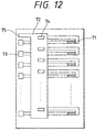
- Fig. 12 is a plan view which shows the conventional example of the structure having electric power wiring arranged on a substrate together with heat generating resistors.
- the conventional example shown in Fig. 12 is a substrate used for the so-called edge shooter type ink jet recording head where liquid is discharged in the direction substantially in parallel with the heat generating surface of heat generating resistors (in the right-hand direction in Fig. 12).
- each heat generating resistor 71 is 150 ⁇ m ⁇ 30 ⁇ m. Eight resistors are produced at arrangement pitches of 200 ⁇ m.
- a protection layer is formed.
- the electrode pads 73 are formed, and also, through holes 74 are provided by making holes on the fetching unit of a common electrode.
- a layer A1 is formed to serve the common electrode.
- the common electrode 72 and the electrode pad 75 for use of external fetching for the common electrode 72 are formed.
- each of the electrode pads 73 is connected with one end of each heat generating resistor 71, while the other end thereof is connected with the common electrode 72 by way of each of the through holes 74 for its shareable use.
- heat is generated when voltage is applied across each of the electrodes 73 and 75.
- Each of the heat generating elements 71 is separated and covered by the flow path walls (not shown) arranged between them. Liquid supplied into the space formed by such flow path walls is discharged from each of the orifices (not shown) by the creation of bubbles brought about by heat generated by each of the heat generating elements.
- a plurality of electrode pads are arranged for the electric power wiring, and the electric power is supplied from outside through each of the electrode pads.
- the heat generating resistors should be arranged more.
- many of such plural numbers of heat generating resistors should be driven simultaneously.
- the driving of the ink jet head that performs discharges by means of bubbling using thermal energy is different from that of the thermal head.
- the pulse width should be made smaller to make the driving power greater.
- the driving current becomes greater accordingly.
- impediments such as the inability to effectuate normal bubbling or disabled bubbling, because the voltage is caused to drop to the extant of the product of the difference that takes place in the electric currents when one heat generating resistor is driven and when many of them are driven at a time and the resistive value of the electric power wires, and also, because this inevitably results in the reduction of voltage applied to the heat generating resistors when many numbers of them are driven at a time.
- the driving voltage When the driving voltage is set at 20 V, which is 1. 3 times the bubbling voltage 15.3 V, the driving voltage 13.8 V, which is 20 V - such reduced voltage of 6.2 V, is lower than the bubbling voltage of 15.3 V. As a result, bubbling becomes impossible. In order to avoid this event, the applied voltage should be raised. However, if the applied voltage is raised, each of the heat generating resistors receives a greater voltage when each of them is driven individually. Therefore, the life of heat generating resistors is made shorter inevitably.
- the wiring may be made a thick film by means of plating techniques or the like in order to make the resistance of the electric power wiring lower.
- a protection layer should be provided, because there is a possibility that the wires are in contact with ink. Therefore, this provision of the protection layer on the thick film makes its upper surface higher than the surface of the heat generating resistors. This, in turn, makes it difficult to form nozzle members on the heat generating resistors, thus presenting another restriction in this respect.
- the nozzles member is in the order of 10 ⁇ m when being formed, while the plated thick film wiring is also in the order of 10 ⁇ m.
- the problem is more conspicuous.
- the size of the substrate should be made larger accordingly.
- the costs of manufacture of the substrate becomes higher for the provision of heat generating elements, which occupy a larger percentage of costs in manufacturing heads.
- the increased number of pads not only invites the reduction of reliability, but also, necessitates making the size of substrate larger.
- the present invention relates to a substrate for an ink jet recording head provided with a plurality of heat generating resistors for discharging ink, wherein the wiring for applying the electric power supplied from outside to the plurality of heat generating resistors is divided into plural numbers, and each of the plurally divided wiring has substantially the same wiring resistive value from each of electrode pads arranged together therewith for receiving the supply of electric power from outside to each of the heat generating resistors.
- a driving element is incorporated within such substrate for driving heat generating resistors.
- the plurally divided wiring is connected in the vicinity of the electrode pad.
- the electrode pads are arranged on the edge portion of such substrate to make the arrangement direction thereof different from the arrangement direction of such plurality of heat generating resistors.
- the present invention relates to a method for driving the substrate structured as described above, which is characterized in that time divisional driving is performed for the heat generating resistors.
- the ink jet head of the present invention uses the substrate for an ink jet recording head structured as described above.
- the ink jet head cartridge of the present invention uses the ink jet head referred to in the preceding paragraph.
- the liquid discharge apparatus of the present invention is provided with the ink jet head described above, and means for supplying driving signals in order to discharge liquid form such ink jet head.
- the resistive values of wiring it is possible to arrange the resistive values of wiring to be almost the same from the electrode pads provided together with the heat generating resistors to receive the supply of electric power from outside up to each of the heat generating resistors, thus making the amount of voltage drop smaller for each of the heat generating resistors when all of them are driven and when each of them is driven, respectively. Then, with the reduction of the numbers of simultaneous driving by the application of the time divisional driving, it is made possible to reduce the divided numbers within the substrate, thus producing more favorable effect. Particularly, it is preferable to perform driving per block of the divided wiring.
- the driving element being incorporated on the substrate, it is made possible to arrange the electric power wiring freely on the driving element, which facilitates both the division of wires and the adjustment of its resistive values.
- the numbers of fetching connections can be reduced by dividing the electric power wiring within the substrate and by connecting them with the electrode pads for external fetching.
- the pads for external fetching on the edge portions perpendicular to the arrangement direction of the heat generating resistors.
- the pad area can be made smaller. Also, it becomes easier to arrange each of the nozzle arrays.
- the electric power wiring can be divided for its effective arrangement to make the size of substrate smaller, leading to the significant reduction of costs of manufacture.
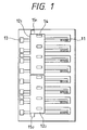
- Fig. 1 is a plan view which shows a substrate in accordance with a first embodiment of the present invention.
- Fig. 2 is a plan view which shows a substrate in accordance with a second embodiment of the present invention.
- Fig. 3 is a plan view which shows a substrate in accordance with a third embodiment of the present invention.
- Fig. 4 is a plan view which shows a substrate in accordance with a fourth embodiment of the present invention.
- Fig. 5 is a plan view which shows a substrate in accordance with a fifth embodiment of the present invention.
- Fig. 6 is a plan view which shows a substrate in accordance with a sixth embodiment of the present invention.
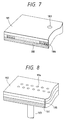
- Fig. 7 is a perspective view which shows the structure of an edge shooter type ink jet head using the substrate in accordance with either one of the first embodiment to the third embodiment.
- Fig. 8 is a perspective view which shows the structure of an edge shooter type ink jet head using the substrate in accordance with either one of the fourth embodiment to the sixth embodiment.
- Fig. 9 is a structural view which schematically shows a liquid discharge apparatus.
- Fig. 10 is a block diagram which shows the apparatus represented in Fig. 9.
- Fig. 11 is a view which shows a liquid discharge recording system.
- Fig. 12 is a plan view which shows the conventional substrate.
- Fig. 1 is a plan view which shows a substrate for use of an ink jet recording head in accordance with a first embodiment of the present invention.
- the present embodiment is a substrate for use of the so-called edge shooter type ink jet recording head that discharges liquid in the direction substantially in parallel with the heat generating surface of the heat generating resistors (in the right-hand direction in Fig. 1) as in the conventional example shown in Fig. 12.
- a reference numeral 11 designates a heat generating resistor; 12, a common electrode (positive electrode); 13, a pad for use of external fetch electrode for the heat generating element 11; 14, a through hole that connects the electrode of the heat generating resistor and the common electrode; and 15, a pad for use of the external fetch electrode for the common electrode 12.
- the substrate of the present embodiment is a substrate for use of an ink jet recording head whose discharging direction is in parallel with the heat generating resistors.
- each heat generating resistor 11 is 150 ⁇ m ⁇ 30 ⁇ m. Eight resistors are produced at arrangement pitches of 200 ⁇ m.
- a protection layer is formed.
- the electrode pads 13 are formed, and also, through holes 14 are provided by making holes on the fetching unit of a common electrode.
- a layer A1 is formed to serve the common electrode.
- the common electrode 12 and the electrode pad 15 for use of external fetching with respect to the common electrode 12 are formed.
- each of the electrode pads 13 is connected with one end of each heat generating resistor 11, while the other end thereof is connected with the common electrode 12 by way of each of the through holes 14 for its shareable use.
- the electrode pads 13 are grounded. Thus, heat is generated when voltage is applied across each of the electrodes 13 and 15.
- Each of the heat generating elements 11 is separated and covered by the flow path walls (not sown) arranged between them. Liquid supplied into the space formed by such flow path walls is discharged from each of the orifices (not shown) by the creation of bubbles brought about by heat generated by each of the heat generating elements.
- the present embodiment differs from the conventional one in that the common electrodes 12 1 and 12 2 are provided by dividing the common electrode 12 into two, each having four heat generating resistors 11 respectively, and that two pads 15 1 and 15 2 are arranged for use of each of external fetch electrodes with respect to the common electrodes 12 1 and 12 2 , respectively.
- the bubbling voltage of the heat generating resistor 71 is 8 V.
- the driving voltage is set at 10 V, which is 1.25 times the bubbling voltage.
- the driving voltage is 0.2 A.
- the common electrodes of the substrate for use of ink jet operation of the present embodiment are divided to make the resistive value of the common electrodes itself lower, and at the same time, to make the difference between the actual driving currents smaller.
- bubbling is effectuated without any problem even when all the heat generating elements are driven at a time.
- an ink jet recording head that uses a higher grade substrate can perform its stabilized recording without making the size of the substrate larger.
- Such ink jet recording head can be manufactured at lower costs.
- Fig. 2 is a view which shows the structure of a second embodiment in accordance with the present invention.
- the heat generating resistors 21, electrode pads 23, and through holes 24 are the same as the heat generating resistors 11, electrode pads 13, and through holes 14 shown in Fig. 1.
- the common electrodes are divided into four common electrodes 22 1 to 22 4 , each corresponding to two heat generating resistors 21. Then, pads 25 1 to 25 4 are arranged for use of external fetch electrodes accordingly.
- each of the common electrodes 22 1 to 22 4 are arranged symmetrically to the center of the arrangement direction of the heat generating resistors 21 (symmetrically to the line that divides Fig. 2 into two in the top to bottom direction).
- the resistive values are determined by the lengths a and c for the common electrodes 22 1 and 22 3 and by the lengths b and d for the common electrodes 22 2 and 22 4 .
- the sheet resistive value is 50 m ⁇ .
- the common electrodes are divided still more. As compared with the first embodiment, it is possible to attempt the further reduction of resistance of the common electrodes.
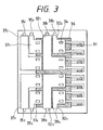
- Fig. 3 is a view which shows the structure of a third embodiment in accordance with the present invention.
- the arrangement and configurational dimensions of the heat generating resistors of the present embodiment are the same as those of the heat generating resistors shown in Fig. 1.
- a driving element 36 is incorporated by means of the NMOS processing on the substrate of the heat generating resistors 31 in order to drive them.
- the driving element 36 is arranged to drive the heat generating resistors 31 in response to data signals inputted from outside to the input terminals (not shown), and also, to clock signals, as well as to signals that indicate the pulse width, among some others.
- the positive voltage and grounding voltage of the driving voltage are provided through the common electrodes in order to drive the heat generating resistors 31.
- the grounding voltage is supplied through the electrode pads 35 1 to 35 4 , common electrodes 31 1 to 37 4 , and through holes 34.
- the positive voltage is supplied likewise through the electrode pads 38 1 to 38 4 , common electrodes 32 1 to 32 4 , and through holes 34.
- the configurational dimensions of the common electrodes 37 1 to 37 4 , and 32 1 to 32 4 are arranged so that the resistive values thereof are made equal to those of the common electrodes 25 1 to 25 4 described in conjunction with the embodiment 2.
- the electrode pads 35 1 to 35 4 , and 38 1 to 38 4 which are arranged together with each of the common electrodes 37 1 to 37 4 , and 32 1 to 32 4 , are arranged on the edge surface substantially perpendicular to the arrangement direction of the heat generating resistors 31.
- Fig. 4 is a view which shows the structure of a fourth embodiment in accordance with the present invention.
- each of the embodiments shown in Fig. 1 to Fig. 3 is the substrate for use of the edge shooter type ink jet recording head where liquid is discharged in the direction substantially in parallel with the heat generating surface of the heat generating resistors
- the present embodiment is a substrate for use of the side shooter type ink jet recording head where liquid is discharged in the direction substantially perpendicular to the heat generating surface of the heat generating resistors.
- Each of the heat generating resistors 41 of the present embodiment has two heat generating resistors, each having the same arrangement and configurational dimensions as those of the heat generating resistor 11 of the embodiment 1.
- Each set that comprises a plurality of heat generating resistors 41 is arranged in a staggered fashion to face each other. Between each of the sets, an ink supply port 48 is open by means of blast processing.
- each heat generating resistor 41 For the set of the heat generating resistors 41 positioned on the left-hand side in Fig. 4, grounding voltage is provided through the electrode pads 45 1 to 45 4 , common electrodes 42 1 to 42 4 , and through holes 44.
- positive voltage is provided through the electrode pads 45 5 to 45 8 , common electrodes 42 5 to 42 8 , and through holes 44.
- the individual driving of each heat generating resistor 41 is performed by means of the electrode pads 43 arranged or each of the heat generating resistors 41 as in the case of the first and second embodiments.
- the configurational dimensions of the common electrodes 42 1 to 42 4 , and 42 5 to 42 8 are arranged so that the resistive values thereof are made equal to those of the common electrodes 25 1 to 25 4 described in conjunction with the embodiment 2, respectively. Also, the electrode pads 42 1 to 42 4 , and 42 5 to 42 8 , which are arranged together with each of the common electrodes 42 1 to 42 4 , and 42 5 to 42 8 , are arranged on the edge surface substantially perpendicular to the arrangement direction of the heat generating resistors 41.
- ink which is provided for the ink supply port 48 from the structure or the like configured by the flow path wall that surrounds each of the heat generating resistors and discharge ports, is supplied onto each of the heat generating resistors 41 through each of the flow paths, and then, by means of bubbling, the ink is discharged vertically above the surface of Fig. 4.
- the structure of the common electrodes of the present embodiment is the same as the embodiment 2 as described above.
- the voltage drop is also the same. Bubbling is performed without any problem for discharging liquid in good condition.
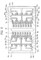
- Fig. 5 is a view which shows the structure of a fifth embodiment in accordance with the present invention.
- the present embodiment is a substrate for use of the side shooter type ink jet recording head where liquid is discharged in the direction substantially perpendicular to the heat generating surface of the heat generating resistors as in the fourth embodiment shown in Fig. 4.
- Each of the heat generating resistors 51 of the present embodiment has two heat generating resistors, each having the same arrangement and configurational dimensions as those of the heat generating resistor 11 of the embodiment 1.
- Each set that comprises a plurality of heat generating resistors 51 is arranged in a staggered fashion to face each other. Between each of the sets, an ink supply port 58 is open by means of blast processing.
- driving elements 56 1 and 56 2 to drive the heat generating resistors 51 are incorporated on the substrate by means of NMOS processing as in the embodiment 3 shown in Fig. 3.
- each of the heat generating resistors 51 is arranged in the staggered fashion in accordance with the present embodiment, and for the set of the heat generating resistors 51 positioned on the left-hand side in Fig. 5, grounding voltage is provided through the electrode pads 55 1 to 55 4 , common electrodes 52 1 to 52 4 , and through holes 54, and positive voltage is provided through the electrode pads 55 5 to 55 8 , common electrodes 52 5 to 52 8 , and through holes 54.
- positive voltage is provided through the electrode pads 55 9 to 55 12 , common electrodes 52 9 to 52 12 , and grounding voltage is provided through the electrode pads 55 13 to 55 16 , common electrodes 52 13 to 52 16 .
- the configurational dimensions of the common electrodes 52 1 to 52 16 are arranged so that the resistive values thereof are made equal to those of the common electrodes 25 1 to 25 4 described in conjunction with the embodiment 2, respectively. Also, the electrode pads 55 1 to 55 16 , which are arranged together with each of the common electrodes 52 1 to 52 16 , are arranged on the edge surface substantially perpendicular to the arrangement direction of the heat generating resistors 51.
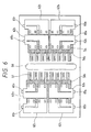
- Fig. 6 is a view which shows the structure of a sixth embodiment in accordance with the present invention.
- the present embodiment is the mode in which the electrode pads are curtailed for use of the external fetching for the common electrodes of the fifth embodiment shown in Fig. 5.
- the common electrodes 62 1 to 62 8 are configured such as to couple the common electrodes 52 1 and 52 2 , 52 3 and 52 4 , 52 5 and 52 6 , 52 7 and 52 8 , 52 9 and 52 10 , 52 11 and 52 12 , 52 13 and 52 14 , 52 15 and 52 16 shown in Fig. 5, respectively.
- electrode pads 65 1 to 65 8 are arranged together with each of the common electrodes 62 1 to 62 8 . All the other structures of the present embodiment are the same as those of the fifth embodiment. Therefore, while applying the same reference marks to such structures as those appearing in Fig. 5, the description thereof will be omitted.
- Each of the common electrodes 62 1 to 62 8 is configured to be in the form that each of the electrodes shown in Fig. 5 is coupled in the vicinity of each of the electrode pads 65 1 to 65 8 . In this way, the amount of voltage drop is made almost equal to that of the fifth embodiment, while curtailing the number of the electrode pads for use of external fetching for the common electrodes by 50%.
- the electrode pads 65 1 to 65 8 for use of driving the driving element are arranged on the edge surface perpendicular to the arrangement direction of the heat generating resistors 61.
- the area where the electrode pads are formed becomes relative sides.
- the terminals are arranged, through which are inputted data signals, clock signals, and signals that indicate the pulse width, among some others. In this way, the pads formed on the substrate become bidirectional to make it possible to reduce the size of the substrate.
- each of the substrates shown in Fig. 6 can be coupled side by side. With such arrangement, it is possible to fabricate a substrate for use of color recording where a pair of supply ports for ink of different colors, such as magenta, cyan, yellow, and black, are provided, for example. In this case, too, the amount of voltage drop can be minimized.
- the driving method it may be possible to cite a method whereby to divide the two heat generating resistors connected with each of the common electrodes into two during the driving cycle.
- the driving current flowing to each of the common electrodes is made equal when all the heat generating resistors are driven and when only one of them is driven. Then, the voltage drop of the common electrodes becomes the same at the time of driving all the heat generating resistors and only one of them.
- the bubbling capability becomes constant irrespective of the number of heat generating resistors to be driven.
- the discharging performance becomes constant, hence making it possible to provide an ink jet recording head having a stabilized printing performance.
- Fig. 7 is a perspective view which shows the structure of an edge shooter type ink jet head using either one of the substrates according to the first to third embodiments shown in Fig. 1 to Fig. 3.
- photosensitive resin is laminated on the substrate 181, which is structured according to either one of the first to third embodiments, and then, the flow path walls are formed by means of photolithographic technique.
- the cover 182 provided with an ink supply port 183 is stacked on it, and cut to form discharge ports, discharge nozzles, and a liquid chamber at a time.
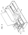
- Fig. 8 is a perspective view which shows the structure of a side shooter type ink jet head using either one of the substrates according to the fourth to sixth embodiments shown in Fig. 4 to Fig. 6.
- photosensitive resin is laminated on the substrate 191, which is structured according to either one of the fourth to sixth embodiments, and then, the flow path walls 195 are formed by means of photolithographic technique.
- the orifice plate 192 provided with an ink supply port 194 is produced by means of electrocasting, and adhesively bonded on the flow path walls 195, hence forming discharge ports, discharge nozzles, and a liquid chamber at a time.
- an ink supply tube 193 is adhesively bonded to the ink supply port of the substrate 191.
- Fig. 9 is a view which schematically shows the liquid discharge apparatus that mounts the ink jet head described above.
- the carriage HC of the liquid discharge apparatus which is described using the ink jet recording apparatus that uses ink as discharging liquid, mounts the head cartridge detachably provided with a liquid tank unit 90 for containing ink and liquid discharge head unit 200, and reciprocates in the width direction of a recording medium, such as recording sheet being carried by recording medium carring means.
- the recording apparatus is provided with a motor 111 as the driving source, gears 112 and 113, and carriage shaft 115 or the like to transfer the driving power from the driving source to the carriage. It is possible to obtain recorded objects having good images by discharging liquid onto various kinds of recording media by use of this recording apparatus and liquid discharging method adopted for the recording apparatus.
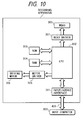
- Fig. 10 is a block diagram which shows the recording apparatus as a whole, which discharges ink for recording by the application of the liquid discharging method and by use of the liquid discharge head of the present invention.
- This recording apparatus receives printing information from a host computer 300 as control signals.
- the printing information is provisionally stored in the input interface 301 of the recording apparatus.
- the printing information is converted to the data that can be processed in the recording apparatus, thus being inputted into the CPU 302 that dually functions as means for supplying head driving signals.
- the CPU 302 processes the inputted data using peripheral units such as RAM 304 and others in accordance with the control program stored in the ROM 303, and converts them to printing data (image data).
- the CPU 302 produces driving data in order to drive the driving motor that carries the recording sheet and the recording head in synchronism with each other for recording the image data in appropriate positions on the recording sheet.
- the image data and driving data are transferred to the head 200 and driving motor 306 through the head driver 307 and the motor driver 305, respectively, which are driven in accordance with the controlled timing to form images.
- the recording medium usable for the recording apparatus described above to provide ink or the like for it there can be named various paper and OHP sheets, plastic materials used for compact disc, ornamental board, or the like, cloths, metallic materials such as aluminum and copper, cattle hide, pig hide, artificial leathers or other leather materials, wood, plywood, bamboo, tiles and other ceramic materials, sponge or other three-dimensional structures.
- a printing apparatus for recording on various paper and OHP sheets there can be named a recording apparatus for use of plastic media to record on compact disc and other plastic materials, a recording apparatus for recording on metallic plates, a recording apparatus for recording on leathers, a recording apparatus for recording on woods, a recording apparatus for recording on ceramics, a recording apparatus for recording on a three-dimensional net structure such as sponge. Also, a textile printing apparatus or the like that records on cloths is included.
- ink jet recording system that uses the liquid discharge head of the present invention as its recording head to perform recording on a recording medium.
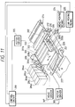
- Fig 11 is a view which schematically illustrate the structure of this ink jet recording system using the liquid discharge head 201 of the present invention described above.
- the liquid discharge head of the present embodiment is a full line type head where a plurality of discharge ports are arranged in the length that corresponds to the recordable width of a recording medium 150 at the intervals (density) of 360 dpi.
- Four liquid discharge heads 201a, 201b, 201c, and 201d are fixedly supported by the holder 202 in parallel to each other at given intervals in the direction X corresponding to four colors, yellow (Y), magenta (M), cyan (C), and black (Bk), respectively.
- a reference numeral 204e designates the bubbling liquid container, and the structure is arranged to supply bubbling liquid to each of the liquid discharge heads.
- head caps 203a to 203d are arranged with sponge or other ink absorbing material contained in them, which cover the discharge ports of the liquid discharge heads in order to maintain each of the heads when recording operation is at rest.
- a reference numeral 206 designates a carrier belt which is arranged to constitute carrier means for carrying each kind of recording medium as described earlier for each of the embodiments.
- This carrier belt 206 is drawn around various rollers at given passage and driven by driving rollers connected with the motor driver 305.
- a pre-processing device 251, and post-processing device 252 are installed on the upstream and downstream of the recording medium carrier passage to perform various processes with respect to the recording medium before and after recording.
- the pre-processing and post-processing are different in the contents of the corresponding process depending on the kinds of recording media and kinds of ink.
- a medium such as metal, plastic, or ceramic
- ultraviolet lays and ozone are irradiated to activate the surface of the medium used, thus improving the adhesion of ink thereto.
- dust particles are easily attracted to the surface thereof to hinder good recording in some cases. Therefore, as the pre-processing device, an ionizer is used to remove static electricity. In this way, dust particles should be removed from the recording medium.
- a pre-processing may be performed to provide a substance selected from among alkali substance, water-soluble substance, synthetic polymer, water-soluble metallic salt, urea, and thiourea for recording on cloths in order to prevent stains on them, while improving its coloring rate.
- the pre-processing is not necessarily limited to those described above. It may be the process to adjust the temperature of a recording medium appropriately to a temperature suited for recording on such medium.
- fixation process is performed as the post-processing to promote the fixation of ink by executing heating process or irradiation of ultraviolet rays, among some others, for the recording medium for which ink has been provided.
- Cleaning process is also performed as a post-processing to rinse off the processing agent provided for the recording medium in the pre-processing but still remaining inactive.
- the description has been made in assumption that a full line head is used as the liquid discharge head, but the present invention is not necessarily limited to the full line head. It may be possible to apply the present invention to such a mode that the smaller liquid discharge head described earlier is carried in the width direction of a recording medium for recording.
- the electric power wiring is divided into plural numbers on and within the substrate for use of an ink jet recording head, while arranging them so that the resistive values of wiring are made almost the same up to the pads for external fetching. In this way, it is possible to make the difference smaller in the voltage drop for the common electrodes when all the heat generating resistors are driven and when only one of them is driven, respectively.
- the numbers of heat generating resistors which are connected with each of the wires and are driven at a time, are arranged to be one heat generating resistor, thus making it possible to eliminate the voltage drop at the time of driving all the heat generating resistors and only one of them. Then, with the reduction of the numbers of simultaneous driving by the application of the time divisional driving, it is made possible to reduce the divided numbers within the substrate, thus producing more favorable effect in this respect.
- the driving element being incorporated on the substrate, it becomes possible to arrange the electric power wiring freely on the driving element, which facilitates both the division of wires and the adjustment of its resistive values.
- the pads for external fetching on the edge portions perpendicular to the arrangement direction of the heat generating resistors.
- the pad area can be made smaller. Also, it becomes easier to arrange each of the nozzle arrays.
- the electric power wiring can be divided for its effective arrangement to make the size of substrate smaller, leading to the significant reduction of costs of manufacture.
- a substrate for an ink jet recording head is provided with a plurality of heat generating resistors for discharging ink.
- the wiring for applying the electric power supplied from outside to the plurality of heat generating resistors is divided into plural numbers, and each of the plurally divided wiring is arranged to provide substantially the same wiring resistive value from each of electrode pads arranged together therewith for receiving the supply of electric power from outside to each of the heat generating resistors.
Priority Applications (1)
| Application Number | Priority Date | Filing Date | Title |
|---|---|---|---|
| EP04017109A EP1481805B1 (de) | 1996-07-31 | 1997-07-30 | Substrat für einen Tintenstrahlaufzeichnungskopf |
Applications Claiming Priority (2)
| Application Number | Priority Date | Filing Date | Title |
|---|---|---|---|
| JP8202245A JPH1044416A (ja) | 1996-07-31 | 1996-07-31 | インクジェット記録ヘッド用基板及びそれを用いたインクジェットヘッド、インクジェットヘッドカートリッジおよび液体吐出装置 |
| JP202245/96 | 1996-07-31 |
Related Child Applications (1)
| Application Number | Title | Priority Date | Filing Date |
|---|---|---|---|
| EP04017109A Division EP1481805B1 (de) | 1996-07-31 | 1997-07-30 | Substrat für einen Tintenstrahlaufzeichnungskopf |
Publications (3)
| Publication Number | Publication Date |
|---|---|
| EP0822079A2 true EP0822079A2 (de) | 1998-02-04 |
| EP0822079A3 EP0822079A3 (de) | 1998-10-07 |
| EP0822079B1 EP0822079B1 (de) | 2006-01-25 |
Family
ID=16454363
Family Applications (2)
| Application Number | Title | Priority Date | Filing Date |
|---|---|---|---|
| EP04017109A Expired - Lifetime EP1481805B1 (de) | 1996-07-31 | 1997-07-30 | Substrat für einen Tintenstrahlaufzeichnungskopf |
| EP97113147A Expired - Lifetime EP0822079B1 (de) | 1996-07-31 | 1997-07-30 | Substrat für einen Tintenstrahlaufzeichnungskopf, Tintenstrahlaufzeichnungskopf mit einem solchen Substrat, Verfahren zum Ansteuern eines solchen Substrates, Tintenstrahlkopfkartusche und Flüssigkeitsausstossapparat |
Family Applications Before (1)
| Application Number | Title | Priority Date | Filing Date |
|---|---|---|---|
| EP04017109A Expired - Lifetime EP1481805B1 (de) | 1996-07-31 | 1997-07-30 | Substrat für einen Tintenstrahlaufzeichnungskopf |
Country Status (4)
| Country | Link |
|---|---|
| US (1) | US6409315B2 (de) |
| EP (2) | EP1481805B1 (de) |
| JP (1) | JPH1044416A (de) |
| DE (2) | DE69735150T2 (de) |
Cited By (1)
| Publication number | Priority date | Publication date | Assignee | Title |
|---|---|---|---|---|
| EP1527878A1 (de) * | 2003-10-31 | 2005-05-04 | Canon Kabushiki Kaisha | Tintenstrahlaufzeichnungskopfsubstrat , Tintenstrahlaufzeichnungskopf und Tintenstrahlaufzeichnungsgerät |
Families Citing this family (27)
| Publication number | Priority date | Publication date | Assignee | Title |
|---|---|---|---|---|
| JP4557386B2 (ja) | 2000-07-10 | 2010-10-06 | キヤノン株式会社 | 記録ヘッド用基板の製造方法 |
| US6612672B2 (en) * | 2000-12-04 | 2003-09-02 | Canon Kabushiki Kaisha | Ink jet printing apparatus and ink jet printing method |
| JP4632386B2 (ja) * | 2000-12-21 | 2011-02-16 | キヤノン株式会社 | 液体吐出記録ヘッド |
| JP4537159B2 (ja) * | 2003-09-08 | 2010-09-01 | キヤノン株式会社 | 液体吐出ヘッド用半導体装置、液体吐出へッド及び液体吐出装置 |
| US6976752B2 (en) * | 2003-10-28 | 2005-12-20 | Lexmark International, Inc. | Ink jet printer with resistance compensation circuit |
| US7152951B2 (en) * | 2004-02-10 | 2006-12-26 | Lexmark International, Inc. | High resolution ink jet printhead |
| JP4886187B2 (ja) | 2004-12-15 | 2012-02-29 | キヤノン株式会社 | インクジェット記録ヘッド用基板および該基板を用いるインクジェット記録ヘッド |
| JP4845415B2 (ja) | 2005-04-18 | 2011-12-28 | キヤノン株式会社 | インクジェット記録ヘッド |
| US7290864B2 (en) * | 2005-09-30 | 2007-11-06 | Lexmark International, Inc. | Heater chips with a reduced number of bondpads |
| JP4901414B2 (ja) * | 2006-02-02 | 2012-03-21 | 株式会社リコー | 液滴吐出ヘッド用回路基板、液滴吐出ヘッド、液体カートリッジ、液滴吐出記録装置、及びライン型液滴吐出記録装置 |
| US7905577B2 (en) * | 2006-12-15 | 2011-03-15 | Canon Kabushiki Kaisha | Printhead substrate having electrothermal transducers arranged at high density, printhead, and printing apparatus |
| JP5040375B2 (ja) * | 2007-03-08 | 2012-10-03 | ブラザー工業株式会社 | 駆動装置及び液滴吐出装置 |
| KR100894373B1 (ko) | 2007-03-22 | 2009-04-22 | 실버브룩 리서치 피티와이 리미티드 | 프린트헤드 모듈 |
| JP5197178B2 (ja) * | 2007-06-27 | 2013-05-15 | キヤノン株式会社 | インクジェット記録ヘッド用基板およびインクジェット記録ヘッド |
| EP2116379B1 (de) | 2008-05-08 | 2012-02-29 | Canon Kabushiki Kaisha | Druckelementsubstrat, Druckkopf und Druckvorrichtung |
| US8231195B2 (en) * | 2008-05-08 | 2012-07-31 | Canon Kabushiki Kaisha | Print element substrate, printhead, and printing apparatus |
| US8167411B2 (en) * | 2008-05-08 | 2012-05-01 | Canon Kabushiki Kaisha | Print element substrate, inkjet printhead, and printing apparatus |
| US8075102B2 (en) | 2008-06-19 | 2011-12-13 | Canon Kabushiki Kaisha | Substrate for ink jet head and ink jet head |
| JP5679679B2 (ja) * | 2010-02-26 | 2015-03-04 | 京セラ株式会社 | 光プリントヘッドおよびそれを用いた画像形成装置 |
| JP5051261B2 (ja) | 2010-03-31 | 2012-10-17 | ブラザー工業株式会社 | 補強接点の接続状態検査方法、及び、圧電アクチュエータ装置 |
| JP5539030B2 (ja) * | 2010-05-28 | 2014-07-02 | キヤノン株式会社 | 半導体装置、液体吐出ヘッド、液体吐出ヘッドカートリッジ及び液体吐出装置 |
| JP6376829B2 (ja) * | 2014-05-09 | 2018-08-22 | キヤノン株式会社 | 液体吐出用基板、液体吐出用ヘッド、および、記録装置 |
| US9597893B2 (en) | 2015-01-06 | 2017-03-21 | Canon Kabushiki Kaisha | Element substrate and liquid discharge head |
| JP6470570B2 (ja) | 2015-01-06 | 2019-02-13 | キヤノン株式会社 | 素子基板、液体吐出ヘッド及び記録装置 |
| JP6806464B2 (ja) | 2016-05-30 | 2021-01-06 | キヤノン株式会社 | 記録素子基板、液体吐出ヘッドおよび液体吐出装置 |
| US10308018B2 (en) | 2016-10-25 | 2019-06-04 | Canon Kabushiki Kaisha | Printing apparatus and method of controlling printhead |
| CN115179654B (zh) * | 2022-08-15 | 2024-03-01 | 极海微电子股份有限公司 | 半导体器件、液体排出头、墨盒和打印装置 |
Citations (3)
| Publication number | Priority date | Publication date | Assignee | Title |
|---|---|---|---|---|
| JPS6213367A (ja) * | 1985-07-12 | 1987-01-22 | Sony Corp | サ−マルヘツド |
| DE3840412A1 (de) * | 1988-11-30 | 1990-02-15 | Siemens Ag | Anordnung fuer einen in duennschichttechnik aufgebauten tintendruckkopf |
| EP0532877A2 (de) * | 1991-08-02 | 1993-03-24 | Canon Kabushiki Kaisha | Aufzeichnungsgerät, Aufzeichnungskopf und Substrat |
Family Cites Families (24)
| Publication number | Priority date | Publication date | Assignee | Title |
|---|---|---|---|---|
| JPS5451837A (en) | 1977-09-30 | 1979-04-24 | Ricoh Co Ltd | Ink jet head device |
| JPS5453837A (en) | 1977-10-06 | 1979-04-27 | Fujitsu Ltd | Memory error report system |
| US4296421A (en) * | 1978-10-26 | 1981-10-20 | Canon Kabushiki Kaisha | Ink jet recording device using thermal propulsion and mechanical pressure changes |
| AU531269B2 (en) * | 1979-03-06 | 1983-08-18 | Canon Kabushiki Kaisha | Ink jet printer |
| JPS5772867A (en) | 1980-10-23 | 1982-05-07 | Canon Inc | Liquid injecting recording apparatus |
| JPS60159062A (ja) | 1984-01-31 | 1985-08-20 | Canon Inc | 液体噴射記録ヘツド |
| US4719478A (en) | 1985-09-27 | 1988-01-12 | Canon Kabushiki Kaisha | Heat generating resistor, recording head using such resistor and drive method therefor |
| US4965594A (en) | 1986-02-28 | 1990-10-23 | Canon Kabushiki Kaisha | Liquid jet recording head with laminated heat resistive layers on a support member |
| JPH0729433B2 (ja) | 1986-03-05 | 1995-04-05 | キヤノン株式会社 | 液体噴射記録ヘツドの作成方法 |
| JPH0717065B2 (ja) * | 1986-11-27 | 1995-03-01 | 富士ゼロックス株式会社 | インクジエツト記録装置 |
| EP0570021B1 (de) | 1987-12-02 | 1997-03-19 | Canon Kabushiki Kaisha | Trägerschicht für Farbstrahlkopf, Herstellungsverfahren und Farbstrahlgerät versehen mit solch einem Kopf |
| JP2846636B2 (ja) | 1987-12-02 | 1999-01-13 | キヤノン株式会社 | インクジェット記録ヘッド用基板の作製方法 |
| JPH01242262A (ja) * | 1988-03-24 | 1989-09-27 | Nec Corp | マルチノズルインクジェットヘッド |
| US5140345A (en) | 1989-03-01 | 1992-08-18 | Canon Kabushiki Kaisha | Method of manufacturing a substrate for a liquid jet recording head and substrate manufactured by the method |
| US5211754A (en) | 1989-03-01 | 1993-05-18 | Canon Kabushiki Kaisha | Method of manufacturing a substrate for a liquid jet recording head, substrate manufactured by the method, liquid jet recording head formed by use of the substrate, and liquid jet recording apparatus having the head |
| JP2949758B2 (ja) * | 1990-02-20 | 1999-09-20 | 富士通株式会社 | アクティブマトリクス型液晶表示装置とその製造方法 |
| US5159353A (en) * | 1991-07-02 | 1992-10-27 | Hewlett-Packard Company | Thermal inkjet printhead structure and method for making the same |
| JP3178011B2 (ja) * | 1991-07-11 | 2001-06-18 | セイコーエプソン株式会社 | マトリクス型表示パネル形成用の基板 |
| JPH05338208A (ja) * | 1992-06-10 | 1993-12-21 | Fuji Xerox Co Ltd | サーマルヘッドの駆動方法 |
| JP3264694B2 (ja) | 1992-06-16 | 2002-03-11 | キヤノン株式会社 | インクジェット記録ヘッドおよびインクジェット記録方法 |
| JP3229472B2 (ja) * | 1993-12-22 | 2001-11-19 | キヤノン株式会社 | インクジェット記録ヘッドおよびインクジェット記録装置 |
| JPH07186378A (ja) * | 1993-12-27 | 1995-07-25 | Canon Inc | 液体噴射記録ヘッドおよび記録装置 |
| JPH07323537A (ja) * | 1994-05-31 | 1995-12-12 | Canon Inc | インクジェット記録ヘッド |
| JPH08258292A (ja) * | 1995-03-20 | 1996-10-08 | Canon Inc | 記録装置 |
-
1996
- 1996-07-31 JP JP8202245A patent/JPH1044416A/ja active Pending
-
1997
- 1997-07-28 US US08/901,661 patent/US6409315B2/en not_active Expired - Lifetime
- 1997-07-30 DE DE69735150T patent/DE69735150T2/de not_active Expired - Lifetime
- 1997-07-30 EP EP04017109A patent/EP1481805B1/de not_active Expired - Lifetime
- 1997-07-30 EP EP97113147A patent/EP0822079B1/de not_active Expired - Lifetime
- 1997-07-30 DE DE69740046T patent/DE69740046D1/de not_active Expired - Lifetime
Patent Citations (3)
| Publication number | Priority date | Publication date | Assignee | Title |
|---|---|---|---|---|
| JPS6213367A (ja) * | 1985-07-12 | 1987-01-22 | Sony Corp | サ−マルヘツド |
| DE3840412A1 (de) * | 1988-11-30 | 1990-02-15 | Siemens Ag | Anordnung fuer einen in duennschichttechnik aufgebauten tintendruckkopf |
| EP0532877A2 (de) * | 1991-08-02 | 1993-03-24 | Canon Kabushiki Kaisha | Aufzeichnungsgerät, Aufzeichnungskopf und Substrat |
Non-Patent Citations (1)
| Title |
|---|
| PATENT ABSTRACTS OF JAPAN vol. 011, no. 188 (M-599), 17 June 1987 & JP 62 013367 A (SONY CORP), 22 January 1987 * |
Cited By (1)
| Publication number | Priority date | Publication date | Assignee | Title |
|---|---|---|---|---|
| EP1527878A1 (de) * | 2003-10-31 | 2005-05-04 | Canon Kabushiki Kaisha | Tintenstrahlaufzeichnungskopfsubstrat , Tintenstrahlaufzeichnungskopf und Tintenstrahlaufzeichnungsgerät |
Also Published As
| Publication number | Publication date |
|---|---|
| EP1481805B1 (de) | 2010-11-03 |
| EP1481805A2 (de) | 2004-12-01 |
| DE69735150T2 (de) | 2006-11-30 |
| JPH1044416A (ja) | 1998-02-17 |
| EP1481805A3 (de) | 2005-03-09 |
| DE69735150D1 (de) | 2006-04-13 |
| US20010052916A1 (en) | 2001-12-20 |
| DE69740046D1 (de) | 2010-12-16 |
| EP0822079A3 (de) | 1998-10-07 |
| US6409315B2 (en) | 2002-06-25 |
| EP0822079B1 (de) | 2006-01-25 |
Similar Documents
| Publication | Publication Date | Title |
|---|---|---|
| EP1481805B1 (de) | Substrat für einen Tintenstrahlaufzeichnungskopf | |
| EP1060891B1 (de) | Aufzeichnungskopf und Aufzeichnungsgerät | |
| EP0710560B1 (de) | Verfahren und Vorrichtung zum Tintenstrahldrucken | |
| EP0390202B1 (de) | Tintenstrahlaufzeichnungskopf, Betriebsart und Tintenstrahlaufzeichnungsgerät | |
| US5771052A (en) | Single pass ink jet printer with offset ink jet modules | |
| US5281980A (en) | Ink jet recording head | |
| US6099109A (en) | Liquid-ejecting head and method of manufacturing the same | |
| EP1116589B1 (de) | Tintenstrahldruckverfahren und Tintenstrahldrucker | |
| EP0707965B1 (de) | Substrat für einen Flüssigkeitsstrahlkopf, Flüssigkeitsstrahlkopf zur Verwendung desselben und diesen verwendender Flüssigkeitsstrahlapparat | |
| US6137506A (en) | Ink jet recording head with a plurality of orifice plates | |
| JP3554113B2 (ja) | 液体吐出ヘッド、液体吐出ヘッドの製造方法、液体吐出装置、および記録システム | |
| EP0894627B1 (de) | Flüssigkeitsstrahlkopf, Druckkopfkassette, Flüssigkeitsstrahlaufzeichnungsvorrichtung, und Flüssigkeitsstrahlkopfherstellungsverfahren | |
| JP3563883B2 (ja) | インクジェットヘッド及びインクジェットヘッド用基板 | |
| JPH0789098A (ja) | インクジェット記録装置 | |
| JPH07195690A (ja) | インクジェット記録ヘッドおよびインクジェット記録装置 | |
| JPH0789072A (ja) | インクジェットヘッド用基体、インクジェットヘッド、該インクジェットヘッド用基体の製造方法、および該インクジェットヘッドの製造方法 | |
| JPH07314680A (ja) | 液体噴射ヘッド、該液体噴射ヘッドを有するヘッドカートリッジ、液体噴射装置および液体噴射ヘッドの製造方法 | |
| JPH1076665A (ja) | 液体噴射ヘッド及びこれを用いた記録方法 |
Legal Events
| Date | Code | Title | Description |
|---|---|---|---|
| PUAI | Public reference made under article 153(3) epc to a published international application that has entered the european phase |
Free format text: ORIGINAL CODE: 0009012 |
|
| AK | Designated contracting states |
Kind code of ref document: A2 Designated state(s): DE ES FR GB IT |
|
| AX | Request for extension of the european patent |
Free format text: AL;LT;LV;RO;SI |
|
| PUAL | Search report despatched |
Free format text: ORIGINAL CODE: 0009013 |
|
| AK | Designated contracting states |
Kind code of ref document: A3 Designated state(s): AT BE CH DE DK ES FI FR GB GR IE IT LI LU MC NL PT SE |
|
| 17P | Request for examination filed |
Effective date: 19990222 |
|
| AKX | Designation fees paid |
Free format text: DE ES FR GB IT |
|
| 17Q | First examination report despatched |
Effective date: 20010529 |
|
| GRAP | Despatch of communication of intention to grant a patent |
Free format text: ORIGINAL CODE: EPIDOSNIGR1 |
|
| GRAS | Grant fee paid |
Free format text: ORIGINAL CODE: EPIDOSNIGR3 |
|
| GRAA | (expected) grant |
Free format text: ORIGINAL CODE: 0009210 |
|
| AK | Designated contracting states |
Kind code of ref document: B1 Designated state(s): DE ES FR GB IT |
|
| REG | Reference to a national code |
Ref country code: GB Ref legal event code: FG4D |
|
| REF | Corresponds to: |
Ref document number: 69735150 Country of ref document: DE Date of ref document: 20060413 Kind code of ref document: P |
|
| PG25 | Lapsed in a contracting state [announced via postgrant information from national office to epo] |
Ref country code: ES Free format text: LAPSE BECAUSE OF FAILURE TO SUBMIT A TRANSLATION OF THE DESCRIPTION OR TO PAY THE FEE WITHIN THE PRESCRIBED TIME-LIMIT Effective date: 20060506 |
|
| ET | Fr: translation filed | ||
| PLBE | No opposition filed within time limit |
Free format text: ORIGINAL CODE: 0009261 |
|
| STAA | Information on the status of an ep patent application or granted ep patent |
Free format text: STATUS: NO OPPOSITION FILED WITHIN TIME LIMIT |
|
| 26N | No opposition filed |
Effective date: 20061026 |
|
| PGFP | Annual fee paid to national office [announced via postgrant information from national office to epo] |
Ref country code: FR Payment date: 20130726 Year of fee payment: 17 |
|
| PGFP | Annual fee paid to national office [announced via postgrant information from national office to epo] |
Ref country code: IT Payment date: 20130709 Year of fee payment: 17 |
|
| REG | Reference to a national code |
Ref country code: FR Ref legal event code: ST Effective date: 20150331 |
|
| PG25 | Lapsed in a contracting state [announced via postgrant information from national office to epo] |
Ref country code: IT Free format text: LAPSE BECAUSE OF NON-PAYMENT OF DUE FEES Effective date: 20140730 |
|
| PG25 | Lapsed in a contracting state [announced via postgrant information from national office to epo] |
Ref country code: FR Free format text: LAPSE BECAUSE OF NON-PAYMENT OF DUE FEES Effective date: 20140731 |
|
| PGFP | Annual fee paid to national office [announced via postgrant information from national office to epo] |
Ref country code: GB Payment date: 20150727 Year of fee payment: 19 Ref country code: DE Payment date: 20150731 Year of fee payment: 19 |
|
| REG | Reference to a national code |
Ref country code: DE Ref legal event code: R119 Ref document number: 69735150 Country of ref document: DE |
|
| GBPC | Gb: european patent ceased through non-payment of renewal fee |
Effective date: 20160730 |
|
| PG25 | Lapsed in a contracting state [announced via postgrant information from national office to epo] |
Ref country code: DE Free format text: LAPSE BECAUSE OF NON-PAYMENT OF DUE FEES Effective date: 20170201 |
|
| PG25 | Lapsed in a contracting state [announced via postgrant information from national office to epo] |
Ref country code: GB Free format text: LAPSE BECAUSE OF NON-PAYMENT OF DUE FEES Effective date: 20160730 |