EP0818583A1 - Schwenkbarer hydraulischer bagger - Google Patents
Schwenkbarer hydraulischer bagger Download PDFInfo
- Publication number
- EP0818583A1 EP0818583A1 EP97900788A EP97900788A EP0818583A1 EP 0818583 A1 EP0818583 A1 EP 0818583A1 EP 97900788 A EP97900788 A EP 97900788A EP 97900788 A EP97900788 A EP 97900788A EP 0818583 A1 EP0818583 A1 EP 0818583A1
- Authority
- EP
- European Patent Office
- Prior art keywords
- boom
- work front
- swing
- hydraulic excavator
- turn
- Prior art date
- Legal status (The legal status is an assumption and is not a legal conclusion. Google has not performed a legal analysis and makes no representation as to the accuracy of the status listed.)
- Withdrawn
Links
Images


Classifications
-
- E—FIXED CONSTRUCTIONS
- E02—HYDRAULIC ENGINEERING; FOUNDATIONS; SOIL SHIFTING
- E02F—DREDGING; SOIL-SHIFTING
- E02F3/00—Dredgers; Soil-shifting machines
- E02F3/04—Dredgers; Soil-shifting machines mechanically-driven
- E02F3/28—Dredgers; Soil-shifting machines mechanically-driven with digging tools mounted on a dipper- or bucket-arm, i.e. there is either one arm or a pair of arms, e.g. dippers, buckets
- E02F3/30—Dredgers; Soil-shifting machines mechanically-driven with digging tools mounted on a dipper- or bucket-arm, i.e. there is either one arm or a pair of arms, e.g. dippers, buckets with a dipper-arm pivoted on a cantilever beam, i.e. boom
- E02F3/32—Dredgers; Soil-shifting machines mechanically-driven with digging tools mounted on a dipper- or bucket-arm, i.e. there is either one arm or a pair of arms, e.g. dippers, buckets with a dipper-arm pivoted on a cantilever beam, i.e. boom working downwardly and towards the machine, e.g. with backhoes
-
- E—FIXED CONSTRUCTIONS
- E02—HYDRAULIC ENGINEERING; FOUNDATIONS; SOIL SHIFTING
- E02F—DREDGING; SOIL-SHIFTING
- E02F3/00—Dredgers; Soil-shifting machines
- E02F3/04—Dredgers; Soil-shifting machines mechanically-driven
- E02F3/28—Dredgers; Soil-shifting machines mechanically-driven with digging tools mounted on a dipper- or bucket-arm, i.e. there is either one arm or a pair of arms, e.g. dippers, buckets
- E02F3/30—Dredgers; Soil-shifting machines mechanically-driven with digging tools mounted on a dipper- or bucket-arm, i.e. there is either one arm or a pair of arms, e.g. dippers, buckets with a dipper-arm pivoted on a cantilever beam, i.e. boom
- E02F3/301—Dredgers; Soil-shifting machines mechanically-driven with digging tools mounted on a dipper- or bucket-arm, i.e. there is either one arm or a pair of arms, e.g. dippers, buckets with a dipper-arm pivoted on a cantilever beam, i.e. boom with more than two arms (boom included), e.g. two-part boom with additional dipper-arm
-
- E—FIXED CONSTRUCTIONS
- E02—HYDRAULIC ENGINEERING; FOUNDATIONS; SOIL SHIFTING
- E02F—DREDGING; SOIL-SHIFTING
- E02F3/00—Dredgers; Soil-shifting machines
- E02F3/04—Dredgers; Soil-shifting machines mechanically-driven
- E02F3/28—Dredgers; Soil-shifting machines mechanically-driven with digging tools mounted on a dipper- or bucket-arm, i.e. there is either one arm or a pair of arms, e.g. dippers, buckets
- E02F3/30—Dredgers; Soil-shifting machines mechanically-driven with digging tools mounted on a dipper- or bucket-arm, i.e. there is either one arm or a pair of arms, e.g. dippers, buckets with a dipper-arm pivoted on a cantilever beam, i.e. boom
- E02F3/32—Dredgers; Soil-shifting machines mechanically-driven with digging tools mounted on a dipper- or bucket-arm, i.e. there is either one arm or a pair of arms, e.g. dippers, buckets with a dipper-arm pivoted on a cantilever beam, i.e. boom working downwardly and towards the machine, e.g. with backhoes
- E02F3/325—Backhoes of the miniature type
-
- E—FIXED CONSTRUCTIONS
- E02—HYDRAULIC ENGINEERING; FOUNDATIONS; SOIL SHIFTING
- E02F—DREDGING; SOIL-SHIFTING
- E02F3/00—Dredgers; Soil-shifting machines
- E02F3/04—Dredgers; Soil-shifting machines mechanically-driven
- E02F3/28—Dredgers; Soil-shifting machines mechanically-driven with digging tools mounted on a dipper- or bucket-arm, i.e. there is either one arm or a pair of arms, e.g. dippers, buckets
- E02F3/36—Component parts
- E02F3/38—Cantilever beams, i.e. booms;, e.g. manufacturing processes, forms, geometry or materials used for booms; Dipper-arms, e.g. manufacturing processes, forms, geometry or materials used for dipper-arms; Bucket-arms
- E02F3/382—Connections to the frame; Supports for booms or arms
- E02F3/384—Connections to the frame; Supports for booms or arms the boom being pivotable relative to the frame about a vertical axis
-
- E—FIXED CONSTRUCTIONS
- E02—HYDRAULIC ENGINEERING; FOUNDATIONS; SOIL SHIFTING
- E02F—DREDGING; SOIL-SHIFTING
- E02F3/00—Dredgers; Soil-shifting machines
- E02F3/04—Dredgers; Soil-shifting machines mechanically-driven
- E02F3/28—Dredgers; Soil-shifting machines mechanically-driven with digging tools mounted on a dipper- or bucket-arm, i.e. there is either one arm or a pair of arms, e.g. dippers, buckets
- E02F3/36—Component parts
- E02F3/38—Cantilever beams, i.e. booms;, e.g. manufacturing processes, forms, geometry or materials used for booms; Dipper-arms, e.g. manufacturing processes, forms, geometry or materials used for dipper-arms; Bucket-arms
- E02F3/382—Connections to the frame; Supports for booms or arms
- E02F3/386—Connections to the frame; Supports for booms or arms the boom being laterally shiftable relative to the frame
-
- E—FIXED CONSTRUCTIONS
- E02—HYDRAULIC ENGINEERING; FOUNDATIONS; SOIL SHIFTING
- E02F—DREDGING; SOIL-SHIFTING
- E02F3/00—Dredgers; Soil-shifting machines
- E02F3/04—Dredgers; Soil-shifting machines mechanically-driven
- E02F3/96—Dredgers; Soil-shifting machines mechanically-driven with arrangements for alternate or simultaneous use of different digging elements
- E02F3/963—Arrangements on backhoes for alternate use of different tools
- E02F3/964—Arrangements on backhoes for alternate use of different tools of several tools mounted on one machine
-
- E—FIXED CONSTRUCTIONS
- E02—HYDRAULIC ENGINEERING; FOUNDATIONS; SOIL SHIFTING
- E02F—DREDGING; SOIL-SHIFTING
- E02F9/00—Component parts of dredgers or soil-shifting machines, not restricted to one of the kinds covered by groups E02F3/00 - E02F7/00
- E02F9/08—Superstructures; Supports for superstructures
- E02F9/0808—Improving mounting or assembling, e.g. frame elements, disposition of all the components on the superstructures
-
- E—FIXED CONSTRUCTIONS
- E02—HYDRAULIC ENGINEERING; FOUNDATIONS; SOIL SHIFTING
- E02F—DREDGING; SOIL-SHIFTING
- E02F9/00—Component parts of dredgers or soil-shifting machines, not restricted to one of the kinds covered by groups E02F3/00 - E02F7/00
- E02F9/08—Superstructures; Supports for superstructures
- E02F9/0833—Improving access, e.g. for maintenance, steps for improving driver's access, handrails
-
- E—FIXED CONSTRUCTIONS
- E02—HYDRAULIC ENGINEERING; FOUNDATIONS; SOIL SHIFTING
- E02F—DREDGING; SOIL-SHIFTING
- E02F9/00—Component parts of dredgers or soil-shifting machines, not restricted to one of the kinds covered by groups E02F3/00 - E02F7/00
- E02F9/08—Superstructures; Supports for superstructures
- E02F9/0858—Arrangement of component parts installed on superstructures not otherwise provided for, e.g. electric components, fenders, air-conditioning units
- E02F9/0891—Lids or bonnets or doors or details thereof
Definitions
- the present invention relates to a hydraulic excavator comprising a traveling carriage and a turning structure turnably mounted on the traveling carriage, and more particularly to a swing type hydraulic excavator with a boom capable of swinging to the left and right in a position on the front end side of the turning structure to carry out, e.g., digging of a side trench.
- the upper cover is required to have a necessary minimum volume enough to install the equipments.
- the longitudinal groove into which a back portion of the boom comes when the boom is lifted rearwardly upward is formed in the upper cover.
- the boom of the offset type hydraulic excavator is just lifted up and down, the presence of the longitudinal groove brings about a so small reduction in the volume defined by the upper cover that the necessary equipments can be installed inside the upper cover.
- the boom can be inclined rearward to a large extent, it is possible to reduce the radius of turn of the work front in its minimum-turn posture.
- the offset type hydraulic excavator also has the problems below.
- swing type hydraulic excavators as disclosed in the above (2) and (3) have no complex parallel link mechanisms in the upper portion of the work front, do not suffer from such an increase weight as resulted in the offset type, and are free from the problems caused by the offset movement of the arm and the bucket.
- An object of the present invention is to provide a swing type hydraulic excavator having no complex parallel link mechanism in an upper portion of a work front, which can minimize a reduction in volume defined by an upper cover and can reduce the radius of turn of the work front in its minimum-turn posture.
- a swing type hydraulic excavator comprising an under traveling carriage, a turning frame turnably mounted above the under traveling carriage, a swing post attached to the turning frame rotatably in the horizontal direction about a vertical pin, a work front attached to the swing post rotatably in the vertical direction and including a boom, a cab provided on the turning frame on one side in the direction of body width, and an upper cover covering most area over the turning frame except the cab and housing equipments such as a prime mover, a hydraulic pump and a tank therein, the boom of the work front being inclined rearward to a position laterally of the cab when the boom is maximally lifted upward to take a minimum-turn position of the work front where the boom is closest to the upper cover, thereby reducing a radius of turn of the work front in the minimum-turn posture, wherein a curved portion for avoiding interference with the work front is formed in an end portion of the upper cover on the side near the work front, and the curved portion
- the back surface of the boom draws a locus substantially in the form of, e.g., an inverted cone, having a center axis aligned with the axis of the vertical pin, because the boom is vertically rotatably attached to the swing post which is attached to the turning frame turnably about the vertical pin. Accordingly, when the boom is going to be inclined rearward to a large extent in the minimum-turn posture, the boom and the upper cover would interfere with each other somewhere the above locus if the upper cover has no recessed surface portion.
- the recessed surface which is configured to have the center axis aligned with the axis of the vertical pin and extend along the above locus while defining a gap with respect to the above locus, is formed in the curved portion which is formed in the end portion of the upper cover on the side near the work front, so that the boom is prevented from interfering with the upper cover even when the boom is inclined rearward to a large extent in the minimum-turn posture.
- the radius of turn of the work front in the minimum-turn posture can be reduce by inclining the boom rearward to a large extent in the minimum-turn posture.
- the volume defined by the upper cover is reduced minimally, i.e., just in amount corresponding to the provision of the recessed surface formed in the curved portion. Therefore, a space sufficient for installing necessary equipments can be ensured inside the upper cover.
- the turning frame is dimensioned to be turnable within the body width of the under traveling carriage or within a diameter close to the body width, and the work front is turnable within an area defined by the radius of turn of the turning frame.
- the present invention is more effective because the space defined by the upper cover is more restricted.
- the boom of the work front is a two-piece boom made up of a lower boom and an upper boom
- the work front includes a cross rod having one end coupled to the upper boom for changing an angle between the upper boom and the lower boom depending on a rotational angle of the lower boom
- the swing post has a rear projecting portion to which the other end of the cross rod is coupled
- the curved portion further includes a first stepped portion provided at a lower end of the recessed surface and defining a substantially constant gap with respect to a locus drawn by the rear projecting portion of the swing post when the work front is swung.
- the angle between the upper boom and the lower boom can be changed by the cross rod coupled at one end to the upper boom and at the other end to the rear projecting portion of the swing post. Therefore, the arrangement capable of turning the work front within the body width of the under traveling carriage or within the diameter close to the body width can be easily realized. Then, because of the curved portion including the first stepped portion defining the substantially constant gap with respect to the locus drawn by the rear projecting portion when the work front is swung, even when the work front is swung in the minimum-turn posture, a substantially constant gap is always maintained between the first stepped portion and the rear projecting portion, whereby interference between these two portions is prevented. Accordingly, it is possible to turn the work front within the body width of the under traveling carriage or within the diameter close to the body width, while ensuring a space sufficient for installation of necessary equipments inside the upper cover.
- the first stepped portion has a substantially vertical curved surface formed in continuation with a lower end of the recessed surface and defining a substantially constant gap with respect to the locus drawn by the rear projecting portion of the swing post when the work front is swung, and a substantially horizontal surface formed in continuation with adjacent the substantially vertical curved surface on the side near the work front and defining a substantially constant gap with respect to a locus drawn by a lower end of the rear projecting portion of the swing post when the work front is swung, the substantially vertical curved surface having a center axis aligned with the axis of the vertical pin, the substantially horizontal surface having a free edge in the arcuate form having a center axis aligned with the axis of the vertical pin.
- the substantially vertical curved surface and the substantially horizontal surface are formed in the first stepped portion so that earth and sand sliding down over the recessed surface are once accumulated on the substantially horizontal surface, and the earth and sand are then scraped out in the circumferential direction for discharge upon the rotating movement of the swing post.
- the spaces around the vertical pin and the attachment end of the lower boom can be thereby protected against jamming of earth and sand.
- the substantially horizontal surface has lower height in portions thereof near both circumferential ends than a portion thereof near the circumferential middle.
- the earth and sand once stored on the first stepped portion can be guided toward both the circumferential ends.
- the spaces around the vertical pin and the attachment end of the lower boom can be more surely protected.
- the curved portion further includes a second stepped portion provided in an intermediate portion of the recessed surface in the direction of height thereof and including a substantially horizontal surface to provide a foothold.
- the substantially horizontal surface defining the second stepped portion as a foothold for the worker, walking access can be realized in maintenance and hence working efficiency can be increased.
- Fig. 1 is a top plan view showing an entire structure of a swing type hydraulic excavator according to one embodiment of the present invention.
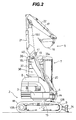
- Fig. 2 is a side view looking from the direction A in Fig. 1.
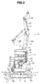
- Fig. 3 is a side view looking from the direction B in Fig. 1.
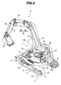
- Fig. 4 is a perspective view of the hydraulic excavator show in Fig. 1, the view being partly seen through to show the interior.
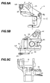
- Fig. 5 is a set of side, top plan and front views of a swing post shown in Fig. 1.
- Fig. 6 is a top plan view of a cab shown in Fig. 1.
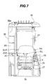
- Fig. 7 is a front view looking from the direction D in Fig. 6.
- Fig. 8 is a side view looking from the direction E in Fig. 6.
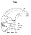
- Fig. 9 is a top plan view showing a detailed structure of an upper cover shown in Fig. 1.
- Fig. 10 is a perspective view showing a schematic structure of the upper cover shown in Fig. 1.
- Fig. 11 is an explanatory sectional view showing the positional relationship between a curved portion and a lower boom in a minimum-turn posture of a work front.
- Fig. 1 is a top plan view showing an entire structure of a swing type hydraulic excavator according to this embodiment
- Fig. 2 is a side view looking from the direction A in Fig. 1
- Fig. 3 is a side view looking from the direction B in Fig. 1
- Fig. 4 is a perspective view of the hydraulic excavator show in Fig. 1, the view being partly seen through to show the interior.
- the hydraulic excavator of this embodiment comprises an under traveling carriage 2 provided with left and right crawlers 1L, 1R serving as traveling means, a turning frame 3 turnably mounted above the under traveling carriage 2, a swing post 4 attached to the turning frame 3 rotatably in the horizontal direction about a vertical pin (not shown), a work front 5 attached to the swing post 4 rotatably in the vertical direction, a cab 7 provided on the turning frame 3 and including a seat 6, and an upper cover 8 covering most area over the turning frame 3 except the cab 7.
- the under traveling carriage 2 comprises a track frame 9 substantially in the form of H, drive wheels 10L, 10R rotatably supported in positions on the left and right sides of the track frame 9 near a rear end thereof, left and right track motors 11L, 11R driving respectively the drive wheels 10L, 10R, rotating wheels (idlers) 12L, 12R rotatably supported in positions on the left and right sides of the track frame 9 near a front end thereof and rotated by respective driving forces of the drive wheels 10 through the crawlers 1L, 1R, and a blade 14 moved up and down by a blade cylinder 13 for moving earth.
- a turning base bearing 15 is disposed at the center of the under traveling carriage 2.
- the work front 5 comprises a two-piece boom 16 made up of a lower boom 16L and an upper boom 16U, an arm 17 rotatably coupled to the upper boom 16U, a bucket 18 rotatably coupled to the arm 17, and a cross rod 19 having one end coupled to the upper boom 16U for changing an angle between the upper boom 16U and the lower boom 16L. Then, the lower boom 16L, the arm 17 and the bucket 18 are operated respectively by a boom cylinder 20, an arm cylinder 21, and a bucket cylinder 22.
- Fig. 5A and 5B are side and top plan views of the swing post 4, respectively, and Fig. 5C is a front view of the swing post looking from the direction C in Fig. 5A.
- the swing post 4 is rotatable about an axis m with respect to the turning frame 3 through the vertical pin (not shown) inserted in holes 4a, 4b. Also, the swing post 4 is coupled to a swing cylinder 23, which is provided on the turning frame 3, through a joint pin (not shown) inserted in holes 4c, 4d. Upon extension and contraction of the swing cylinder 23, the swing post 4 is entirely rotated about the axis m , causing the work front 5 to swing to the left and right.
- one end of the lower boom 16L is rotatably coupled to the swing post 4 about an axis n through a joint pin (not shown) inserted in holes 4e, 4f.
- a bottom portion of the boom cylinder 20 for operating the lower boom 16L is rotatably coupled to the swing post 4 through a joint pin (not shown) inserted in a hole 4g.
- the other end of the cross rod 19 coupled at its one end to the upper boom 16U is rotatably coupled to the swing post 4 about an axis l through a joint pin (not shown) inserted in holes 4h, 4i which is formed in a rear projecting portion 4A.
- the cross rod 19 functions as a link member for restricting a shape of the work front and changes an angle between the upper boom 16U and the lower boom 16L depending on the rotational angle of the lower boom 16L with respect to the turning frame 3.
- a turning motor 24 for turning the turning frame 3 with respect to the under traveling carriage 2 is disposed near the center of the turning frame 3.
- the cross rod 19 coupled to the upper boom 16U and the rear projecting portion 4A of the swing post 4 changes the angle between the upper boom 16U and the lower boom 16L as the lower boom 16 is raised and the work front 5 is folded.
- the boom 16 is inclined rearward to a position laterally of the cab 7 (see Fig. 2), allowing the work front 5 to turn within an area defined by the radius of turn of the turning frame 3, i.e., within the diameter close to the body width of the under traveling carriage 2.
- the position of the vertical pin (axis m ) inserted in the holes 4a, 4b of the swing post 4 is located within the radius of turn of the turning frame 3, as shown in Fig. 1.
- the above-mentioned hydraulic actuators i.e., the blade cylinder 13, the turning motor 24, the boom cylinder 20, the arm cylinder 21, the bucket cylinder 22, the swing cylinder 23, and the left and right track hydraulic motors 11, are not especially described here in detail, they are driven by any of known hydraulic drive systems (as disclosed in, e.g., JP, A, 7-189298 and JP, A, 7-26592).
- Fig. 6 is a top plan view of the cab 7
- Fig. 7 is a front view looking from the direction D in Fig. 6
- Fig. 8 is a side view looking from the direction E in Fig. 6.
- left and right travel levers 25L, 25R for driving respectively the left and right track hydraulic motors 11L, 11R of the under traveling carriage 2, a swing pedal 26 for driving the swing cylinder 23 to swing the work front 5, and a front stay 27 for protecting the operator from falling down forward.
- a side stay 28 and a side cover 29 are provided for protecting the operator from falling down to the left.
- a blade lever 30 for driving the blade cylinder 13 to move the blade 14 vertically, a switch/monitor panel 31 including various switches and monitors built therein, and a fuel lever 33 for controlling fuel supply from a fuel tank 32.
- left and right work levers 34L, 34R for driving the boom cylinder 20, the arm cylinder 21 and the bucket cylinder 22 to operate the lower boom 16L, the arm 17 and the bucket 18, respectively.
- the cab 7 comprises a roof 36 provided above the seat 6 and having a skylight 35 formed therein, a rear wall 37 provided behind the seat 6, a side wall 38 provided inward and laterally (on the right side) of the seat 6, and a slant wall 39 provided such that it extends in continuation with the side wall 38 and its end on the side near the work front 5 reaches a front edge portion 7A of the cab 7 in horizontal cross-sectional view. Additionally, a portion of the side wall 38 near its upper end is recessed toward the interior of the cab 7, thereby forming a recessed portion 38a.
- any of the rear wall 37, the side wall 38 and the slant wall 39 is made of a transparent material in its most area and disposed substantially vertically.
- the slant wall 39 is substantially flat.
- the side wall 38 is also substantially flat in its portion near the slant wall 39 except the recessed portion 38a, but is curved in its portion near the rear wall 37.
- the rear wall 37 has a curved surface.
- a hydraulic pump 43 driven by the engine 42 the fuel tank 32 for storing fuel for the engine 42
- a working oil tank 44 serving as a hydraulic fluid source of the hydraulic pump 43.
- the engine 42, the hydraulic pump 43 and the fuel tank 32 are disposed inside the upper cover 8 on the right side of the cab 7, and the working oil tank 44 serving as the hydraulic fluid source of the hydraulic pump 43 is disposed inside the upper cover 8 behind the cab 7.
- the upper cover 8 which is an important part of this embodiment will be described below with reference to Figs. 9 to 11.
- Figs. 9 and 10 are a top plan view showing a detailed structure of the upper cover 8 and a perspective view showing a schematic structure of the upper cover 8, respectively
- Fig. 11 is an explanatory sectional view showing the positional relationship between a curved portion (described later) and the lower boom 16L in the minimum-turn posture of the work front.
- the upper cover 8 has a curved portion 45 formed in its end portion on the side near the work front 5 for avoiding interference with the work front 5.
- the curved portion 45 comprises a recessed surface 45A having a center axis aligned with the axis m (see Fig.
- a first stepped portion 45B provided at a lower end of the recessed surface 45A and defining a substantially constant gap with respect to a locus drawn by the rear projecting portion 4A of the swing post 4 when the work front 5 is swung (see Fig. 11), and a second stepped portion 45C provided in an intermediate portion of the recessed surface 45A in the direction of height thereof and having a substantially horizontal surface 45C1 for assuring a foothold.
- the recessed surface 45A is configured (e.g., cone-shaped, see Fig. 11) to extend along a locus drawn by a back surface of the boom 16 when the work front 5 is swung in the minimum-turn posture, while defining a gap with respect to the locus.
- the first stepped portion 45B has a substantially vertical curved surface 45B1 (see Fig. 11) formed in continuation with the lower end of the recessed surface 45A and defining a substantially constant gap with respect to the locus drawn by the rear projecting portion 4A of the swing post 4 when the work front 5 is swung, and a substantially horizontal surface 45B2 (see Fig. 11) formed in continuation with the curved surface 45B1 on the side near the work front 5 and defining a substantially constant gap with respect to a locus drawn by a lower end of the rear projecting portion 4A of the swing post 4 when the work front 5 is swung.
- the substantially vertical curved surface 45B1 has a shape having a center axis aligned with the axis m of the vertical pin of the swing post 4.
- the substantially horizontal surface 45B2 is configured such that its free edge is in the arcuate form having a center axis aligned with the axis m of the vertical pin and its portions near both circumferential ends 45B2l, 45B2r have lower height than its portion near the circumferential middle 45B2m.
- the upper cover 8 further includes an oil tank cover 46 for covering the working oil tank 44, an inspection cover 47 opened and closed in maintenance, an oil supply hole 48 through which the fuel is replenished to the fuel tank 32.
- This embodiment constructed as described above operates as follows.
- the curved portion 45 is formed in the end portion of the upper cover 8 on the side near the work front 5, and the recessed surface 45A, which is configured to have the center axis aligned with the axis m of the vertical pin and extend along the above locus while defining a gap with respect to the above locus, is formed in the curved portion 45.
- the boom 16 is prevented from interfering with the upper cover 8 even when the boom 16 is inclined rearward to a large extent in the minimum-turn posture.
- the structure also has an additional advantage that since earth and sand falling from the bucket 18 in a slight turn, for example, are more easily slipped down along the recessed surface 45A, a build-up of earth and sand on the upper cover 8 is suppressed.
- the first stepped portion 45B defining the substantially constant gap with respect to the locus drawn by the rear projecting portion 4A of the swing post 4 when the work front 5 is swung, is provided. Therefore, even when the work front 5 is swung in the minimum-turn posture, a substantially constant gap is always maintained between the first stepped portion 45B and the rear projecting portion 4A, whereby interference between these two portions is prevented.
- the above two interference preventing functions permit the boom 16 to be inclined rearward to a large extent in the minimum-turn posture.
- the work front 5 can be turned within the radius of turn of the turning frame 3, i.e., within the diameter close to the body width of the under traveling carriage 2.
- the substantially vertical curved surface 45B1 and the substantially horizontal surface 45B2 are formed in the first stepped portion 45B so that earth and sand sliding down over the recessed surface 45A are once accumulated on the substantially horizontal surface 45B1, and the earth and sand are then scraped out in the circumferential direction for discharge upon the rotating movement of the swing post 4.
- the spaces around the vertical pin and the attachment end of the lower boom 16L can be thereby protected against jamming of earth and sand.
- the substantially horizontal surface 45B2 has lower height in its portions near both the circumferential ends 45B2l, 45B2r than its portion near the circumferential middle 45B2m, the earth and sand once stored on the first stepped portion 45B can be guided toward both the circumferential ends 45B2l, 45B2r. As a result, the spaces around the vertical pin and the attachment end of the lower boom 16L can be more surely protected.
- the volume defined by the upper cover 8 is reduced minimally, i.e., just in amount corresponding to the provision of the recessed surface 45A, the first stepped portion 45B and the second stepped portion 45C. Therefore, a space sufficient for installing the necessary equipments can be ensured inside the upper cover 8.
- the present invention is not limited to such a construction.
- the present invention is also applicable to any of a hydraulic excavator wherein the turning frame 3 is turnable within a diameter somewhat larger than the under traveling carriage 2, a hydraulic excavator wherein the turning frame 3 is turnable within the body width of the under traveling carriage 2 contrary to the above case, a hydraulic excavator wherein the work front 5 is turnable within an area slightly larger than (but close to) the radius of turn of the turning frame 3, and a hydraulic excavator wherein the work front 5 is turnable within an area somewhat larger than the radius of turn of the turning frame 3.
- any of these cases can also provide the advantages specific to the present invention, i.e., that the radius of turn of the work front 5 in the minimum-turn posture can be reduced while minimizing a reduction in volume defined by the upper cover 8.
- the present invention is more effective in hydraulic excavators wherein the turning frame 3 is turnable within a smaller diameter and hydraulic excavators wherein the work front 5 is turnable within a smaller diameter in the minimum-turn posture, because the space inside the upper cover 8 is more restricted in those hydraulic excavators.
- the above embodiment has been described, by way of example, in connection with a hydraulic excavator having the boom 16 of so-called two-piece boom type.
- the present invention is not limited to the above embodiment, and may be applied to a hydraulic excavator having a boom of so-called mono-boom type as well. In this case, similar advantages as with the above embodiment can also be obtained.
- the work front and the upper cover can be prevented from interfering with each other due to the presence of the recessed surface provided in the curved portion. Consequently, the radius of turn of the work front in the minimum-turn posture can be reduced while minimizing a reduction in volume defined by the upper cover.
Landscapes
- Engineering & Computer Science (AREA)
- Mechanical Engineering (AREA)
- Mining & Mineral Resources (AREA)
- Civil Engineering (AREA)
- General Engineering & Computer Science (AREA)
- Structural Engineering (AREA)
- Component Parts Of Construction Machinery (AREA)
- Shovels (AREA)
- Body Structure For Vehicles (AREA)
Applications Claiming Priority (3)
| Application Number | Priority Date | Filing Date | Title |
|---|---|---|---|
| JP14104/96 | 1996-01-30 | ||
| JP1410496 | 1996-01-30 | ||
| PCT/JP1997/000182 WO1997028316A1 (en) | 1996-01-30 | 1997-01-28 | Swing type hydraulic excavator |
Publications (2)
| Publication Number | Publication Date |
|---|---|
| EP0818583A1 true EP0818583A1 (de) | 1998-01-14 |
| EP0818583A4 EP0818583A4 (de) | 2001-04-04 |
Family
ID=11851820
Family Applications (1)
| Application Number | Title | Priority Date | Filing Date |
|---|---|---|---|
| EP97900788A Withdrawn EP0818583A4 (de) | 1996-01-30 | 1997-01-28 | Schwenkbarer hydraulischer bagger |
Country Status (5)
| Country | Link |
|---|---|
| US (1) | US5975833A (de) |
| EP (1) | EP0818583A4 (de) |
| KR (1) | KR100236117B1 (de) |
| CN (1) | CN1075852C (de) |
| WO (1) | WO1997028316A1 (de) |
Cited By (2)
| Publication number | Priority date | Publication date | Assignee | Title |
|---|---|---|---|---|
| GB2344809A (en) * | 1998-12-16 | 2000-06-21 | Bamford Excavators Ltd | Earth moving apparatus |
| EP2500474A4 (de) * | 2009-11-11 | 2017-02-15 | Kobelco Construction Machinery Co. Ltd. | Baumaschine mit einem gerüst zur durchführung von wartungsarbeiten |
Families Citing this family (19)
| Publication number | Priority date | Publication date | Assignee | Title |
|---|---|---|---|---|
| US6058903A (en) * | 1997-12-18 | 2000-05-09 | Caterpillar Inc. | Engine enclosure |
| US6886277B2 (en) * | 2002-02-15 | 2005-05-03 | Kubota Corporation | Small swivel type working vehicle |
| US6772544B2 (en) * | 2002-03-28 | 2004-08-10 | Kubota Corporation | Wheeled work vehicle |
| JP4128085B2 (ja) * | 2002-05-22 | 2008-07-30 | 株式会社小松製作所 | 液体タンク |
| JP2004036169A (ja) * | 2002-07-02 | 2004-02-05 | Komatsu Ltd | 作業車両 |
| US7374208B2 (en) * | 2003-03-18 | 2008-05-20 | Kobelco Construction Machinery Co., Ltd. | Working machine |
| US7290829B2 (en) * | 2004-06-29 | 2007-11-06 | Kubota Corporation | Working vehicle with a cab |
| US8024875B2 (en) * | 2005-12-02 | 2011-09-27 | Clark Equipment Company | Compact excavator implement interface |
| ES2302617B1 (es) * | 2006-05-24 | 2009-05-21 | Cavosa, Obras Y Proyectos S.A. | Maquina retroexcavadora. |
| CN101307610B (zh) * | 2008-07-16 | 2013-04-03 | 李明家 | 履带式装载机 |
| KR101811771B1 (ko) * | 2011-05-12 | 2017-12-22 | 히다치 겡키 가부시키 가이샤 | 건설기계 |
| CN102251771A (zh) * | 2011-05-27 | 2011-11-23 | 三一重型装备有限公司 | 一种掘钻一体机 |
| USD686642S1 (en) * | 2012-05-10 | 2013-07-23 | Hitachi Construction Machinery Co., Ltd. | Swing post for a construction machine |
| EP2677087B1 (de) | 2012-06-21 | 2014-12-31 | Caterpillar Work Tools B. V. | Querverbinderanordnung für ein hängendes Arbeitswerkzeug |
| NL2012278C2 (nl) * | 2014-02-17 | 2015-08-25 | Hudson Bay Holding B V | Gelede werkarm en mobiele inrichting met verbeterde montage van stuurorgaan. |
| JP6633464B2 (ja) * | 2016-07-06 | 2020-01-22 | 日立建機株式会社 | 作業機械 |
| WO2019064517A1 (ja) * | 2017-09-29 | 2019-04-04 | 株式会社日立建機ティエラ | 建設機械 |
| JP7283910B2 (ja) * | 2019-02-01 | 2023-05-30 | 株式会社小松製作所 | 建設機械の制御システム、建設機械、及び建設機械の制御方法 |
| NL2024981B1 (en) * | 2020-02-24 | 2021-10-14 | Hudson I P B V | Electric drive of mobile apparatus |
Family Cites Families (11)
| Publication number | Priority date | Publication date | Assignee | Title |
|---|---|---|---|---|
| CA1195661A (en) * | 1982-07-22 | 1985-10-22 | Yokichi Nagasawa | Earth-working machine |
| JPS6171643A (ja) * | 1984-09-17 | 1986-04-12 | Toshiba Corp | 超音波ワイヤボンデイング方法 |
| JPS6171643U (de) * | 1984-10-15 | 1986-05-15 | ||
| JPS62202130A (ja) * | 1986-02-28 | 1987-09-05 | Kubota Ltd | バックホウ |
| JPH0284857A (ja) * | 1988-09-20 | 1990-03-26 | Nec Corp | 着呼通知方式 |
| JPH0284857U (de) * | 1988-12-16 | 1990-07-02 | ||
| JPH03255241A (ja) * | 1990-03-02 | 1991-11-14 | Yanmar Diesel Engine Co Ltd | 油圧コントロールバルブ台の防振支持機構 |
| JP2895284B2 (ja) * | 1991-10-31 | 1999-05-24 | ヤンマーディーゼル株式会社 | 旋回作業車 |
| JP3197649B2 (ja) * | 1993-01-27 | 2001-08-13 | セイレイ工業株式会社 | 掘削作業機 |
| JP2631942B2 (ja) * | 1993-06-25 | 1997-07-16 | 小松ゼノア株式会社 | 超小旋回パワショベル |
| JP3304186B2 (ja) * | 1994-03-07 | 2002-07-22 | 日立建機株式会社 | スイング方式の掘削機 |
-
1997
- 1997-01-28 EP EP97900788A patent/EP0818583A4/de not_active Withdrawn
- 1997-01-28 KR KR1019970706673A patent/KR100236117B1/ko not_active Expired - Fee Related
- 1997-01-28 CN CN97190054A patent/CN1075852C/zh not_active Expired - Fee Related
- 1997-01-28 US US08/913,993 patent/US5975833A/en not_active Expired - Fee Related
- 1997-01-28 WO PCT/JP1997/000182 patent/WO1997028316A1/ja not_active Ceased
Cited By (3)
| Publication number | Priority date | Publication date | Assignee | Title |
|---|---|---|---|---|
| GB2344809A (en) * | 1998-12-16 | 2000-06-21 | Bamford Excavators Ltd | Earth moving apparatus |
| GB2344809B (en) * | 1998-12-16 | 2002-10-02 | Bamford Excavators Ltd | Earth moving apparatus |
| EP2500474A4 (de) * | 2009-11-11 | 2017-02-15 | Kobelco Construction Machinery Co. Ltd. | Baumaschine mit einem gerüst zur durchführung von wartungsarbeiten |
Also Published As
| Publication number | Publication date |
|---|---|
| EP0818583A4 (de) | 2001-04-04 |
| WO1997028316A1 (en) | 1997-08-07 |
| KR100236117B1 (ko) | 1999-12-15 |
| KR19980703269A (ko) | 1998-10-15 |
| CN1178566A (zh) | 1998-04-08 |
| US5975833A (en) | 1999-11-02 |
| CN1075852C (zh) | 2001-12-05 |
Similar Documents
| Publication | Publication Date | Title |
|---|---|---|
| US5975833A (en) | Swing type hydraulic excavator | |
| JPH076217B2 (ja) | 全旋回式作業機 | |
| WO2007073457A1 (en) | Rotatable cab with toe guard | |
| CN110226009B (zh) | 液压挖掘机 | |
| JP4044314B2 (ja) | 建設機械 | |
| WO2011148945A1 (ja) | 建設機械 | |
| JP3540541B2 (ja) | スイング式油圧ショベル | |
| JP3489951B2 (ja) | スイング式油圧ショベル | |
| JP3532790B2 (ja) | 建設機械及びそれに用いるコンソール装置 | |
| JP3589595B2 (ja) | 旋回作業機 | |
| JP2930930B2 (ja) | 旋回作業車 | |
| JP2895483B2 (ja) | 旋回作業車 | |
| CN219808429U (zh) | 用于箱体的安装构件及包含其的挖掘机 | |
| JP4742195B2 (ja) | バックホー | |
| JP3197649B2 (ja) | 掘削作業機 | |
| EP4534763A1 (de) | Arbeitsmaschine | |
| JP2954913B2 (ja) | 旋回式掘削作業車 | |
| KR102682911B1 (ko) | 굴삭기 | |
| JP2024057331A (ja) | ペダル装置およびこれを備えた作業機械 | |
| JP2024049069A (ja) | 建設機械 | |
| JP3810143B2 (ja) | 油圧ショベル | |
| JP2812438B2 (ja) | 旋回作業車 | |
| JP2024142157A (ja) | 建設機械 | |
| JP2022081167A (ja) | 建設機械 | |
| JP2000257117A (ja) | 運転室付き建設機械 |
Legal Events
| Date | Code | Title | Description |
|---|---|---|---|
| PUAI | Public reference made under article 153(3) epc to a published international application that has entered the european phase |
Free format text: ORIGINAL CODE: 0009012 |
|
| 17P | Request for examination filed |
Effective date: 19971020 |
|
| AK | Designated contracting states |
Kind code of ref document: A1 Designated state(s): DE FR GB IT SE |
|
| A4 | Supplementary search report drawn up and despatched |
Effective date: 20010216 |
|
| AK | Designated contracting states |
Kind code of ref document: A4 Designated state(s): DE FR GB IT SE |
|
| RIC1 | Information provided on ipc code assigned before grant |
Free format text: 7E 02F 3/36 A, 7E 02F 9/24 B, 7E 02F 9/08 B, 7E 02F 3/30 B, 7E 02F 3/38 B |
|
| STAA | Information on the status of an ep patent application or granted ep patent |
Free format text: STATUS: THE APPLICATION IS DEEMED TO BE WITHDRAWN |
|
| 18D | Application deemed to be withdrawn |
Effective date: 20030801 |