EP0810776B1 - Bildkombinationsgerät und -verfahren - Google Patents
Bildkombinationsgerät und -verfahren Download PDFInfo
- Publication number
- EP0810776B1 EP0810776B1 EP97303567A EP97303567A EP0810776B1 EP 0810776 B1 EP0810776 B1 EP 0810776B1 EP 97303567 A EP97303567 A EP 97303567A EP 97303567 A EP97303567 A EP 97303567A EP 0810776 B1 EP0810776 B1 EP 0810776B1
- Authority
- EP
- European Patent Office
- Prior art keywords
- image
- tone
- images
- corresponding points
- correction
- Prior art date
- Legal status (The legal status is an assumption and is not a legal conclusion. Google has not performed a legal analysis and makes no representation as to the accuracy of the status listed.)
- Expired - Lifetime
Links
Images








Classifications
-
- H—ELECTRICITY
- H04—ELECTRIC COMMUNICATION TECHNIQUE
- H04N—PICTORIAL COMMUNICATION, e.g. TELEVISION
- H04N1/00—Scanning, transmission or reproduction of documents or the like, e.g. facsimile transmission; Details thereof
- H04N1/387—Composing, repositioning or otherwise geometrically modifying originals
- H04N1/3876—Recombination of partial images to recreate the original image
-
- H—ELECTRICITY
- H04—ELECTRIC COMMUNICATION TECHNIQUE
- H04N—PICTORIAL COMMUNICATION, e.g. TELEVISION
- H04N1/00—Scanning, transmission or reproduction of documents or the like, e.g. facsimile transmission; Details thereof
- H04N1/40—Picture signal circuits
- H04N1/407—Control or modification of tonal gradation or of extreme levels, e.g. background level
- H04N1/4072—Control or modification of tonal gradation or of extreme levels, e.g. background level dependent on the contents of the original
-
- H—ELECTRICITY
- H04—ELECTRIC COMMUNICATION TECHNIQUE
- H04N—PICTORIAL COMMUNICATION, e.g. TELEVISION
- H04N23/00—Cameras or camera modules comprising electronic image sensors; Control thereof
- H04N23/60—Control of cameras or camera modules
- H04N23/698—Control of cameras or camera modules for achieving an enlarged field of view, e.g. panoramic image capture
Definitions
- the present invention relates to an apparatus and a method for combining images, and more particularly, to an image combining apparatus and method thereof for combining a plurality of images partially including an overlapping region having the same image, to generate one panoramic image having a wide angle of view.
- an image of a subject shown in Fig. 1 is picked up by an electronic still camera or the like, taking two frames (frame f1 and frame f2) of photographs. Since the subject picked up by the frame f1 has a dark atmosphere as a whole, the camera corrects an exposure amount at the time of image pick-up such that the dark portion would be lighter. As a result, an image shown in Fig. 2A is obtained. Since the subject picked up by the frame f2 has a light atmosphere as a whole, the camera corrects an exposure amount at the time of image pick-up such that the light portion would be darker. As a result, an image shown in Fig. 2B is obtained. Accordingly, even if the two inputted images (images in Fig. 1A and 1B) are combined precisely, the combined image shown in Fig. 3 would have a conspicuous line due to the difference in lightness.
- the present invention has been made in consideration of the above situation, and has as a concern to provide an image combining apparatus and method capable of combining images in a manner such that the boundary of the images is inconspicuous even in a case where exposure conditions are different for each inputted image.
- JP-A-7-115534 describes an image reading apparatus capable of combining images to make an oversized image.
- the apparatus described in this document first corrects data in an overlapped region and then the data is smoothed or binarised in dependence on whether the overlap region is detected as being characters or a photo image.
- GB-A-2130838 describes a method and apparatus for forming a combined image signal wherein image signals representative of one of the neighbouring images are modified with respect to image density within a predetermined distance from an interface between the neighbouring images so that the image density gradually varies from the predetermined distance towards the interface at a desired rate of variation.
- an image combining apparatus as set out in claim 1.
- the invention provides an image combining method as set out in claim 13.
- An embodiment of the present invention provides an image combining apparatus and method which can generate a combined image whose boundary of the images is inconspicuous, by discriminating and identifying an overlapping region having the same image in two inputted images, and correcting tones of either or both of the inputted images in accordance with difference in tone density between the two inputted images.
- An embodiment of the present invention provides an image combining apparatus and method which can generate a combined image whose boundary of the images is inconspicuous, by performing tone correction particularly in the neighbour of the boundary.
- An embodiment of the present invention provides an image combining apparatus and method which can generate a combined image whose boundary of the images is inconspicuous, by performing tone correction on pixels in the neighbor of the boundary in the overlapping region, in accordance with how far the pixel of interest is from the boundary.
- An embodiment of the present invention provides an image combining apparatus and method which can generate a combined image whose boundary of the images is inconspicuous, by removing erroneously recognized corresponding points from a set of corresponding points which have been detected to identify the overlapping region of the images, and by determining parameters of tone correction on the basis of the set of corresponding points from which the erroneous corresponding points are removed, thereby increasing precision of tone correction.
- Fig. 4 shows the arrangement of an image combining apparatus 1000 according to the first embodiment of the present invention.
- the combining apparatus 1000 may be a single apparatus, or may be built in a camera or the like.
- the apparatus serves to input two input images a and b, and to output a combined image c.
- input images a and b are picked up by an electronic still camera or a video camera or the like in a manner such that both images partially include an overlapping region having the same image. Even if the input images a and b are picked up with different exposure conditions such as those shown in Figs. 2A and 2B (e.g. one image picked up in a dark condition, and the other in a light condition), the combine apparatus 1000 outputs a combined image c whose boundary of the images is inconspicuous.
- the combine apparatus 1000 includes a corresponding-point-extracting unit 1, parameter estimating unit 2, correction-coefficient-determining unit 3, two tone converting units 4 and 5, and image combining unit 6.
- the corresponding-point-extracting unit 1 extracts corresponding points from the two input images a and b.
- corresponding points are each of the respective points in two images including an identical subject, which are picked up in separate image pick-up operation by the same light source.
- the corresponding points are outputted in the form of vectors.
- the corresponding-point-extracting unit 1 identifies an overlapping region of images a and b .
- a parameter estimating unit 2 estimates parameters used for image conversion for the purpose of combining the two images, on the basis of the corresponding-points vectors extracted by the extracting unit 1.
- a correction-coefficient-determining unit 3 determines coefficients used for tone correction performed on each of the input images a and b .
- the correction coefficients are determined on the basis of image data in the overlapping region of the input images a and b .
- Tone converting units 4 and 5 respectively perform tone correction on the input images a and b such that lightness and tonality of every colors are equal in the overlapping region of the two images.
- An image combining unit 6 converts the input images a and b, whose lightness has been corrected, utilizing the conversion parameters and combines the two images into a single image.
- a control unit 7 controls the entire image combining apparatus.
- the corresponding-point-extracting unit 1 extracts corresponding points from the input images a and b to identify an overlapping region.
- the process algorithm performed by the corresponding-point-extracting unit 1 is shown in Fig. 5.
- the algorithm shown in Fig. 5 is executed to perform template matching and extract corresponding points (i.e. overlapping region).
- step S1 the corresponding-point-extracting unit 1 determines a region which includes a template for performing template matching (hereinafter referred to as a template region). Since the frames of the input images a and b are arbitrarily set, the overlapping region cannot be determined in advance. Thus, the extracting unit 1 sets a predetermined region as a template region.
- the predetermined region can be determined in various ways.
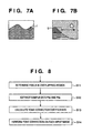
- a predetermined region T is set as shown in Fig. 6A.
- the region T is located in the right portion of the image a .
- the horizontal length of the region T is 30% of the horizontal length of the image a
- a vertical length of the region T is 80% of the vertical length of the image a . Note that the region T is located in the center of the vertical length of the image a , with the right end thereof adjoining to the right end of the image a .
- the template region T is set as shown in Fig. 6B. More specifically, the region T is located at the lower portion of the image a .
- the vertical length of the region T is 30% of the vertical length of the image a
- the horizontal length of the region T is 80% of the horizontal length of the image a .
- the region T is located in the center of the horizontal length of the image a , with the lower end adjoining to the lower end of the image a .
- a single searching template is indicated by "t" in Fig. 6A.
- Steps S2 to S4 which will be described below are performed with respect to the region T extracted in step S1.
- step S2 the corresponding-point-extracting unit 1 determines a searching objective area S in the input image b, and within the area S, sets a searched area s which corresponds to the searching template t designated in the image a .
- the searching objective area S is set in the similar manner to the setting of the region T. That is, the searching objective area S as well as the searching template t are determined as shown in Figs.
- the template t which is a searched area s is set to have a size of 10 % in the vertical direction and less than 50 % (preferably, 40 %) in the horizontal direction, of the image a .
- the area S shown in Fig. 7B is the searching objective area S set in correspondence with the template t shown in Fig. 7A.
- the extracting unit 1 identifies a corresponding point in step S3. More specifically, the extracting unit 1 parallelly moves the template t set in the image a within the searching objective area S set in the area b, i.e. the area s is moved within the area S.
- the extracting unit 1 then calculates a summation of absolute values of difference between all the image data included in the searching template t and all the image data included in the area s.
- the extracting unit 1 determines a position in the image b having the minimum summation ⁇ D of the absolute values of the differences, as a corresponding point of the template t.
- step S4 the corresponding-point-extracting unit 1 determines reliability of the result of the corresponding points detected in step S3.
- the determination of reliability is made on the basis of the minimum value ⁇ D 1 min and the second minimum value ⁇ D 2 min of the summation ⁇ D of the absolute values of the differences. That is, assuming that Th 1 and Th 2 are the respective predetermined threshold values, the detected corresponding point is determined to be reliable when the following equations are satisfied: ⁇ D 1 min ⁇ Th 1 ⁇ D 2 min - ⁇ D 1 min ⁇ Th 2 Then the corresponding-point-extracting unit 1 stores coordinates of the corresponding points for the images a and b respectively in a memory (not shown).
- the extracting unit 1 may calculate a correlation and determine a position having the largest correlation value as the corresponding point.
- the corresponding position may be determined by a user. For instance, a user may designate an identical point in both images with a cursor or the like to be extracted, by referring to the two images a and b displayed on a display.
- the overlapping region of the images a and b are determined by repeatedly performing the control steps described in Fig. 5.
- the parameter estimating unit 2 estimates parameters for coordinates conversion on the basis of the extracted corresponding points from the overlapping region.
- coordinates conversion is the operation to coincide the overlapping region of the image a with the overlapping region of the image b.
- Affin transformation is employed.
- an arbitrary point (x a , y a ) in the image a corresponds to the point (x b , y b ) in the image b defined by the following equation (3):
- the parameter estimating unit 2 estimates the parameters A, B, C and D employing the least squares method. In order to estimate the parameters using the least squares method, at least two pairs of corresponding points are necessary.
- the subsequent processing will not be performed; instead, for instance, a message or the like is outputted to a CRT and the processing ends.
- the parameters obtained in the above manner are used when an overlapping region is estimated.
- the tone converting units 4 and 5 perform tone conversion on the inputted images a and b respectively so that the lightness and tonality of colors (R, G and B) are equal in the overlapping region of the two images.
- the correction-coefficient-determining unit 3 determines correction coefficients for the tone conversion processing.
- tone conversion on lightness components is made in the embodiment.
- tone correction on each color R, G and B
- a tone conversion using individual tone correction function is made on each of R, G and B images.
- Fig. 8 shows the process algorithm performed by the correction-coefficient-determining unit 3 and the tone converting units 4 and 5.
- the correction-coefficient-determining unit 3 inputs parameters A, B, C and D estimated by the estimating unit 2 for coordinates conversion, and the images a and b.
- the tone converting units 4 and 5 respectively input the images a and b.
- step S11 of Fig. 8 the correction-coefficient-determining unit 3 determines whether or not each pixel of the input images a and b is within the overlapping region. For determination, coordinates values of each pixel in the input images are subjected to Affin transformation according to the equation (3), utilizing the parameters A, B, C and D. Then determination is made as to whether or not the coordinates values on which Affin transformation has been performed are within the area determined to be the overlapping region of the image b.
- step S12 of Fig. 8 the correction-coefficient-determining unit 3 takes samples of image data for all or a predetermined number of pixels which are determined to be included in the overlapping region.
- N number of sample pixels are obtained.
- P b (x', y') represents a pixels value at (x, y) coordinate position which corresponds to the location (x', y') that has been subjected to the Affin transformation.
- S of the equation (5) represents a function which performs tone conversion processing in pixels which is accompanied with the above coordinate transformation. The tone conversion processing will be described in detail later.
- correction-coefficient-determining unit 3 may perform the sampling of pixel values pixel by pixel, or for every arbitrary number of pixels. Moreover, the correction-coefficient-determining unit 3 may utilize, as sample data, an average value of the neighboring pixel values based on the coordinates of the corresponding points obtained by utilizing the parameters.
- the correction-coefficient-determining unit 3 then obtains tone correction coefficients in step S13 of Fig. 8 on the basis of the sample data P a (k) and P b (k).
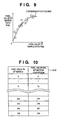
- Fig. 9 shows the brief method of calculating tone correction coefficients.
- the abscissa indicates a density value of the sample pixel data P b (k) of the image b; and the ordinate, a density value of the sample pixel data P a (k) of the image a .
- the correction-coefficient-determining unit 3 generates a conversion function (function f900 in Fig. 9) on the basis of the above sample data, to coincide the pixel density value of one image (e.g. image a ) to the pixel density value of the other image (e.g. image b).
- the tone converting units 4 and 5 convert pixel values of each of the images a and b in accordance with the tone correction coefficients T b1 , T b2 and T b3 in step S14 of Fig. 8.
- the operation performed by the tone converting unit 5 will be described.
- the tone converting unit 5 converts tones of the image b into tones of the image a .
- the tone converting unit 5 generates a table for converting the tones of the image b to the tones of the image a on the basis of the tone correction coefficients T b1 , T b2 and T b3 .
- T b1 , T b2 and T b3 When the dynamic range of an image is 8 bits, pixel values 0 to 255 of the image b have the values f(0) to f(255) in the space of the image a , according to the quadratic function f(P b ) in equation (6). Examples of f(0) to f(255) in a conversion table 910 are shown in Fig. 10.
- tone conversion by generating a conversion function commonly utilized by R, G and B. Tone conversion functions for respective colors may be provided so that color matching may be improved.
- quadratic function is utilized as a conversion function in the first embodiment, it is possible to utilize another form of function. Needless to say, it is also possible to perform tone conversion by utilizing a non-linear table.
- Image combining unit 6 generates a single combined image, on the basis of the input images and the images on which the tone correction has been respectively performed by the tone converting unit 4 and 5.
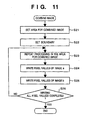
- the image combining unit 6 generates a combined image c in accordance with an algorithm shown in Fig. 11.
- step S21 the image combining unit 6 sets an image area for the combined image c.
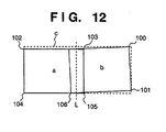
- the area indicated by broken lines in Fig. 12 denotes the area for the combined image which has been set on the basis of a coordinates system of the input image a . Since the description of the first embodiment bases upon the coordinates of the input image a , for the purpose of a simple explanation, the upper side and the lower side of the image a are assumed to be parallel to coordinates axis X.
- the image combining unit 6 first coincides the left, end of the combined image c with the left end of the image a .
- the image combining unit 6 converts a position of the pixel (100) at the upper right end of the image b and a position of the pixel (101) at the lower right end of the image b respectively to positions in the coordinates system of the image a .
- the image combining unit 6 coincides the right end of the combined image c with a position having a larger coordinates value between the converted two positions.
- the image combining unit 6 coincides the right end of the combined image c with the lower right end 101.
- the image combining unit employs the inverse transformation of Affin transformation shown in Fig. (8).
- A' A /(A 2 + B 2 )
- B' -B /(A 2 + B 2 )
- C' (-A•C + B • D)/(A 2 +B 2 )
- D' (-B • C - A • D)/(A 2 + B 2 )
- A', B', C' and D' are parameters of the inverse transformation.
- the upper end of the combined image c is determined in the following manner. More specifically, the position of the pixel (100) at the upper right end of the image b and the position of the pixel (103) at the upper left end are converted respectively to positions in the coordinates system of the image a .
- the image combining unit 6 coincides the upper end of the combined image c with a position having the smallest coordinates value among the two converted positions, and the position of the pixel (102) at the upper left end of the image a.
- the image combining unit 6 coincides the lower end of the combined image c with a position having a larger coordinates value between the position of the pixel (101) at the lower right end and the position of the pixel (105) at the lower left end of the image b.
- the combined image area c shown in Fig. 12 is determined in the above-described manner.
- step S22 in Fig. 11 the image combining unit 6 sets a boundary of the images so that the boundary is the center of the overlapping region. Since the images a and b are arranged side by side in the first embodiment, the boundary L which has been set in the center is indicated by broken lines L in Fig. 12. To explain more in detail, the boundary L is set parallel to vertical coordinates axis Y.
- the boundary L is set so that the two images are combined at a barycenter between the coordinates of the pixel 106 located at the lower right end of the image a and a smaller coordinates value of the two pixels 103 or 105, respectively located at the upper left end and lower left end of the image b, which have been converted respectively to pixel positions in the coordinates system of image a .
- step S23 the image combining unit 6 repeatedly performs the processing in steps S24 and S25 on the area for the combined image c set in step S21.
- the present invention has an object to generate a combined image whose density difference at the boundary of the images is inconspicuous. This object is partially attained by the tone correction in step S14 in Fig. 8.
- the tone conversion performed in step S14 is performed independently for each of the input images a and b, therefore does not always minimize the density difference near the boundary of the images in the overlapping region.
- the processing performed in steps S24 and S25 further smoothes the density difference near the boundary of the images in the overlapping region.
- a tone conversion area 150 having a predetermined width 2W is set in steps S24 and S25 of Fig. 11, with the boundary L of the images as its center.
- the tone conversion area 150 is a rectangular area having a width W respectively to the left and right of the boundary L.
- step S24 the image combining unit 6 writes pixel values of the pixels of the image a in the corresponding area of the combined image area c. With respect to those pixels included in an area 140a of the image a shown in Fig. 13 but not included in the tone conversion area 150, the image combining unit 6 writes the pixel values of the original image a . With respect to a pixel P a in the image a included in the tone conversion area 150, the image combining unit 6 determines a tone conversion value P' a in accordance with how far (dx a ) the pixel P a is from the boundary L. The tone conversion value P' a is determined by the following equation, utilizing a function f defined in the above-described conversion table (Fig. 10) stored in the tone converting unit 4.
- the tone conversion value P' a is obtained by adding a correction term P a ⁇ dx a / W - f(P a ) ⁇ dx a / W corresponding to a distance dx a is added to the value f(P a ) which has been corrected in accordance with a function f in the conversion table.
- step S25 the image combining unit 6 similarly writes pixel values with respect to the area of image b. That is, with respect to those pixels included in an area 140b of the image b shown in Fig. 13 but not included in the tone conversion area 150, the image combining unit 6 writes the pixel value of the original image b. With respect to a pixel P b in the image b included in the tone conversion area 150, the image combining unit 6 determines a tone conversion value P' b in accordance with how far (dx b ) the pixel P b is from the boundary L. The tone conversion value P' b is determined by the following equation, utilizing a function f' defined in the conversion table stored in the tone converting unit 5.
- Fig. 14 shows the combined image c obtained in the above-described manner.
- a dummy area 160 indicated by hatching in Fig. 14 is a region where pixels of neither the image a nor image b are written.
- a dummy pixel e.g. white pixel or the like.
- Fig. 15 shows the variation of pixel values at an arbitrary line H in the combined image c shown in Fig. 14.
- the drop 170 of the pixel value P a represents a dark subject; and the rise 171 of the pixel value P b , a light subject.
- the pixel values located in the left side of the boundary L are the pixel values of the original image a .
- equation (10) the pixel values located in the left side of the boundary L are not converted even though the pixels are within the tone conversion area 150.
- tone conversion performed on each pixel would be different depending upon whether the pixel is within the tone conversion area 150R (width W). More specifically, with respect to a pixel value 133 included in the tone conversion area 150R, the pixel value is converted by the equation (11) such that the value gradually changes from the pixel value 131 of the original image b to the pixel value 132 converted in accordance with the correction table (function f') stored in the tone converting unit 5.
- the image combining unit 6 performs writing of pixel values for the area of image a separately from the area of the image b, dividing the combined image area by the boundary L.
- a plurality of areas may be set in the overlapping region of each image (150L and 150R), and weights may be added to the pixel values of each image in each of the plurality of areas to generate pixel values of a combined image.
- the combined image c generated by the foregoing processing is outputted to a printer or the like.
- An image combining apparatus has the same arrangement as that of the first embodiment shown in Fig. 4. However the functions and operation of the correction-coefficient-determining unit 3 and the image combining unit 6 are different from those of the first embodiment. The operation will be described hereinafter.
- the correction-coefficient-determining unit 3 determines pixel values included in the tone conversion area 150 on the basis of pixel values in the overlapping region of the input images a and b. The technique of determining thereof will be described with reference to Fig. 16.
- the correction-coefficient-determining unit 3 generates sample data P a (k) and P b (k) of corresponding points on the basis of the pixel values (see Fig. 16) included in the overlapping region of the image a and b.
- the correction-coefficient-determining unit 3 calculates an average value dP avg of difference dP in each pair of corresponding points, and supplies the average value dP avg to the image combining unit 6.
- the reference letter Y denotes a lateral width of the image a.
- the image b has the same lateral width Y.
- dP avg in equation (12) denotes the difference in tones between each pair of corresponding points in the overlapping region of the images, having a maximum value 255 and a minimum value 0.
- equation (12) when the difference of the tone levels is large, the width 2W in the tone conversion area becomes large; and when the difference of the tone levels is small, the width 2W becomes small.
- the foregoing description explains the technique of determining the tone conversion area according to the first modified embodiment, more specifically, the method of determining a width of the tone conversion area in correspondence with difference in tone levels, in a case where tones of the image a are different from tones of the image b in the overlapping region.
- a combined image is generated in the same manner as that of the first embodiment.
- the tone conversion area can be suitably set in correspondence with the difference in tone levels in the overlapping region of the images, it is possible to perform smooth tone correction which is appropriate for an inputted image.
- the image combining apparatus extracts sample data on the basis of pixel values in the overlapping region of input images a and b. This operation is identical to that of the first embodiment.
- the correlation between a pair of pixel values P a and P b which are extracted as sample data is determined in accordance with the method shown in Fig. 9.
- the conversion function f900 (Fig. 9) is generated to coincide tones of the image b with tones of the image a on the basis of the relationship of each sample data by utilizing the least squares method. Accordingly, in the first embodiment, conversion of pixel values performed for tone correction is executed only on the image b. In the second modified embodiment, tone correction is executed on pixel values P a and P b of each image.
- the correction-coefficient-determining unit 3 generates a conversion function f as similar to the technique described in the first embodiment with reference to Fig. 9, and provides the tone converting units 4 and 5 with tone correction coefficients (T b1 , T b2 and T b3 ) which prescribe the function f.
- the conversion function f serves to coincide pixel values of image b with pixel values of image a , as similar to the first embodiment.
- the tone converting unit 5 for converting the input image b performs tone conversion utilizing the conversion function f on the basis of the pixel values of image b.
- the tone conversion is executed by the following equation (13), where P b denotes a pixel value of the original image b, and f(P b ) denotes a pixel value converted by the conversion function.
- P' b P b + f(P b ) 2
- the image combining apparatus performs tone conversion on the input image b, by utilizing an average value of the original pixel value P b and the pixel value f(P b ) obtained by the conversion function f.
- Fig. 17 shows the brief process of tone conversion performed on the image b in accordance with equation (14).
- ⁇ f(P b )-P b ⁇ denotes an offset amount between the conversion function f(P b ) and the original pixel value P b .
- Equation (14) expresses that tone conversion is performed by adding/subtracting half the value of ⁇ f(P b )-P b ⁇ to/from the images a and b. By virtue of this calculation, pixel values of each image gradually change, thus smooth tone correction is realized.
- the pixel values converted by each of the tone converting units 4 and 5 are maintained in a form of a table as shown in Fig. 10, as similar to the first embodiment.
- the image combining unit 6 performs writing of pixel values in the combined image c, as similar to that described in the first embodiment.
- Fig. 18 shows variation of pixel values on the line H in Fig. 14 with respect to the image combined by the second modified embodiment. It is apparent from the graph that pixel values of each image are gradually changed, therefore smooth tone correction is realized.
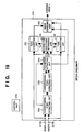
- Fig. 19 is a block diagram showing the arrangement of an image combining apparatus 210 and the process flow of an inputted image according to the second embodiment.
- the image combining apparatus 210 mainly includes: input terminals 210a and 210b; a corresponding-point-extracting unit 220 which extracts corresponding points from two input images; a corresponding-point-selecting unit 225 which removes components which are erroneously detected as corresponding points from a set of corresponding points extracted by the corresponding-point-extracting unit 220, and which selects only the correct corresponding points; a parameter estimating unit 240 which estimates parameters for combining images; a correction-coefficient-determining unit 230 which determines coefficients for tone correction of the image; tone converting units 231 and 232 which respectively correct tones of input images a and b; and an image combining unit 250 which combines two images on which tone conversion has been performed.
- Images a and b are respectively input to the input terminals 210a and 210b.
- the input images a and b are picked up by an electronic still camera or a video camera or the like in a manner such that both images partially include an overlapping region having the same image.
- the exposure conditions at the time of image pick-up are different for the two images.
- Each of the input terminals 210a and 210b is connected to the corresponding-point-extracting unit 220, correction-coefficient-determining unit 230, and tone converting units 231 and 232.
- the input images a and b are sent to the corresponding-point-extracting unit 220 where corresponding points are extracted from each of the images a and b.
- the corresponding-point-extracting unit 220 is connected to the corresponding-point-selecting unit 225 and the parameter estimating unit 240.
- the corresponding points extracted by the corresponding-point-extracting unit 220 are sent to the corresponding-point-selecting unit 225 and the parameter estimating unit 240.
- the corresponding-point-selecting unit 225 and the parameter estimating unit 240 are interactively connected to each other.
- the corresponding-point-selecting unit 225 On the basis of coordinates conversion parameters estimated by the parameter estimating unit 240 and a coordinates value indicative of the corresponding points extracted by the corresponding-point-extracting unit 220, the corresponding-point-selecting unit 225 removes components which are erroneously detected as corresponding points from the corresponding points extracted by the corresponding-point-extracting unit 220, and sends the result to the parameter estimating unit 240.
- the parameter estimating unit 240 estimates parameters for image conversion on the basis of the result where erroneous corresponding points have been removed.
- the parameter estimating unit 240 is connected to the correction-coefficient-determining unit 230 and image combining unit 250.
- the image conversion parameters estimated by the parameter estimating unit 240 is sent to the correction-coefficient-determining unit 230 and the image combining unit 250.
- the correction-coefficient-determining unit 230 which holds images a and b inputted by the input terminals 210a and 210b and image conversion parameters (A, B, C and D) estimated by the parameter estimating unit 240, determines coefficients (T a and T b ) for tone correction of an image on the basis of the image included in the overlapping region of the images a and b.
- the correction-coefficient-determining unit 230 is connected to the tone converting units 231 and 232.
- the correction-coefficient-determining unit 230 sends the determined coefficients (T a and T b ) to the tone converting units 231 and 232, respectively.
- the tone converting units 231 and 232 perform tone conversion on each of the images a and b utilizing the coefficient (T b ) sent by the correction-coefficient-determining unit 230, so that lightness is equal in the overlapping region of the images a and b.
- Each of the tone converting units 231 and 232 is connected to the image combining unit 250.
- the image combining unit 250 converts the images a and b, on which tone correction has been performed respectively by the tone converting units 231 and 232, by utilizing the parameters estimated by the parameter estimating unit 240 and combines the two images into a single image.
- control unit 270 controls the entire image combining apparatus.
- the second embodiment largely differs from the first embodiment by including the corresponding-point-selecting unit 225.
- the operation of the image combining apparatus 210 will be described in a case where a combined image c is generated based on the images a and b.
- the input images a and b each includes density image data having N number of tones.
- the input two images a and b are first sent to the corresponding-point-extracting unit 220 where corresponding points are extracted.
- the processing for extracting corresponding points performed by the corresponding-point-extracting unit 220 is substantially identical to the processing performed by the extracting unit 1 in the first embodiment.
- the extracting unit 220 in the second embodiment executes substantially the same processing steps as the extraction processing steps (Fig. 5) in the first embodiment. That is, the extracting unit 220 extracts a set of corresponding points by performing template matching.
- the corresponding-point-extracting unit 220 sends the extracted corresponding points to the parameter estimating unit 240 and the corresponding-point-selecting unit 225.
- the parameter estimating unit 240 estimates parameters (A, B, C and D) for coordinates conversion, on the basis of the extracted corresponding points.
- the second embodiment also requires coordinates conversion to coincide the overlapping region of the image a with the overlapping region of the image b.
- Affin transformation is employed as similar to the first embodiment.
- the parameter estimating unit 240 according to the second embodiment determines parameters A, B, C and D to be applied to the Affin transformation expressed by equation (3), and outputs the result to the correction-coefficient-determining unit 230.
- the estimating unit 240 according to the second embodiment is substantially identical to the estimating unit 3 according to the first embodiment.
- a set of corresponding points extracted by the corresponding-point-extracting unit 220 and coordinates conversion parameters (A, B, C and D) estimated by the parameter estimating unit 240 are input to the corresponding-point-selecting unit 225.
- the corresponding-point-selecting unit 225 removes erroneously detected corresponding points from the set of corresponding points extracted by the corresponding-point-extracting unit 220.
- corresponding points which will be utilized by the parameter estimating unit 240 for estimating image conversion parameters, are narrowed down to more appropriate values.
- the template matching, performed by the extracting unit 220 to extract corresponding points has a possibility of erroneous recognition. Therefore, the corresponding points must be reconfirmed by a method different from template matching.
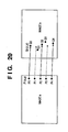
- Fig. 20 illustrates processing performed by the selecting unit 225 where determination is made as to whether or not the corresponding points are erroneously recognized.
- the corresponding-point-selecting unit 225 utilizes the Affin transformation parameters A, B, C and D obtained by the parameter estimating unit 240 to detect components of erroneous corresponding points in accordance with the following equation:
- (A•x+B•y+C) and (-B•x+A•y+ D) respectively indicate coordinates (x, y) of an arbitrary point (estimated to be one of corresponding points) on the image a on which Affin transformation has been performed. Accordingly, if an absolute value of the difference between the coordinates (A • x + B • y + C, -B • x + A • y + D), on which Affin transformation has been performed on (x, y), and coordinates (x', y') on the image b, is larger than a threshold value Th, (i.e. if equation (15) is not satisfied), the pair of corresponding points P i (x, y) and Q i (x', y') is considered to be erroneously recognized.
- Th i.e. if equation (15) is not satisfied
- the corresponding-point-selecting unit 225 selects only the corresponding points that satisfy equation (15) from the set of corresponding points obtained by the corresponding-point-extracting unit 220.
- arrows indicated by solid lines and broken lines represent movement of positions of the points according to Affin transformation.
- a pair of corresponding points indicated by the solid line e.g. a pair of points P 0 and Q 0 or a pair of points P 2 and Q 2
- a pair of corresponding points P 1 and Q 1 or a pair of points P 3 and Q 3 obtained by the corresponding-point-extracting unit 220 is deviated for more than a threshold value, from the coordinates obtained on the basis of aforementioned parameters.
- the corresponding-point-selecting unit 225 sends the result of selection to the parameter estimating unit 240.
- the parameter estimating unit 240 estimates parameters used for combining images by utilizing the selected corresponding points. As set forth above, parameters for combining images are estimated on the basis of coordinates of corresponding points from which erroneous components have been removed. Therefore, the image combining apparatus can generate a more precise combined image.
- the parameter estimating unit 240 sends the estimated parameters (A, B, C and D) to the correction-coefficient-determining unit 230.
- the correction-coefficient-determining unit 230 determines correction coefficients to be utilized by the tone converting units 231 and 232 for tone correction.
- Fig. 21 is a flowchart showing the tone correction processing performed by the correction-coefficient-determining unit 230 and tone converting units 231 and 232.
- Sample pixels are first obtained from images a and b to determine tone correction coefficients (step S31).
- Fig. 22 illustrates obtained sample pixels.
- the correction-coefficient-determining unit 230 first determines on the basis of the image combine parameters (A, B, C and D) estimated by the parameter estimating unit 240, as to whether or not a coordinates value of a sample pixel P a1 of the image a is within the overlapping region. To make determination, the correction-coefficient-determining unit 230 converts the coordinates value of a sample pixel P a1 of the image a into a coordinates value of image b by Affin transformation utilizing equation (3), and makes determination as to whether or not the converted coordinates value is included in the image b.
- a coordinates value corresponding to the sample pixel P a1 in the image b is set to be a sample pixel P b1 .
- the correction-coefficient-determining unit 230 may perform the sampling of pixel values pixel by pixel, or for every arbitrary number of pixels. Moreover, the correction-coefficient-determining unit 230 may utilize, as sample data, an average value of neighboring pixel values based on the coordinates of the corresponding points obtained by utilizing the image combine parameters.
- the correction-coefficient-determining unit 230 obtains tone correction coefficients of the image a on the basis of sample pixels P ak and P bk obtained in the foregoing manner (step S32).
- the tone correction coefficients are calculated as a coefficient of a tone correction function f a .
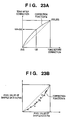
- Fig. 23A The method of performing tone correction according to the second embodiment will be described with reference to Fig. 23A.
- the abscissa indicates tones of an image before correction, and the ordinate indicates tones after correction.
- a correction function f a is determined so that the tones of the image a can be expressed by a quadratic function (tone correction function) passing through three points: (0, 0), (255, 255) and (128, 128+D/2).
- the tone correction function f a is defined to be T a1 , T a2 and T a3 .
- a value obtained by converting the sample pixel P ak of the image a utilizing the tone correction function f a is defined to be f a (P ak ).
- the correction-coefficient-determining unit 230 calculates coefficients (T b1 , T b2 and T b3 ) of the tone correction function f b of the image b (step S33).
- the tone correction function f b is obtained to be utilized as a function to coincide the sample pixel P bk with sample pixel f a (P ak ).
- the coefficients (T b1 , T b2 and T b3 ) of the tone correction function f b are calculated by the least squares method, utilizing the sample pixels shown in Fig. 23B, to minimize ⁇ in equation (17).
- ⁇ ⁇ f a (P ak ) - (T b1 ⁇ p bk 2 + T b2 ⁇ p bk + T b3 ) ⁇ 2
- the correction-coefficient-determining unit 230 sends the calculated tone correction coefficients T a and T b respectively to the tone converting units 231 and 232.
- the tone converting units 231 and 232 respectively convert each of the pixel values of images a and b utilizing each of the tone correction coefficients sent by the correction-coefficient-determining unit 230 (step S34).
- the operation of the tone converting unit 232 is described below. Note that the tone converting unit 231 executes the same operation as that of the tone converting unit 232.
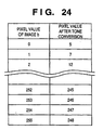
- a table is generated to convert tones of the image b on the basis of tone correction coefficients T b1 , T b2 and T b3 . More specifically, assuming that the dynamic range of the image is 8 bits, a table as shown in Fig. 24 is generated to convert a pixel value (0 to 255) of the image b into a pixel value f b (0) ⁇ f b (255) according to the quadratic function in equation (18).
- the tone converting unit may perform tone conversion for each of the colors R, G and B.
- the tone converting unit may perform tone conversion by generating a conversion function commonly used for the colors R, G and B in accordance with a luminance signal.
- the function f a which corrects tonality of the image a may be generated on the basis of pixel values of G image signals. All the R, G and B components of the image a may be converted by the function f a .
- Conversion functions f b for R, G, B colors of the image b are generated in such a manner that pixel values of each color component of the converted image b by f b may match with those of the image a converted by using the function f a .
- tone conversion may be performed by utilizing a non-linear table.
- the tone converting units 231 and 232 sends the images a and b, on which tone conversion has been performed, to the image combining unit 250 where the images are combined into a single image. Since the process of combining images is identical to that of the first embodiment (Fig. 11), detailed description thereof will be omitted.
- erroneously detected corresponding points are first determined in an overlapping region of images a and b partially having the same subject. Then, on the basis of a result of extracted corresponding points from which the erroneously detected corresponding points are removed, parameters (A, B, C and D) for combining the images are determined. Next, sample pixels (P ak and P bk ) used for tone correction are generated, utilizing the image combine parameters, and a tone correction coefficient (T a ) of the image a is calculated on the basis of an average value of the sample pixels.
- a tone correction coefficient (T b ) of the image b is calculated. Since the images a and b are combined after tone correction is performed on the images a and b utilizing each of the tone correction coefficients calculated in the foregoing manner, it is possible to generate a combined image whose boundary of the images is inconspicuous, even in a case where the two images have different exposure conditions.
- the corrected tones of the images a and b are natural.
- An image combining apparatus has the same arrangement as that of the second embodiment shown in Fig. 19. However, functions and operation of the corresponding-point-extracting unit 220, corresponding-point-selecting unit 225 and correction-coefficient-determining unit 230 are different from those of the second embodiment. Hereinafter, description thereof will be provided.
- the corresponding-point-extracting unit 220 of the image combining apparatus 210 does not determine (step S4 in Fig. 5) reliability of corresponding points obtained by matching operation. Instead, the third modified embodiment recognizes a position having a minimum value of non-coincidence as a corresponding point.
- the corresponding-point-selecting unit 225 repeats the process of removing erroneous corresponding points which is shown in the aforementioned equation (15), thereby enhancing accuracy in extracting corresponding points.
- Figs. 25A - 25C are explanatory views for explaining the steps of removing erroneous corresponding points performed by the corresponding-point-selecting unit 225.
- the parameter estimating unit calculates image conversion parameters A, B, C and D.
- the difference of each pair of corresponding points is then obtained in accordance with equation (15).
- average values Avg(dx) and Avg(dy) of the differences are calculated.
- the average value of the differences is used as a threshold value. More specifically, the corresponding-point-selecting unit 225 removes erroneously recognized corresponding points as shown in Fig. 25B utilizing the values Th x ⁇ Avg(dx) and Th y ⁇ Avg(dy).
- the corresponding-point-selecting unit 225 repeats the above processing until the average values Avg(dx) and Avg(dy) of the differences are converged to a predetermined value.
- the resultant corresponding points (Fig. 25C) are sent to the parameter estimating unit 240 where image combine parameters are estimated.
- the correction-coefficient-determining unit 230 obtains tone correction coefficients T a and T b on the basis of the sample pixels P ak and P bk obtained in the steps S32 and S33 in the flowchart in Fig. 21.
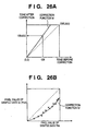
- Figs. 26A and 26B are graphs for explaining the steps of determining tone correction coefficients by the correction-coefficient-determining unit 230.
- the correction-coefficient-determining unit 230 calculates the average values Avg(P a ) and Avg(P b ) of the sample pixels P ak and P bk obtained from each of the images a and b, and further calculates difference D of each of the average values.
- tones of the image a are converted such that the tones are expressed by the linear function f a ' passing through the points (0, 0) and (128, 128+D/2).
- the sample pixel P ak of the image a is converted in accordance with the tone correction function f a ', and the converted sample pixel is defined to be f a '(P ak ).
- the coefficients of the tone correction function f a ' are T a1 ' and T a2 '.
- tone correction coefficient f b ' is generated to coincide the sample pixel P bk with the sample pixel f a '(P ak ).
- the abscissa in Fig. 26B indicates tones before correction, and the ordinate indicates tones corrected by utilizing the tone correction coefficient f b '.
- the coefficients T b1 , T b2 and T b3 utilized to generate the tone correction function f b ' are calculated by the least squares method utilizing the sample pixels shown in Fig. 26B, to minimize £ in equation (17).
- the corresponding-point-extracting unit does not determine the reliability of the corresponding points obtained by matching processing. Instead, a position having a minimum value of non-coincidence is recognized as a corresponding point. By virtue of this processing, it is possible to improve accuracy in extracting corresponding points.
- image combine parameters are set in accordance with the corresponding points having high precision from which erroneous corresponding points are removed. Further, the sample pixels for tone correction are generated by utilizing the image combine parameters. Therefore, it is possible to generate a combined image whose boundary of the images is inconspicuous, even in a case where the two images have different exposure conditions.
- the arrangement of the image combining apparatus according to the fourth modified embodiment is identical to that of the second embodiment shown in Fig. 19. However, the operation of the correction-coefficient-determining unit 230 is different from that of the second embodiment. Hereinafter the operation thereof will be described.
- the correction-coefficient-determining unit obtains the sample pixels P ak and P bk shown in Fig. 22 which are utilized to generate tone correction coefficients, from pixel values of corresponding points between the images a and b, which are obtained on the basis of Affin transformation parameters (A, B, C and D).
- matching processing is performed in the neighbor of coordinates of the corresponding points which are obtained on the basis of Affin transformation parameters, so that sample pixels are obtained with high precision.
- points P and P' are a pair of corresponding points obtained on the basis of Affin transformation parameters.
- the template T is generated with the point P as the center of the image a'.
- Matching operation is executed with respect to points in the template T, within the range of the searching objective area S of the image b' having a point P' as its center.
- the obtained corresponding point is defined as a point P" which precisely coincides with the point P. Accordingly, deviation of sample pixels conventionally generated due to errors in the parameters is corrected (an error generated between P'-P"), thus more accurate sample pixels are generated.
- the result of the matching processing is determined to be correct if a value of non-coincidence at a peak value is lower than a threshold value.
- sample pixels may be generated by utilizing coordinates of a corresponding point which is obtained by Affin transformation.
- the tone correction process of the images a' and b', generation process of a combined image c' performed by the image combining unit 250 are performed similar to that of the second embodiment.
- highly accurate sample pixels can be obtained by performing matching processing in the neighbor of the coordinates of the corresponding points obtained on the basis of Affin transformation parameters.
Landscapes
- Engineering & Computer Science (AREA)
- Multimedia (AREA)
- Signal Processing (AREA)
- Image Processing (AREA)
Claims (16)
- Vorrichtung zum Kombinieren eines ersten und eines zweiten Bildes mit überlappenden Regionen, mit
einer Identifizierungseinrichtung (1) zum Identifizieren der überlappenden Regionen durch Einstellen eines Suchbereichs (s) in einem Bild und Abtasten des anderen Bildes mit einem Vorlagenbereich (t) zum Extrahieren entsprechender Punkte in den zwei Bildern,
einer Umwandlungseinrichtung (2) zur Umwandlung des Koordinatensystems eines Bildes entsprechend dem Koordinatensystem des anderen Bildes,
einer Kombinationseinrichtung (2,6) zum Kombinieren des ersten und zweiten Bildes zur Erzeugung eines kombinierten Bildes,
einer Erfassungseinrichtung (3) zur Erfassung der Tonerdichte eines ersten, der überlappenden Region des ersten Bildes entsprechenden Teilbildes und der Tonetdichte eines zweiten, der überlappenden Region des zweiten Bildes entsprechenden Teilbildes auf der Grundlage der Ausgabe der Identifizierungseinrichtung, und
einer Tonkorrektureinrichtung (4,5) zur Durchführung einer Tonkorrektur bei zumindest einem der Teilbilder auf der Grundlage der Differenz der Tondichte, wie sie durch die Erfassungseinrichtung erfasst wird, so dass die Tondichten der zwei Teilbilder sich aneinander annähern, und
einer Einrichtung (6) zur Erzeugung einer Grenze, die die zwei Teilbilder trennt, wobei die Kombinationseinrichtung zur weiteren Korrektur der Ausgabe der Tonkorrektureinrichtung hinsichtlich der Entfernung jedes Bildelements in einer Ton-korrigierten Teilregion von der Grenze eingerichtet ist. - Vorrichtung nach Anspruch 1, wobei die Erfassungseinrichtung eine Berechnungseinrichtung zur Berechnung einer Korrekturfunktion umfasst, die eine Korrelation zwischen der Tondichte des ersten Teilbildes und der Tondichte des zweiten Teilbildes definiert, und die Tonkorrektureinrichtung zur Durchführung einer Tonkorrektur bei dem ersten Bild oder dem zweiten Bild unter Verwendung der berechneten Korrekturfunktion eingerichtet ist.
- Vorrichtung nach Anspruch 2, wobei die Berechnungseinrichtung zur Berechnung der Korrekturfunktion derart eingerichtet ist, dass die Korrekturfunktion durch eine quadratische Funktion genähert wird.
- Vorrichtung nach einem der vorhergehenden Ansprüche, wobei die Kombinationseinrichtung zum Hinzufügen von Gewichtungsfaktoren zu dem durch die Tonkorrektureinrichtung korrigierten Bild eingerichtet ist, wobei die Gewichtungsfaktoren auf der Entfernung von der Grenze beruhen.
- Vorrichtung nach einem der Ansprüche 1 bis 4, wobei die Kombinationseinrichtung zum Einstellen eines Tonumwandlungsbereichs in der Region der Überlappung zwischen den zwei Bildern eingerichtet ist.
- Vorrichtung nach Anspruch 5, wobei die Kombinationseinrichtung zur Durchführung einer Tonumwandlung lediglich bei dem zweiten Teilbild eingerichtet ist.
- Vorrichtung nach Anspruch 4 oder 5, wobei die Kombinationseinrichtung zur Änderung der Größe des Tonumwandlungsbereichs entsprechend der Differenz zwischen der Dichte des ersten Teilbildes und der Dichte des zweiten Teilbildes eingerichtet ist.
- Vorrichtung nach Anspruch 7, wobei die Kombinationseinrichtung zum Einstellen des Tonumwandlungsbereichs entsprechend der Differenz des Durchschnittsdichtewerts zwischen dem ersten Bild und dem zweiten Bild in der Region der Überlappung zwischen den zwei Bildern eingerichtet ist.
- Vorrichtung nach einem der vorhergehenden Ansprüche, wobei die Umwandlungseinrichtung zur Bestimmung einer Abbildung für eine Koordinatenumwandlung der Koordinaten des ersten Teilbildes in die Koordinaten des zweiten Teilbildes eingerichtet ist, und
die Kombinationseinrichtung zur Verwendung einer inversen Transformation der Abbildung zur Abbildung des zweiten Teilbildes auf die Koordinaten des ersten Teilbildes eingerichtet ist, wodurch das erste Bild und das zweite Bild kombiniert werden. - Vorrichtung nach einem der vorhergehenden Ansprüche, wobei die Identifizierungseinrichtung umfasst
eine Entfernungseinrichtung zur Entfernung von Daten aus dem extrahierten Satz entsprechender Punkte, die entsprechende Punkte angeben, die irrtümlich als entsprechende Punkte durch die Entsprechungspunktextrahiereinrichtung erfasst werden, auf der Grundlage von Koordinatenumwandlungsparametern, die unter Verwendung des Satzes entsprechender Punkte geschätzt werden, die durch die Entsprechungspunktextrahiereinrichtung extrahiert werden,
wobei die Kombinationseinrichtung zum Schätzen von Bildkombinationsparametern auf der Grundlage des Satzes entsprechender Punkte eingerichtet ist, aus dem falsche entsprechende Punkte entfernt wurden. - Vorrichtung nach Anspruch 10, wobei die Tonkorrektureinrichtung zur Erzeugung einer ersten Korrekturfunktion zur Durchführung einer Tonkorrektur bei dem ersten Bild auf der Grundlage der Differenz zwischen einem Durchschnittswert der aus dem ersten Bild extrahierten Bildelementwerte und dem Durchschnittswert der aus dem zweiten Bild extrahierten Bildelementwerte,
zur Durchführung einer Tonkorrektur bei dem ersten Bild unter Verwendung der ersten Korrekturfunktion,
zur Erzeugung einer zweiten Korrekturfunktion zum Zusammenfallen der Bildelementwerte der entsprechenden Punkte in dem zweiten Bild, aus denen die falschen entsprechenden Punkt durch die Entfernungseinrichtung entfernt wurden, mit den Bildelementwerten der entsprechenden Punkte in dem korrigierten ersten Bild, aus denen die falschen entsprechenden Punkte entfernt wurden, und
zur Durchführung einer Tonkorrektur bei dem zweiten Bild unter Verwendung der zweiten Korrekturfunktion eingerichtet ist. - Vorrichtung nach Anspruch 1, wobei die Tonkorrektureinrichtung (4,5) zur Durchführung einer Tonkorrektur bei einer Tonumwandlungsregion eingerichtet ist, die größer als die überlappende Region ist, so dass die Tondichte des zumindest einen Teilbildes sich an die andere annähert,
wobei die Kombinationseinrichtung das kombinierte Bild auf der Grundlage des ersten Bildes, des zweiten Bildes und zumindest eines der Teilbilder erzeugt, dessen Tondichte durch die Tonkorrektureinrichtung korrigiert wurde. - Verfahren zum Kombinieren eines ersten und zweiten Bildes mit überlappenden Regionen, mit
einem Schritt der Identifizierung der überlappenden Regionen durch Einstellen eines Suchbereichs (s) in einem Bild und Abtasten des anderen Bildes mit einem Vorlagenbereich (t), um entsprechende Punkte in den zwei Bildern zu extrahieren,
einem Schritt der Umwandlung des Koordinatensystems eines Bildes entsprechend dem Koordinatensystem des - anderen Bildes und
einem Schritt der Kombination des ersten und zweiten Bildes zur Erzeugung eines kombinierten Bildes, und
einem Schritt der Erfassung der Tondichte eines ersten, der überlappenden Region des ersten Bildes entsprechenden Teilbildes und der Tondichte eines zweiten, der überlappenden Region des zweiten Bildes entsprechenden Teilbildes auf der Grundlage der Ausgabe des Identifizierungsschritts und
einem Schritt der Erzeugung einer Grenzlinie, die die zwei Teilbilder trennt, wobei der Kombinationsschritt die Durchführung eines Schritts einer Tonkorrektur bei zumindest einem der Teilbilder auf der Grundlage der Differenz der Tondichte beinhaltet, wie sie durch den Erfassungsschritt erfasst wird, so dass die Tondichten der zwei Teilbilder sich aneinander annähern, und wobei der Kombinationsschritt ferner die Ausgabe des Tonkorrekturschritts hinsichtlich der Entfernung jedes Bildelements in einer Dichte-korrigierten Teilregion von der Grenze korrigiert. - Verfahren nach Anspruch 13, wobei der Identifizierungsschritt umfasst
Entfernen von Daten aus dem Satz extrahierter entsprechender Punkte, die entsprechende Punkte angeben, die Irrtümlich als entsprechende Punkte im Extrahierschritt erfasst werden, auf der Grundlage von Koordinatenumwandlungsparametern, die unter Verwendung des Satzes entsprechender Punkte geschätzt werden, die im Extrahierschritt extrahiert werden,
wobei im Kombinationsschritt Bildkombinationsparameter auf der Grundlage des Satzes entsprechender Punkte geschätzt werden, aus denen falsche entsprechende Punkte entfernt wurden. - verfahren nach Anspruch 14, wobei der Schritt der Durchführung einer Tonkorrektur die Schritte umfasst
Extrahieren von Bildelementwerten des Satzes entsprechender Punkte, aus denen die falschen entsprechenden Punkte entfernt wurden, jeweils aus dem ersten und zweiten Bild auf der Grundlage der geschätzten Bildkombinationsparameter und
Durchführen einer Tonkorrektur jeweils bei dem ersten und zweiten Bild unter Verwendung der extrahierten Bildelementwerte. - Verfahren nach Anspruch 14, wobei der Schritt der Durchführung der Tonkorrektur die Schritte umfasst
Erzeugen einer ersten Korrekturfunktion zur Durchführung einer Tonkorrektur bei der Teilregion des ersten Bildes auf der Grundlage der Differenz zwischen dem Durchschnittswert der aus dem ersten Bild extrahierten Bildelementwerte und dem Durchschnittswert der aus dem zweiten Bild extrahierten Bildelementwerte,
Durchführen einer Tonkorrektur bei der Teilregion des ersten Bildes unter Verwendung der ersten Korrekturfunktion,
Erzeugen einer zweiten Korrekturfunktion zum Zusammenfallen der Bildelementwerte der entsprechenden Punkte im zweiten Bild, aus denen die falschen entsprechenden Punkte im Entfernungsschritt entfernt wurden, mit den Bildelementwerten der entsprechenden Punkte im korrigierten ersten Bild, aus denen die falschen entsprechenden Punkte entfernt wurden, und
Durchführen einer Tonkorrektur bei dem zweiten Bild unter Verwendung der zweiten Korrekturfunktion.
Applications Claiming Priority (6)
| Application Number | Priority Date | Filing Date | Title |
|---|---|---|---|
| JP133642/96 | 1996-05-28 | ||
| JP13364296 | 1996-05-28 | ||
| JP8133642A JPH09321972A (ja) | 1996-05-28 | 1996-05-28 | 画像合成装置及び方法 |
| JP26020096 | 1996-09-10 | ||
| JP260200/96 | 1996-09-10 | ||
| JP8260200A JPH1091765A (ja) | 1996-09-10 | 1996-09-10 | 画像合成装置及びその方法 |
Publications (3)
| Publication Number | Publication Date |
|---|---|
| EP0810776A2 EP0810776A2 (de) | 1997-12-03 |
| EP0810776A3 EP0810776A3 (de) | 1998-11-25 |
| EP0810776B1 true EP0810776B1 (de) | 2003-10-15 |
Family
ID=26467953
Family Applications (1)
| Application Number | Title | Priority Date | Filing Date |
|---|---|---|---|
| EP97303567A Expired - Lifetime EP0810776B1 (de) | 1996-05-28 | 1997-05-27 | Bildkombinationsgerät und -verfahren |
Country Status (3)
| Country | Link |
|---|---|
| US (1) | US5982951A (de) |
| EP (1) | EP0810776B1 (de) |
| DE (1) | DE69725505T2 (de) |
Cited By (3)
| Publication number | Priority date | Publication date | Assignee | Title |
|---|---|---|---|---|
| RU2369034C2 (ru) * | 2005-06-20 | 2009-09-27 | Кэнон Кабусики Кайся | Устройство комбинирования изображений и способ и программа управления им |
| CN102903091A (zh) * | 2011-06-15 | 2013-01-30 | 三星泰科威株式会社 | 用于在数字图像处理设备中拼接图像的方法 |
| CN106157273A (zh) * | 2015-03-30 | 2016-11-23 | 阿里巴巴集团控股有限公司 | 生成合成图片的方法及装置 |
Families Citing this family (268)
| Publication number | Priority date | Publication date | Assignee | Title |
|---|---|---|---|---|
| DE69733946T2 (de) | 1996-05-10 | 2006-05-24 | Eastman Kodak Co. | Farbsensor mit luminanzpriorität |
| US6069714A (en) | 1996-12-05 | 2000-05-30 | Applied Science Fiction, Inc. | Method and apparatus for reducing noise in electronic film development |
| US6442301B1 (en) | 1997-01-06 | 2002-08-27 | Applied Science Fiction, Inc. | Apparatus and method for defect channel nulling |
| US6380539B1 (en) | 1997-01-30 | 2002-04-30 | Applied Science Fiction, Inc. | Four color trilinear CCD scanning |
| US6017688A (en) | 1997-01-30 | 2000-01-25 | Applied Science Fiction, Inc. | System and method for latent film recovery in electronic film development |
| JPH10232940A (ja) * | 1997-02-20 | 1998-09-02 | Sony Corp | コーナ検出装置及びコーナ検出方法 |
| JPH10334212A (ja) * | 1997-04-01 | 1998-12-18 | Fuji Photo Film Co Ltd | 付加情報付き画像ファイルからの画像プリントシステム |
| JP3773011B2 (ja) * | 1997-06-20 | 2006-05-10 | シャープ株式会社 | 画像合成処理方法 |
| US6215914B1 (en) * | 1997-06-24 | 2001-04-10 | Sharp Kabushiki Kaisha | Picture processing apparatus |
| US6128108A (en) * | 1997-09-03 | 2000-10-03 | Mgi Software Corporation | Method and system for compositing images |
| US6466701B1 (en) * | 1997-09-10 | 2002-10-15 | Ricoh Company, Ltd. | System and method for displaying an image indicating a positional relation between partially overlapping images |
| DE69833302T2 (de) * | 1997-10-06 | 2006-11-02 | Canon K.K. | Verfahren und Vorrichtung zur Bildsynthese |
| EP1025517A1 (de) * | 1997-10-27 | 2000-08-09 | Massachusetts Institute Of Technology | Bildsuch- und wiederauffindungssystem |
| US6720997B1 (en) * | 1997-12-26 | 2004-04-13 | Minolta Co., Ltd. | Image generating apparatus |
| JPH11205648A (ja) * | 1998-01-09 | 1999-07-30 | Olympus Optical Co Ltd | 画像合成装置 |
| AU2563199A (en) | 1998-02-04 | 1999-08-23 | Applied Science Fiction, Inc. | Multilinear array sensor with an infrared line |
| US6512601B1 (en) | 1998-02-23 | 2003-01-28 | Applied Science Fiction, Inc. | Progressive area scan in electronic film development |
| JPH11250222A (ja) * | 1998-02-27 | 1999-09-17 | Canon Inc | 画像処理方法及びその装置 |
| US6393160B1 (en) | 1998-03-13 | 2002-05-21 | Applied Science Fiction | Image defect correction in transform space |
| US6002804A (en) * | 1998-03-26 | 1999-12-14 | Hewlett-Packard Company | Tone dependent variable halftoning with adjustable algorithm selection |
| US6801339B1 (en) * | 1998-03-26 | 2004-10-05 | Fuji Photo Film Co., Ltd. | Image processing method and apparatus |
| JP3726223B2 (ja) * | 1998-03-27 | 2005-12-14 | 富士写真フイルム株式会社 | 画像処理装置 |
| IT1312245B1 (it) * | 1998-04-10 | 2002-04-09 | Ricoh Kk | Apparecchiatura, procedimento di elaborazione di immagini e supportodi registrazione leggibile da elaboratore con programma registrato su |
| US7067473B1 (en) * | 1998-07-14 | 2006-06-27 | Janssen Pharmaceutica N.V. | Neurotrophic growth factor |
| JP3370605B2 (ja) * | 1998-07-14 | 2003-01-27 | 富士通株式会社 | 3次元モデルの最適化装置および方法 |
| US6594041B1 (en) | 1998-11-20 | 2003-07-15 | Applied Science Fiction, Inc. | Log time processing and stitching system |
| US6704042B2 (en) * | 1998-12-10 | 2004-03-09 | Canon Kabushiki Kaisha | Video processing apparatus, control method therefor, and storage medium |
| US7558438B1 (en) | 1998-12-15 | 2009-07-07 | Fujifilm Corporation | System for synthesizing divisional images based on information indicating relationship between a series of divisional images |
| US6714249B2 (en) * | 1998-12-31 | 2004-03-30 | Eastman Kodak Company | Producing panoramic digital images by digital camera systems |
| US6437358B1 (en) | 1999-02-04 | 2002-08-20 | Applied Science Fiction, Inc. | Apparatus and methods for capturing defect data |
| US6404516B1 (en) | 1999-02-22 | 2002-06-11 | Applied Science Fiction, Inc. | Parametric image stitching |
| JP3808231B2 (ja) * | 1999-03-01 | 2006-08-09 | 富士写真フイルム株式会社 | 画像合成方法および装置並びに記録媒体 |
| US6781620B1 (en) | 1999-03-16 | 2004-08-24 | Eastman Kodak Company | Mixed-element stitching and noise reduction system |
| US7050085B1 (en) * | 2000-10-26 | 2006-05-23 | Imove, Inc. | System and method for camera calibration |
| US7620909B2 (en) * | 1999-05-12 | 2009-11-17 | Imove Inc. | Interactive image seamer for panoramic images |
| US20040075738A1 (en) * | 1999-05-12 | 2004-04-22 | Sean Burke | Spherical surveillance system architecture |
| JP3867883B2 (ja) * | 1999-06-01 | 2007-01-17 | 株式会社リコー | 画像合成処理方法、画像合成処理装置及び記録媒体 |
| TW495389B (en) | 1999-06-29 | 2002-07-21 | Applied Science Fiction Inc | Slot coater device for applying developer to film for electronic film development |
| US7015954B1 (en) | 1999-08-09 | 2006-03-21 | Fuji Xerox Co., Ltd. | Automatic video system using multiple cameras |
| WO2001013174A1 (en) | 1999-08-17 | 2001-02-22 | Applied Science Fiction, Inc. | Method and system for using calibration patches in electronic film processing |
| JP4169462B2 (ja) * | 1999-08-26 | 2008-10-22 | 株式会社リコー | 画像処理方法及び装置、デジタルカメラ、画像処理システム、並びに、画像処理プログラムを記録した記録媒体 |
| JP4143228B2 (ja) * | 1999-08-27 | 2008-09-03 | キヤノン株式会社 | 画像処理装置、画像処理方法および記憶媒体 |
| US6487321B1 (en) | 1999-09-16 | 2002-11-26 | Applied Science Fiction | Method and system for altering defects in a digital image |
| AU1962701A (en) | 1999-10-08 | 2001-04-23 | Applied Science Fiction, Inc. | System and method for correcting defects in digital images through selective fill-in from surrounding areas |
| EP1226710A1 (de) | 1999-10-08 | 2002-07-31 | Applied Science Fiction | Verfahren und gerät für bildaufzeichnung und fehlerbehandlung mit differentieller beleuchtung |
| US6924911B1 (en) | 1999-10-12 | 2005-08-02 | Eastman Kodak Company | Method and system for multi-sensor signal detection |
| US6711302B1 (en) | 1999-10-20 | 2004-03-23 | Eastman Kodak Company | Method and system for altering defects in digital image |
| JP2001223862A (ja) * | 1999-12-02 | 2001-08-17 | Fuji Photo Film Co Ltd | 原稿読取装置及び方法 |
| WO2001045042A1 (en) | 1999-12-17 | 2001-06-21 | Applied Science Fiction, Inc. | Method and system for selective enhancement of image data |
| US6683995B2 (en) | 1999-12-23 | 2004-01-27 | Eastman Kodak Company | Method and apparatus for correcting large defects in digital images |
| US7164511B2 (en) * | 1999-12-29 | 2007-01-16 | Eastman Kodak Company | Distinguishing positive and negative films system and method |
| US6704458B2 (en) | 1999-12-29 | 2004-03-09 | Eastman Kodak Company | Method and apparatus for correcting heavily damaged images |
| US6720560B1 (en) | 1999-12-30 | 2004-04-13 | Eastman Kodak Company | Method and apparatus for scanning images |
| US6965692B1 (en) | 1999-12-30 | 2005-11-15 | Eastman Kodak Company | Method and apparatus for improving the quality of reconstructed information |
| US6813392B2 (en) | 1999-12-30 | 2004-11-02 | Eastman Kodak Company | Method and apparatus for aligning multiple scans of the same area of a medium using mathematical correlation |
| US6554504B2 (en) | 1999-12-30 | 2003-04-29 | Applied Science Fiction, Inc. | Distributed digital film processing system and method |
| US6862117B1 (en) | 1999-12-30 | 2005-03-01 | Eastman Kodak Company | Method and apparatus for reducing the effect of bleed-through on captured images |
| US6864973B2 (en) | 1999-12-30 | 2005-03-08 | Eastman Kodak Company | Method and apparatus to pre-scan and pre-treat film for improved digital film processing handling |
| AU2742701A (en) | 1999-12-30 | 2001-07-16 | Applied Science Fiction, Inc. | Improved system and method for digital film development using visible light |
| US6505977B2 (en) | 1999-12-30 | 2003-01-14 | Applied Science Fiction, Inc. | System and method for digital color dye film processing |
| US6540416B2 (en) | 1999-12-30 | 2003-04-01 | Applied Science Fiction, Inc. | System and method for digital film development using visible light |
| US6788335B2 (en) | 1999-12-30 | 2004-09-07 | Eastman Kodak Company | Pulsed illumination signal modulation control & adjustment method and system |
| US6707557B2 (en) | 1999-12-30 | 2004-03-16 | Eastman Kodak Company | Method and system for estimating sensor dark current drift and sensor/illumination non-uniformities |
| US6447178B2 (en) | 1999-12-30 | 2002-09-10 | Applied Science Fiction, Inc. | System, method, and apparatus for providing multiple extrusion widths |
| US6717608B1 (en) * | 1999-12-31 | 2004-04-06 | Stmicroelectronics, Inc. | Motion estimation for panoramic digital camera |
| US6475711B1 (en) | 1999-12-31 | 2002-11-05 | Applied Science Fiction, Inc. | Photographic element and digital film processing method using same |
| WO2001050192A1 (en) | 1999-12-31 | 2001-07-12 | Applied Science Fiction, Inc. | Digital film processing method |
| US6456323B1 (en) * | 1999-12-31 | 2002-09-24 | Stmicroelectronics, Inc. | Color correction estimation for panoramic digital camera |
| AU2001236693A1 (en) | 2000-02-03 | 2001-08-14 | Applied Science Fiction | Film processing solution cartridge and method for developing and digitizing film |
| AU2001238021A1 (en) | 2000-02-03 | 2001-08-14 | Applied Science Fiction | Match blur system and method |
| AU2001238039A1 (en) | 2000-02-03 | 2001-08-14 | Applied Science Fiction | Method, system and software for signal processing using sheep and shepherd artifacts |
| US6619863B2 (en) | 2000-02-03 | 2003-09-16 | Eastman Kodak Company | Method and system for capturing film images |
| WO2001057796A2 (en) | 2000-02-03 | 2001-08-09 | Applied Science Fiction | Method, system, and software for signal processing using pyramidal decomposition |
| JP3849385B2 (ja) * | 2000-02-03 | 2006-11-22 | コニカミノルタホールディングス株式会社 | 画像処理装置、画像処理方法および画像処理プログラムを記録したコンピュータ読取可能な記録媒体 |
| US6786655B2 (en) | 2000-02-03 | 2004-09-07 | Eastman Kodak Company | Method and system for self-service film processing |
| US7262778B1 (en) | 2000-02-11 | 2007-08-28 | Sony Corporation | Automatic color adjustment of a template design |
| US6993719B1 (en) | 2000-02-11 | 2006-01-31 | Sony Corporation | System and method for animated character photo-editing interface and cross-platform education icon |
| US7136528B2 (en) | 2000-02-11 | 2006-11-14 | Sony Corporation | System and method for editing digital images |
| JP4541482B2 (ja) * | 2000-02-29 | 2010-09-08 | キヤノン株式会社 | 画像処理装置及び画像処理方法 |
| US6978051B2 (en) * | 2000-03-06 | 2005-12-20 | Sony Corporation | System and method for capturing adjacent images by utilizing a panorama mode |
| US7221395B2 (en) * | 2000-03-14 | 2007-05-22 | Fuji Photo Film Co., Ltd. | Digital camera and method for compositing images |
| GB2360413A (en) * | 2000-03-16 | 2001-09-19 | Lee Scott Friend | Wide angle parabolic imaging and image mapping apparatus |
| JP2001333348A (ja) * | 2000-05-24 | 2001-11-30 | Minolta Co Ltd | 送信装置、受信装置、放送システムおよび放送方法 |
| US6813391B1 (en) * | 2000-07-07 | 2004-11-02 | Microsoft Corp. | System and method for exposure compensation |
| US7313289B2 (en) * | 2000-08-30 | 2007-12-25 | Ricoh Company, Ltd. | Image processing method and apparatus and computer-readable storage medium using improved distortion correction |
| US20020176113A1 (en) | 2000-09-21 | 2002-11-28 | Edgar Albert D. | Dynamic image correction and imaging systems |
| US20020106134A1 (en) * | 2000-09-22 | 2002-08-08 | Dundon Thomas A. | Multiple-orientation image defect detection and correction |
| WO2002025345A2 (en) * | 2000-09-22 | 2002-03-28 | Applied Science Fiction | Lens focusing device, system and method for use with multiple light wavelengths |
| GB2369260B (en) * | 2000-10-27 | 2005-01-19 | Canon Kk | Method and apparatus for the generation of composite images |
| US6888997B2 (en) | 2000-12-05 | 2005-05-03 | Eastman Kodak Company | Waveguide device and optical transfer system for directing light to an image plane |
| EP1342211A2 (de) | 2000-12-07 | 2003-09-10 | Just Iced Cubed Inventions Inc. | Anordnungen und verfahren der ortungszurückstellung hemispherischer bilder zur panoramischen betrachtung |
| US20020131651A1 (en) * | 2001-01-12 | 2002-09-19 | Chandrashekhara Anantharamu | System and method for reducing images including graphs |
| JP2004523793A (ja) | 2001-02-09 | 2004-08-05 | イーストマン コダック カンパニー | デジタルフィルム処理液およびデジタルフィルムの処理方法 |
| JP3539394B2 (ja) * | 2001-03-26 | 2004-07-07 | ミノルタ株式会社 | 画像処理装置、プログラムおよび記録媒体 |
| US20020176116A1 (en) * | 2001-04-12 | 2002-11-28 | Rhoads Geoffrey B. | Digital watermarks as a communication channel in documents for controlling document processing devices |
| US6987892B2 (en) * | 2001-04-19 | 2006-01-17 | Eastman Kodak Company | Method, system and software for correcting image defects |
| JP3297040B1 (ja) * | 2001-04-24 | 2002-07-02 | 松下電器産業株式会社 | 車載カメラの画像合成表示方法及びその装置 |
| EP1384046B1 (de) * | 2001-05-04 | 2018-10-03 | Vexcel Imaging GmbH | Digitalkamera und verfahren zum erzeugen von sich überdeckenden bildern |
| US7791626B2 (en) | 2001-05-30 | 2010-09-07 | Zink Imaging, Inc. | Print head pulsing techniques for multicolor printers |
| US8377844B2 (en) | 2001-05-30 | 2013-02-19 | Zink Imaging, Inc. | Thermally-insulating layers and direct thermal imaging members containing same |
| US7830405B2 (en) | 2005-06-23 | 2010-11-09 | Zink Imaging, Inc. | Print head pulsing techniques for multicolor printers |
| US7388686B2 (en) * | 2003-02-25 | 2008-06-17 | Zink Imaging, Llc | Image stitching for a multi-head printer |
| US6805501B2 (en) | 2001-07-16 | 2004-10-19 | Eastman Kodak Company | System and method for digital film development using visible light |
| JP2003153080A (ja) * | 2001-11-09 | 2003-05-23 | Matsushita Electric Ind Co Ltd | 映像合成装置 |
| US7263240B2 (en) | 2002-01-14 | 2007-08-28 | Eastman Kodak Company | Method, system, and software for improving signal quality using pyramidal decomposition |
| US6978052B2 (en) * | 2002-01-28 | 2005-12-20 | Hewlett-Packard Development Company, L.P. | Alignment of images for stitching |
| US20030151689A1 (en) * | 2002-02-11 | 2003-08-14 | Murphy Charles Douglas | Digital images with composite exposure |
| JP2003259110A (ja) * | 2002-02-28 | 2003-09-12 | Fujitsu Ltd | 画像結合装置、その方法、プログラム |
| JP4097980B2 (ja) * | 2002-04-23 | 2008-06-11 | オリンパス株式会社 | 画像合成装置 |
| EP1379073A1 (de) * | 2002-07-03 | 2004-01-07 | Siemens Aktiengesellschaft | Bildaufnahmeverfahren für ein Panoramabild |
| JP3845045B2 (ja) * | 2002-07-23 | 2006-11-15 | 株式会社リコー | 画像処理装置、画像処理方法、画像形成装置、印刷装置及びホストpc |
| US7315324B2 (en) * | 2002-08-15 | 2008-01-01 | Dixon Cleveland | Motion clutter suppression for image-subtracting cameras |
| US7893957B2 (en) | 2002-08-28 | 2011-02-22 | Visual Intelligence, LP | Retinal array compound camera system |
| US8994822B2 (en) | 2002-08-28 | 2015-03-31 | Visual Intelligence Lp | Infrastructure mapping system and method |
| US8483960B2 (en) | 2002-09-20 | 2013-07-09 | Visual Intelligence, LP | Self-calibrated, remote imaging and data processing system |
| US6928194B2 (en) * | 2002-09-19 | 2005-08-09 | M7 Visual Intelligence, Lp | System for mosaicing digital ortho-images |
| USRE49105E1 (en) | 2002-09-20 | 2022-06-14 | Vi Technologies, Llc | Self-calibrated, remote imaging and data processing system |
| US7729511B2 (en) * | 2002-09-24 | 2010-06-01 | Pilz Gmbh & Co. Kg | Method and device for safeguarding a hazardous area |
| JP2004153691A (ja) * | 2002-10-31 | 2004-05-27 | Casio Comput Co Ltd | 撮像装置、撮像方法及びプログラム |
| JP2004334843A (ja) * | 2003-04-15 | 2004-11-25 | Seiko Epson Corp | 複数の画像から画像を合成する方法 |
| US7236646B1 (en) | 2003-04-25 | 2007-06-26 | Orbimage Si Opco, Inc. | Tonal balancing of multiple images |
| JP2005027206A (ja) * | 2003-07-01 | 2005-01-27 | Nikon Corp | 階調変換処理装置、電子カメラおよび階調変換プログラム |
| CN100338631C (zh) * | 2003-07-03 | 2007-09-19 | 马堃 | 数字成像设备现场全景成像的方法 |
| JP3838243B2 (ja) * | 2003-09-04 | 2006-10-25 | ソニー株式会社 | 画像処理方法、および画像処理装置、並びにコンピュータ・プログラム |
| WO2005024723A1 (ja) * | 2003-09-08 | 2005-03-17 | Nec Corporation | 画像合成システム、画像合成方法及びプログラム |
| US7606441B2 (en) * | 2003-11-27 | 2009-10-20 | Seiko Epson Corporation | Image processing device and a method for the same |
| JP4847685B2 (ja) * | 2004-04-16 | 2011-12-28 | 株式会社日立ハイテクノロジーズ | パターンサーチ方法 |
| US7653260B2 (en) * | 2004-06-17 | 2010-01-26 | Carl Zeis MicroImaging GmbH | System and method of registering field of view |
| US7375745B2 (en) * | 2004-09-03 | 2008-05-20 | Seiko Epson Corporation | Method for digital image stitching and apparatus for performing the same |
| US7756358B2 (en) * | 2004-11-30 | 2010-07-13 | Hewlett-Packard Development Company, L.P. | System and method of aligning images |
| US20060115182A1 (en) * | 2004-11-30 | 2006-06-01 | Yining Deng | System and method of intensity correction |
| US7646400B2 (en) | 2005-02-11 | 2010-01-12 | Creative Technology Ltd | Method and apparatus for forming a panoramic image |
| US7450137B2 (en) * | 2005-02-18 | 2008-11-11 | Hewlett-Packard Development Company, L.P. | System and method for blending images |
| US7634152B2 (en) | 2005-03-07 | 2009-12-15 | Hewlett-Packard Development Company, L.P. | System and method for correcting image vignetting |
| US7424218B2 (en) * | 2005-07-28 | 2008-09-09 | Microsoft Corporation | Real-time preview for panoramic images |
| US7930627B2 (en) * | 2005-09-22 | 2011-04-19 | Konica Minolta Systems Laboratory, Inc. | Office document matching method and apparatus |
| US7551802B2 (en) * | 2005-09-22 | 2009-06-23 | Konica Minolta Systems Laboratory, Inc. | Map image matching method and apparatus |
| US7630582B2 (en) * | 2005-11-15 | 2009-12-08 | Lexmark International, Inc. | Rendering optimization method and system |
| US7848596B2 (en) * | 2006-05-24 | 2010-12-07 | Hewlett-Packard Development Company, L.P. | Templated collage generation with occlusion costing |
| DE102006036933B4 (de) * | 2006-08-08 | 2024-01-11 | Bayerische Motoren Werke Aktiengesellschaft | Verfahren zur Erzeugung eines Gesamtbilds aus überlappenden Einzelbildern |
| JP4750854B2 (ja) * | 2006-09-14 | 2011-08-17 | 富士通株式会社 | 画像処理方法および装置とそのプログラム |
| JP4892010B2 (ja) * | 2007-01-30 | 2012-03-07 | 富士通株式会社 | 画像生成プログラム、画像生成装置、画像生成方法 |
| US8098956B2 (en) * | 2007-03-23 | 2012-01-17 | Vantana Medical Systems, Inc. | Digital microscope slide scanning system and methods |
| US8200039B2 (en) * | 2007-04-05 | 2012-06-12 | Adobe Systems Incorporated | Laying out multiple images |
| US8203764B2 (en) * | 2007-06-27 | 2012-06-19 | Lexmark International, Inc. | Phased illumination method for image capture system |
| KR101354899B1 (ko) * | 2007-08-29 | 2014-01-27 | 삼성전자주식회사 | 파노라마 사진 촬영 방법 |
| JP5223318B2 (ja) * | 2007-12-07 | 2013-06-26 | ソニー株式会社 | 画像処理装置、画像処理方法およびプログラム |
| JP4678404B2 (ja) * | 2007-12-27 | 2011-04-27 | ソニー株式会社 | 撮像装置、その制御方法およびプログラム |
| TWI361396B (en) * | 2008-01-18 | 2012-04-01 | Univ Nat Chiao Tung | Image synthesis system for a vehicle and the manufacturing method thereof mage synthesis device and method |
| TWI383680B (zh) * | 2008-04-10 | 2013-01-21 | Univ Nat Chiao Tung | 整合式影像監視系統及其方法 |
| KR20110016505A (ko) * | 2008-06-17 | 2011-02-17 | 코닌클리케 필립스 일렉트로닉스 엔.브이. | 컬러 조정 |
| US8139883B2 (en) * | 2008-07-29 | 2012-03-20 | Sony Corporation | System and method for image and video encoding artifacts reduction and quality improvement |
| KR101496467B1 (ko) | 2008-09-12 | 2015-02-26 | 엘지전자 주식회사 | 파노라마 촬영 기능이 구비된 이동 단말기 및 그의 동작방법 |
| US20100194851A1 (en) * | 2009-02-03 | 2010-08-05 | Aricent Inc. | Panorama image stitching |
| JP2011005050A (ja) * | 2009-06-26 | 2011-01-13 | Canon Inc | 画像処理方法及び画像処理装置 |
| US8385689B2 (en) * | 2009-10-21 | 2013-02-26 | MindTree Limited | Image alignment using translation invariant feature matching |
| KR20110052124A (ko) * | 2009-11-12 | 2011-05-18 | 삼성전자주식회사 | 파노라마 이미지 생성 및 조회 방법과 이를 이용한 휴대 단말기 |
| US20110141226A1 (en) * | 2009-12-11 | 2011-06-16 | Fotonation Ireland Limited | Panorama imaging based on a lo-res map |
| US10080006B2 (en) | 2009-12-11 | 2018-09-18 | Fotonation Limited | Stereoscopic (3D) panorama creation on handheld device |
| EP2545411B1 (de) * | 2009-12-11 | 2014-02-12 | DigitalOptics Corporation Europe Limited | Panoramabildgebung |
| US20110141229A1 (en) * | 2009-12-11 | 2011-06-16 | Fotonation Ireland Limited | Panorama imaging using super-resolution |
| US8294748B2 (en) * | 2009-12-11 | 2012-10-23 | DigitalOptics Corporation Europe Limited | Panorama imaging using a blending map |
| US20110141224A1 (en) * | 2009-12-11 | 2011-06-16 | Fotonation Ireland Limited | Panorama Imaging Using Lo-Res Images |
| US20110141225A1 (en) * | 2009-12-11 | 2011-06-16 | Fotonation Ireland Limited | Panorama Imaging Based on Low-Res Images |
| WO2011105988A1 (en) * | 2010-02-24 | 2011-09-01 | Thomson Licensing | Split screen for 3d |
| US9311708B2 (en) * | 2014-04-23 | 2016-04-12 | Microsoft Technology Licensing, Llc | Collaborative alignment of images |
| US9508011B2 (en) | 2010-05-10 | 2016-11-29 | Videosurf, Inc. | Video visual and audio query |
| US9413477B2 (en) | 2010-05-10 | 2016-08-09 | Microsoft Technology Licensing, Llc | Screen detector |
| EP2622836B1 (de) * | 2010-10-01 | 2015-07-22 | Contex A/s | Zweidimensionale kalibrierung einer bildsensorausrichtung bei optischen abtastern |
| CN102741878B (zh) | 2010-10-26 | 2015-08-19 | 株式会社摩如富 | 图像处理装置、图像处理方法以及图像处理程序 |
| CN101984463A (zh) * | 2010-11-02 | 2011-03-09 | 中兴通讯股份有限公司 | 全景图合成方法及装置 |
| JP2012105145A (ja) * | 2010-11-11 | 2012-05-31 | Canon Inc | 画像処理装置、画像処理方法、及び、プログラム |
| EP2548368B1 (de) | 2010-11-29 | 2013-09-18 | DigitalOptics Corporation Europe Limited | Zusammensetzung eines porträtbildes aus mehreren mit einer tragbaren vorrichtung aufgenommenen bildern |
| JP5682304B2 (ja) * | 2010-12-27 | 2015-03-11 | トヨタ自動車株式会社 | 画像提供装置 |
| US20120268626A1 (en) * | 2011-04-25 | 2012-10-25 | Avermedia Information, Inc. | Apparatus and method for eliminating glare |
| KR101913837B1 (ko) * | 2011-11-29 | 2018-11-01 | 삼성전자주식회사 | 파노라마 영상 생성 방법 및 이를 적용한 영상기기 |
| TW201324023A (zh) * | 2011-12-13 | 2013-06-16 | Fih Hong Kong Ltd | 全景拍照系統及方法 |
| DE102012016865B4 (de) * | 2012-08-25 | 2022-12-15 | Connaught Electronics Ltd. | Verbessertes Alpha-Blending von Bildern eines Kamerasystems eines Kraftfahrzeugs |
| CN113259565B (zh) | 2012-11-28 | 2023-05-19 | 核心光电有限公司 | 多孔径成像系统 |
| US9568713B2 (en) | 2013-01-05 | 2017-02-14 | Light Labs Inc. | Methods and apparatus for using multiple optical chains in parallel to support separate color-capture |
| US9185291B1 (en) | 2013-06-13 | 2015-11-10 | Corephotonics Ltd. | Dual aperture zoom digital camera |
| CN108535839B (zh) | 2013-07-04 | 2022-02-08 | 核心光电有限公司 | 小型长焦透镜套件 |
| JP5929849B2 (ja) | 2013-07-08 | 2016-06-08 | 株式会社デンソー | 画像生成装置、画像生成方法及び画像生成プログラム |
| CN108989649B (zh) | 2013-08-01 | 2021-03-19 | 核心光电有限公司 | 具有自动聚焦的纤薄多孔径成像系统及其使用方法 |
| US9374514B2 (en) | 2013-10-18 | 2016-06-21 | The Lightco Inc. | Methods and apparatus relating to a camera including multiple optical chains |
| US9549127B2 (en) | 2013-10-18 | 2017-01-17 | Light Labs Inc. | Image capture control methods and apparatus |
| US9423588B2 (en) | 2013-10-18 | 2016-08-23 | The Lightco Inc. | Methods and apparatus for supporting zoom operations |
| US9467627B2 (en) | 2013-10-26 | 2016-10-11 | The Lightco Inc. | Methods and apparatus for use with multiple optical chains |
| US9736365B2 (en) | 2013-10-26 | 2017-08-15 | Light Labs Inc. | Zoom related methods and apparatus |
| US9426365B2 (en) | 2013-11-01 | 2016-08-23 | The Lightco Inc. | Image stabilization related methods and apparatus |
| US9554031B2 (en) | 2013-12-31 | 2017-01-24 | Light Labs Inc. | Camera focusing related methods and apparatus |
| JP5889495B2 (ja) * | 2014-02-14 | 2016-03-22 | オリンパス株式会社 | 内視鏡システム |
| US9979878B2 (en) | 2014-02-21 | 2018-05-22 | Light Labs Inc. | Intuitive camera user interface methods and apparatus |
| US9462170B2 (en) | 2014-02-21 | 2016-10-04 | The Lightco Inc. | Lighting methods and apparatus |
| EP3164831A4 (de) | 2014-07-04 | 2018-02-14 | Light Labs Inc. | Verfahren und vorrichtung bezüglich der detektion von und/oder dem hinweis auf einen schmutzigen linsenzustand |
| US10110794B2 (en) | 2014-07-09 | 2018-10-23 | Light Labs Inc. | Camera device including multiple optical chains and related methods |
| US9392188B2 (en) | 2014-08-10 | 2016-07-12 | Corephotonics Ltd. | Zoom dual-aperture camera with folded lens |
| WO2016061565A1 (en) | 2014-10-17 | 2016-04-21 | The Lightco Inc. | Methods and apparatus for using a camera device to support multiple modes of operation |
| EP3235243A4 (de) | 2014-12-17 | 2018-06-20 | Light Labs Inc. | Verfahren und vorrichtung zur implementierung und verwendung von kameravorrichtungen |
| US9544503B2 (en) | 2014-12-30 | 2017-01-10 | Light Labs Inc. | Exposure control methods and apparatus |
| CN112327463B (zh) | 2015-01-03 | 2022-10-14 | 核心光电有限公司 | 微型长焦镜头模块和使用该镜头模块的相机 |
| KR101914894B1 (ko) | 2015-04-02 | 2018-11-02 | 코어포토닉스 리미티드 | 듀얼 광학 모듈 카메라의 듀얼 보이스 코일 모터 구조체 |
| US9824427B2 (en) | 2015-04-15 | 2017-11-21 | Light Labs Inc. | Methods and apparatus for generating a sharp image |
| KR102088603B1 (ko) | 2015-04-16 | 2020-03-13 | 코어포토닉스 리미티드 | 소형 접이식 카메라의 오토 포커스 및 광학 이미지 안정화 |
| US10091447B2 (en) | 2015-04-17 | 2018-10-02 | Light Labs Inc. | Methods and apparatus for synchronizing readout of multiple image sensors |
| US10075651B2 (en) | 2015-04-17 | 2018-09-11 | Light Labs Inc. | Methods and apparatus for capturing images using multiple camera modules in an efficient manner |
| US9967535B2 (en) | 2015-04-17 | 2018-05-08 | Light Labs Inc. | Methods and apparatus for reducing noise in images |
| US9857584B2 (en) | 2015-04-17 | 2018-01-02 | Light Labs Inc. | Camera device methods, apparatus and components |
| US9930233B2 (en) | 2015-04-22 | 2018-03-27 | Light Labs Inc. | Filter mounting methods and apparatus and related camera apparatus |
| WO2016189455A1 (en) | 2015-05-28 | 2016-12-01 | Corephotonics Ltd. | Bi-directional stiffness for optical image stabilization and auto-focus in a dual-aperture digital camera |
| US10129483B2 (en) | 2015-06-23 | 2018-11-13 | Light Labs Inc. | Methods and apparatus for implementing zoom using one or more moveable camera modules |
| US10491806B2 (en) | 2015-08-03 | 2019-11-26 | Light Labs Inc. | Camera device control related methods and apparatus |
| EP4425424A3 (de) | 2015-08-13 | 2024-11-20 | Corephotonics Ltd. | Zoomkamera mit zwei blenden mit videounterstützung und dynamischer schalt-/nichtschaltsteuerung |
| US10365480B2 (en) | 2015-08-27 | 2019-07-30 | Light Labs Inc. | Methods and apparatus for implementing and/or using camera devices with one or more light redirection devices |
| EP3474070B1 (de) | 2015-09-06 | 2020-06-24 | Corephotonics Ltd. | Autofokus und optische bildstabilisierung mit rollenkompensation in einer kompakten faltkamera |
| US9571759B1 (en) * | 2015-09-30 | 2017-02-14 | Gopro, Inc. | Separate range tone mapping for component images in a combined image |
| US9749549B2 (en) | 2015-10-06 | 2017-08-29 | Light Labs Inc. | Methods and apparatus for facilitating selective blurring of one or more image portions |
| US10225445B2 (en) | 2015-12-18 | 2019-03-05 | Light Labs Inc. | Methods and apparatus for providing a camera lens or viewing point indicator |
| US10003738B2 (en) | 2015-12-18 | 2018-06-19 | Light Labs Inc. | Methods and apparatus for detecting and/or indicating a blocked sensor or camera module |
| KR102770499B1 (ko) | 2015-12-29 | 2025-02-19 | 코어포토닉스 리미티드 | 자동 조정가능 텔레 시야(fov)를 갖는 듀얼-애퍼처 줌 디지털 카메라 |
| US10306218B2 (en) | 2016-03-22 | 2019-05-28 | Light Labs Inc. | Camera calibration apparatus and methods |
| US10488631B2 (en) | 2016-05-30 | 2019-11-26 | Corephotonics Ltd. | Rotational ball-guided voice coil motor |
| KR20240036133A (ko) | 2016-06-19 | 2024-03-19 | 코어포토닉스 리미티드 | 듀얼 애퍼처 카메라 시스템에서의 프레임 동기화 |
| US9948832B2 (en) | 2016-06-22 | 2018-04-17 | Light Labs Inc. | Methods and apparatus for synchronized image capture in a device including optical chains with different orientations |
| KR102903119B1 (ko) | 2016-07-07 | 2025-12-22 | 코어포토닉스 리미티드 | 폴디드 옵틱용 선형 볼 가이드 보이스 코일 모터 |
| WO2018007951A1 (en) | 2016-07-07 | 2018-01-11 | Corephotonics Ltd. | Dual-camera system with improved video smooth transition by image blending |
| KR20180040469A (ko) * | 2016-10-12 | 2018-04-20 | 엘지이노텍 주식회사 | 이미지 정합 방법 및 장치 |
| JP7056576B2 (ja) * | 2016-11-15 | 2022-04-19 | ソニーグループ株式会社 | 送信装置、送信方法、受信装置および受信方法 |
| WO2018122650A1 (en) | 2016-12-28 | 2018-07-05 | Corephotonics Ltd. | Folded camera structure with an extended light-folding-element scanning range |
| US10884321B2 (en) | 2017-01-12 | 2021-01-05 | Corephotonics Ltd. | Compact folded camera |
| KR102354134B1 (ko) | 2017-02-23 | 2022-01-21 | 코어포토닉스 리미티드 | 폴디드 카메라 렌즈 설계 |
| CN114137791A (zh) | 2017-03-15 | 2022-03-04 | 核心光电有限公司 | 具有全景扫瞄范围的照相装置及移动装置 |
| WO2019048904A1 (en) | 2017-09-06 | 2019-03-14 | Corephotonics Ltd. | STEREOSCOPIC DEPTH CARTOGRAPHY AND COMBINED PHASE DETECTION IN A DOUBLE-OPENING CAMERA |
| US10951834B2 (en) | 2017-10-03 | 2021-03-16 | Corephotonics Ltd. | Synthetically enlarged camera aperture |
| KR102456315B1 (ko) | 2017-11-23 | 2022-10-18 | 코어포토닉스 리미티드 | 컴팩트 폴디드 카메라 구조 |
| EP3848749A1 (de) | 2018-02-05 | 2021-07-14 | Corephotonics Ltd. | Reduzierte zusatzhöhe für gefaltete kamera |
| US11640047B2 (en) | 2018-02-12 | 2023-05-02 | Corephotonics Ltd. | Folded camera with optical image stabilization |
| US10694168B2 (en) | 2018-04-22 | 2020-06-23 | Corephotonics Ltd. | System and method for mitigating or preventing eye damage from structured light IR/NIR projector systems |
| KR102795759B1 (ko) | 2018-04-23 | 2025-04-11 | 코어포토닉스 리미티드 | 연장된 2 자유도 회전 범위를 갖는 광학 경로 폴딩 요소 |
| DE102018113281A1 (de) * | 2018-06-05 | 2019-12-05 | Connaught Electronics Ltd. | Verfahren zur Bildharmonisierung, Computerprogrammprodukt, Kamerasystem und Kraftfahrzeug |
| KR102912051B1 (ko) | 2018-07-04 | 2026-01-13 | 코어포토닉스 리미티드 | 자동차 또는 감시 애플리케이션을 위한 스캐닝 광학 경로 폴딩 요소들을 구비하는 카메라 |
| JP7028983B2 (ja) | 2018-08-04 | 2022-03-02 | コアフォトニクス リミテッド | カメラ上の切り替え可能な連続表示情報システム |
| US11635596B2 (en) | 2018-08-22 | 2023-04-25 | Corephotonics Ltd. | Two-state zoom folded camera |
| WO2020144528A1 (en) | 2019-01-07 | 2020-07-16 | Corephotonics Ltd. | Rotation mechanism with sliding joint |
| KR102617820B1 (ko) * | 2019-01-14 | 2023-12-22 | 엘지전자 주식회사 | 비디오 월 |
| KR102268094B1 (ko) | 2019-03-09 | 2021-06-22 | 코어포토닉스 리미티드 | 동적 입체 캘리브레이션을 위한 시스템 및 방법 |
| KR102365748B1 (ko) | 2019-07-31 | 2022-02-23 | 코어포토닉스 리미티드 | 카메라 패닝 또는 모션에서 배경 블러링을 생성하는 시스템 및 방법 |
| CN110753217B (zh) * | 2019-10-28 | 2022-03-01 | 黑芝麻智能科技(上海)有限公司 | 色彩平衡方法和装置、车载设备以及存储介质 |
| US11659135B2 (en) | 2019-10-30 | 2023-05-23 | Corephotonics Ltd. | Slow or fast motion video using depth information |
| EP4045959B1 (de) | 2019-12-03 | 2025-02-05 | Corephotonics Ltd. | Aktuatoren für erweiterten drehbereich mit zwei freiheitsgraden |
| US11770618B2 (en) | 2019-12-09 | 2023-09-26 | Corephotonics Ltd. | Systems and methods for obtaining a smart panoramic image |
| US11949976B2 (en) | 2019-12-09 | 2024-04-02 | Corephotonics Ltd. | Systems and methods for obtaining a smart panoramic image |
| IL271518B2 (en) * | 2019-12-17 | 2023-04-01 | Elta Systems Ltd | Radiometric corrections in the Mozika image |
| CN113132752B (zh) | 2019-12-30 | 2023-02-24 | 阿里巴巴集团控股有限公司 | 视频处理方法及装置 |
| KR102811003B1 (ko) | 2020-02-22 | 2025-05-20 | 코어포토닉스 리미티드 | 매크로 촬영을 위한 분할 스크린 기능 |
| EP4097773A4 (de) | 2020-04-26 | 2023-11-01 | Corephotonics Ltd. | Temperaturregelung für die korrektur von hall-barsensoren |
| CN117372248A (zh) | 2020-05-17 | 2024-01-09 | 核心光电有限公司 | 全视场参考图像的图像拼接 |
| KR20250156831A (ko) | 2020-05-30 | 2025-11-03 | 코어포토닉스 리미티드 | 슈퍼 매크로 이미지를 얻기 위한 시스템 및 방법 |
| US11637977B2 (en) | 2020-07-15 | 2023-04-25 | Corephotonics Ltd. | Image sensors and sensing methods to obtain time-of-flight and phase detection information |
| CN119355935A (zh) | 2020-07-15 | 2025-01-24 | 核心光电有限公司 | 用于校正扫描折叠相机和包含这样的扫描折叠相机的多相机中的视点像差的方法 |
| CN114270145B (zh) | 2020-07-31 | 2024-05-17 | 核心光电有限公司 | 用于大行程线性位置感测的霍尔传感器-磁体几何结构 |
| KR102598070B1 (ko) | 2020-08-12 | 2023-11-02 | 코어포토닉스 리미티드 | 스캐닝 폴디드 카메라의 광학 이미지 안정화 |
| KR102696960B1 (ko) | 2020-12-26 | 2024-08-19 | 코어포토닉스 리미티드 | 스캐닝 줌 카메라를 갖는 멀티-애퍼처 모바일 카메라에서의 비디오 지원 |
| TWI888016B (zh) | 2021-03-11 | 2025-06-21 | 以色列商核心光電有限公司 | 彈出式照相機系統 |
| EP4726455A2 (de) | 2021-06-08 | 2026-04-15 | Corephotonics Ltd. | Systeme und kameras zum kippen einer fokalebene eines supermakrobildes |
| KR102940165B1 (ko) | 2021-07-21 | 2026-03-16 | 코어포토닉스 리미티드 | 팝-아웃 모바일 카메라 및 액추에이터 |
| EP4500266A1 (de) | 2022-03-24 | 2025-02-05 | Corephotonics Ltd. | Optische bildstabilisierung mit schlanker kompakter linse |
| US12309445B2 (en) * | 2023-08-08 | 2025-05-20 | Edwin Stewart, Jr. | Double sided monitor device |
Family Cites Families (8)
| Publication number | Priority date | Publication date | Assignee | Title |
|---|---|---|---|---|
| DE3341371C2 (de) * | 1982-11-16 | 1989-09-21 | Dainippon Ink And Chemicals, Inc., Tokio/Tokyo | Verfahren und Einrichtung zum Erzeugen eines kombinierten Bildsignals |
| JPH07115534A (ja) * | 1993-10-15 | 1995-05-02 | Minolta Co Ltd | 画像読取装置 |
| US5287418A (en) * | 1989-10-25 | 1994-02-15 | Dainippon Screen Mfg. Co., Ltd. | Method and apparatus for producing a corrected image from an original image |
| JP2917155B2 (ja) * | 1989-12-18 | 1999-07-12 | 株式会社日立製作所 | 画像結合装置及び方法 |
| US5185808A (en) * | 1991-06-06 | 1993-02-09 | Eastman Kodak Company | Method for merging images |
| JPH07152895A (ja) * | 1993-11-29 | 1995-06-16 | Canon Inc | 画像処理方法及び装置 |
| JPH07221971A (ja) * | 1994-02-01 | 1995-08-18 | Canon Inc | 画像処理方法及び装置 |
| JP3192875B2 (ja) * | 1994-06-30 | 2001-07-30 | キヤノン株式会社 | 画像合成方法および画像合成装置 |
-
1997
- 1997-05-23 US US08/862,753 patent/US5982951A/en not_active Expired - Lifetime
- 1997-05-27 DE DE69725505T patent/DE69725505T2/de not_active Expired - Lifetime
- 1997-05-27 EP EP97303567A patent/EP0810776B1/de not_active Expired - Lifetime
Cited By (5)
| Publication number | Priority date | Publication date | Assignee | Title |
|---|---|---|---|---|
| RU2369034C2 (ru) * | 2005-06-20 | 2009-09-27 | Кэнон Кабусики Кайся | Устройство комбинирования изображений и способ и программа управления им |
| CN102903091A (zh) * | 2011-06-15 | 2013-01-30 | 三星泰科威株式会社 | 用于在数字图像处理设备中拼接图像的方法 |
| CN102903091B (zh) * | 2011-06-15 | 2017-05-24 | 韩华泰科株式会社 | 用于在数字图像处理设备中拼接图像的方法 |
| CN106157273A (zh) * | 2015-03-30 | 2016-11-23 | 阿里巴巴集团控股有限公司 | 生成合成图片的方法及装置 |
| CN106157273B (zh) * | 2015-03-30 | 2020-01-21 | 阿里巴巴集团控股有限公司 | 生成合成图片的方法及装置 |
Also Published As
| Publication number | Publication date |
|---|---|
| DE69725505T2 (de) | 2004-08-05 |
| EP0810776A3 (de) | 1998-11-25 |
| EP0810776A2 (de) | 1997-12-03 |
| US5982951A (en) | 1999-11-09 |
| DE69725505D1 (de) | 2003-11-20 |
Similar Documents
| Publication | Publication Date | Title |
|---|---|---|
| EP0810776B1 (de) | Bildkombinationsgerät und -verfahren | |
| KR100929085B1 (ko) | 화상 처리 장치, 화상 처리 방법 및 컴퓨터 프로그램 기록매체 | |
| KR101026585B1 (ko) | 장면의 이미지 시퀀스로부터 고 동적 범위(hdr) 이미지를 생성하는 시스템, 컴퓨터로 구현된 방법 및 컴퓨터 판독가능 기록매체 | |
| CN102740082B (zh) | 图像处理装置及控制方法 | |
| JP4284570B2 (ja) | 撮像装置及びその方法 | |
| JP5219795B2 (ja) | 被写体追跡装置、その制御方法、撮像装置、表示装置及びプログラム | |
| US7667738B2 (en) | Image processing device for detecting chromatic difference of magnification from raw data, image processing program, and electronic camera | |
| US8588521B2 (en) | Image processing apparatus and control method therefor | |
| JP4554316B2 (ja) | ステレオ画像処理装置 | |
| JP3545506B2 (ja) | 特定色領域抽出方式および特定色領域除去方式 | |
| JPH1091765A (ja) | 画像合成装置及びその方法 | |
| JP3448868B2 (ja) | 画像一致検出装置及び画像一致検出方法 | |
| US7929611B2 (en) | Frame rate converting apparatus, pan/tilt determining apparatus, and video apparatus | |
| EP3131281B1 (de) | Bildverarbeitungsvorrichtung und verfahren, aufzeichnungsmedium mit vorübergehend gespeichertem computerlesbaren bildverarbeitungsprogramm sowie bildaufnahmevorrichtung | |
| KR100255648B1 (ko) | 그래디언트 패턴 정합에 의한 영상 움직임 검출장치 및 그 방법 | |
| JPWO2013105381A1 (ja) | 画像処理方法、画像処理装置および画像処理プログラム | |
| US20110085026A1 (en) | Detection method and detection system of moving object | |
| JP2006324840A (ja) | 画像処理装置及びホワイトバランス調整装置 | |
| JP3534551B2 (ja) | 動き検出装置 | |
| JP2001119622A (ja) | 撮像装置及びその制御方法 | |
| JP2021111929A (ja) | 撮像装置、撮像装置の制御方法およびプログラム | |
| JP5106311B2 (ja) | ホワイトバランス制御装置およびそれを用いた撮像装置並びにホワイトバランス制御方法 | |
| JP6979859B2 (ja) | 画像処理装置、撮像装置、画像処理方法、及びプログラム | |
| JP2021164059A (ja) | 画像処理装置、画像処理方法、及びプログラム | |
| JP2021044700A (ja) | 画像処理装置、画像処理方法、撮像装置およびプログラム |
Legal Events
| Date | Code | Title | Description |
|---|---|---|---|
| PUAI | Public reference made under article 153(3) epc to a published international application that has entered the european phase |
Free format text: ORIGINAL CODE: 0009012 |
|
| AK | Designated contracting states |
Kind code of ref document: A2 Designated state(s): DE FR GB IT |
|
| PUAL | Search report despatched |
Free format text: ORIGINAL CODE: 0009013 |
|
| AK | Designated contracting states |
Kind code of ref document: A3 Designated state(s): DE FR GB IT |
|
| 17P | Request for examination filed |
Effective date: 19990409 |
|
| AKX | Designation fees paid |
Free format text: DE FR GB IT |
|
| 17Q | First examination report despatched |
Effective date: 20010503 |
|
| GRAH | Despatch of communication of intention to grant a patent |
Free format text: ORIGINAL CODE: EPIDOS IGRA |
|
| GRAS | Grant fee paid |
Free format text: ORIGINAL CODE: EPIDOSNIGR3 |
|
| GRAA | (expected) grant |
Free format text: ORIGINAL CODE: 0009210 |
|
| AK | Designated contracting states |
Kind code of ref document: B1 Designated state(s): DE FR GB IT |
|
| PG25 | Lapsed in a contracting state [announced via postgrant information from national office to epo] |
Ref country code: IT Free format text: LAPSE BECAUSE OF FAILURE TO SUBMIT A TRANSLATION OF THE DESCRIPTION OR TO PAY THE FEE WITHIN THE PRESCRIBED TIME-LIMIT;WARNING: LAPSES OF ITALIAN PATENTS WITH EFFECTIVE DATE BEFORE 2007 MAY HAVE OCCURRED AT ANY TIME BEFORE 2007. THE CORRECT EFFECTIVE DATE MAY BE DIFFERENT FROM THE ONE RECORDED. Effective date: 20031015 |
|
| REG | Reference to a national code |
Ref country code: GB Ref legal event code: FG4D |
|
| REF | Corresponds to: |
Ref document number: 69725505 Country of ref document: DE Date of ref document: 20031120 Kind code of ref document: P |
|
| ET | Fr: translation filed | ||
| PLBE | No opposition filed within time limit |
Free format text: ORIGINAL CODE: 0009261 |
|
| STAA | Information on the status of an ep patent application or granted ep patent |
Free format text: STATUS: NO OPPOSITION FILED WITHIN TIME LIMIT |
|
| 26N | No opposition filed |
Effective date: 20040716 |
|
| REG | Reference to a national code |
Ref country code: FR Ref legal event code: PLFP Year of fee payment: 19 |
|
| PGFP | Annual fee paid to national office [announced via postgrant information from national office to epo] |
Ref country code: DE Payment date: 20150531 Year of fee payment: 19 Ref country code: GB Payment date: 20150528 Year of fee payment: 19 |
|
| PGFP | Annual fee paid to national office [announced via postgrant information from national office to epo] |
Ref country code: FR Payment date: 20150527 Year of fee payment: 19 |
|
| REG | Reference to a national code |
Ref country code: DE Ref legal event code: R119 Ref document number: 69725505 Country of ref document: DE |
|
| GBPC | Gb: european patent ceased through non-payment of renewal fee |
Effective date: 20160527 |
|
| REG | Reference to a national code |
Ref country code: FR Ref legal event code: ST Effective date: 20170131 |
|
| PG25 | Lapsed in a contracting state [announced via postgrant information from national office to epo] |
Ref country code: FR Free format text: LAPSE BECAUSE OF NON-PAYMENT OF DUE FEES Effective date: 20160531 Ref country code: DE Free format text: LAPSE BECAUSE OF NON-PAYMENT OF DUE FEES Effective date: 20161201 |
|
| PG25 | Lapsed in a contracting state [announced via postgrant information from national office to epo] |
Ref country code: GB Free format text: LAPSE BECAUSE OF NON-PAYMENT OF DUE FEES Effective date: 20160527 |