EP0810015B1 - Dispositif de jeu vidéo - Google Patents
Dispositif de jeu vidéo Download PDFInfo
- Publication number
- EP0810015B1 EP0810015B1 EP97202437A EP97202437A EP0810015B1 EP 0810015 B1 EP0810015 B1 EP 0810015B1 EP 97202437 A EP97202437 A EP 97202437A EP 97202437 A EP97202437 A EP 97202437A EP 0810015 B1 EP0810015 B1 EP 0810015B1
- Authority
- EP
- European Patent Office
- Prior art keywords
- data
- memory means
- game machine
- memory
- main body
- Prior art date
- Legal status (The legal status is an assumption and is not a legal conclusion. Google has not performed a legal analysis and makes no representation as to the accuracy of the status listed.)
- Expired - Lifetime
Links
Images


Classifications
-
- G—PHYSICS
- G06—COMPUTING; CALCULATING OR COUNTING
- G06F—ELECTRIC DIGITAL DATA PROCESSING
- G06F13/00—Interconnection of, or transfer of information or other signals between, memories, input/output devices or central processing units
- G06F13/10—Program control for peripheral devices
-
- A—HUMAN NECESSITIES
- A63—SPORTS; GAMES; AMUSEMENTS
- A63F—CARD, BOARD, OR ROULETTE GAMES; INDOOR GAMES USING SMALL MOVING PLAYING BODIES; VIDEO GAMES; GAMES NOT OTHERWISE PROVIDED FOR
- A63F13/00—Video games, i.e. games using an electronically generated display having two or more dimensions
-
- A—HUMAN NECESSITIES
- A63—SPORTS; GAMES; AMUSEMENTS
- A63F—CARD, BOARD, OR ROULETTE GAMES; INDOOR GAMES USING SMALL MOVING PLAYING BODIES; VIDEO GAMES; GAMES NOT OTHERWISE PROVIDED FOR
- A63F13/00—Video games, i.e. games using an electronically generated display having two or more dimensions
- A63F13/90—Constructional details or arrangements of video game devices not provided for in groups A63F13/20 or A63F13/25, e.g. housing, wiring, connections or cabinets
- A63F13/95—Storage media specially adapted for storing game information, e.g. video game cartridges
-
- A—HUMAN NECESSITIES
- A63—SPORTS; GAMES; AMUSEMENTS
- A63F—CARD, BOARD, OR ROULETTE GAMES; INDOOR GAMES USING SMALL MOVING PLAYING BODIES; VIDEO GAMES; GAMES NOT OTHERWISE PROVIDED FOR
- A63F13/00—Video games, i.e. games using an electronically generated display having two or more dimensions
- A63F13/20—Input arrangements for video game devices
- A63F13/23—Input arrangements for video game devices for interfacing with the game device, e.g. specific interfaces between game controller and console
-
- A—HUMAN NECESSITIES
- A63—SPORTS; GAMES; AMUSEMENTS
- A63F—CARD, BOARD, OR ROULETTE GAMES; INDOOR GAMES USING SMALL MOVING PLAYING BODIES; VIDEO GAMES; GAMES NOT OTHERWISE PROVIDED FOR
- A63F2300/00—Features of games using an electronically generated display having two or more dimensions, e.g. on a television screen, showing representations related to the game
- A63F2300/10—Features of games using an electronically generated display having two or more dimensions, e.g. on a television screen, showing representations related to the game characterized by input arrangements for converting player-generated signals into game device control signals
- A63F2300/1025—Features of games using an electronically generated display having two or more dimensions, e.g. on a television screen, showing representations related to the game characterized by input arrangements for converting player-generated signals into game device control signals details of the interface with the game device, e.g. USB version detection
-
- A—HUMAN NECESSITIES
- A63—SPORTS; GAMES; AMUSEMENTS
- A63F—CARD, BOARD, OR ROULETTE GAMES; INDOOR GAMES USING SMALL MOVING PLAYING BODIES; VIDEO GAMES; GAMES NOT OTHERWISE PROVIDED FOR
- A63F2300/00—Features of games using an electronically generated display having two or more dimensions, e.g. on a television screen, showing representations related to the game
- A63F2300/20—Features of games using an electronically generated display having two or more dimensions, e.g. on a television screen, showing representations related to the game characterised by details of the game platform
- A63F2300/206—Game information storage, e.g. cartridges, CD ROM's, DVD's, smart cards
-
- A—HUMAN NECESSITIES
- A63—SPORTS; GAMES; AMUSEMENTS
- A63F—CARD, BOARD, OR ROULETTE GAMES; INDOOR GAMES USING SMALL MOVING PLAYING BODIES; VIDEO GAMES; GAMES NOT OTHERWISE PROVIDED FOR
- A63F2300/00—Features of games using an electronically generated display having two or more dimensions, e.g. on a television screen, showing representations related to the game
- A63F2300/60—Methods for processing data by generating or executing the game program
- A63F2300/63—Methods for processing data by generating or executing the game program for controlling the execution of the game in time
- A63F2300/636—Methods for processing data by generating or executing the game program for controlling the execution of the game in time involving process of starting or resuming a game
Definitions
- This invention relates to video signal reproducing apparatus.
- some of these kinds of video game are so constituted to record the state of the game in a recording device with respect to a game which has become so complicated that it takes a long time to complete the game. It is considered that the recording device or the like is connected to a serial interface to which the processor is connected. However, the game machine is constituted so that key switch information is fetched from the processor with a simple communication procedure. Thus connecting the recording device to the serial interface is impossible in practical terms. It has been impossible to read data from or write it into the recording device while playing the game at the same time.
- the main body of the game machine is directly connected to the recording device with a memory signal line used in the recording device.
- a problem in that such a constitution will result in an increased number of connection signal lines of the recording device and the connection part will be complicated.
- due to such a connection method it has been impossible to detach or attach the recording device with turning on the power supply of the main body of the game machine.
- EP-A-0 431 723 discloses a TV game machine having a connector for detachably connecting a memory cassette storing a game program and data defining a current game state.
- Embodiments of the invention provide a video signal reproducing apparatus which connects the main body of the video game machine, operating devices and the recording device with a simple structure and which is capable of recording the game data simultaneous when needed while operating the game.
- a video signal reproducing apparatus has a reproduction function of a video recording medium, for performing a game by an operation of a plurality of operating devices connected to the main body of the game machine provided with a central processing unit, in which: the operating devices are also provided with a central processing unit; the main body of the game machine and the plurality of operating devices are connected with a serial interface; serial data is bidirectionally communicated between the main body of the game machine and the plurality of operating devices in accordance with a predetermined communication procedure; the central processing unit and recording devices having a memory are connected to the serial interfaces respectively corresponding to each of the plurality of operating devices; and the main body of the machine writes predetermined data in and reads it from the recording devices in accordance with a communication procedure.
- the main body of the video game machine and a plurality of operating devices are preferably connected with a serial interface to communicate serial data bidirectionally in accordance with a predetermined communication procedure.
- a plurality of recording devices are connected to the serial interfaces respectively corresponding to a plurality of operating devices so that the main body of the game machine writes predetermined data in and read it from the recording devices in accordance with a communication procedure thereby connecting the main body of the video game machine, operating devices and recording devices with a simple structure to record the game data at the same time when needed while playing the game.
- the main body of the video game machine is preferably connected to a plurality of operating devices with a serial interface to communicate the serial data bidirectionally in accordance with a predetermined communication procedure, and recording devices are connected to the serial interfaces respectively corresponding to a plurality of operating devices so that the main body of the game machine writes predetermined data in and read it from the recording devices in accordance with a communication procedure thereby realizing a video game machine that can connect the main body of the video game machine to the operating devices and the recording devices with a simple structure to enable recording data during game operation.
- a plurality of slots to which a plurality of external secondary memory means are connected are independently controlled by the central processing unit via the communication controller connected to the main bus to control the writing and reading of the data extending over the plurality of external secondary memory means, so that a plurality of small volume external secondary memory means can be used as a large volume external secondary memory means thereby enabling backing up game software or the like having a large data volume extending over a plurality of external secondary memory means.
- a plurality of slots to which a plurality of external secondary memory means are connected are independently controlled by the central processing unit via the communication controller connected to the main bus, so that data can be directly copied between the plurality of external secondary memory means.
- each data can be directly taken in from the plurality of external secondary memory means into the main body of the machine.
- the external secondary memory means comprising a flash memory connected to the slot so that data can be stored semi-permanently.
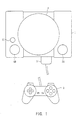
- Figs. 1, 2A, and 2B show an external structure of a video game machine as a whole.
- An operating device 2 is connected to the main body 1 of the game machine via a connector 3.
- the main body 1 of the game machine incorporates a CD-ROM drive for reproducing a CD-ROM.
- On the upper surface of the CD-ROM drive there provided a lid 4 of the CD-ROM drive, an open/close switch 5A for opening and closing the lid 4, a power source 5B, a reset 5C or the like.
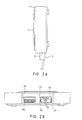
- the video game machine is constituted so that two operating devices 2 are connected to the main body 1 of the game machine respectively via a connector 3.
- connecting parts 6A and 6B are respectively arranged for use in the connector 3.
- connecting parts 7A and 7B are arranged adjacent to the connecting parts 6A and 6B.
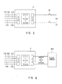
- the main body 1 of the game machine described herein is constituted as shown in Fig. 3.
- CPU 11, DRAM 12, MDEC 13, GPU (Graphic Processing Unit) 14 and the like are respectively connected to a system bus 10 comprising a 24-bit wide address and 32-bit wide data.
- the GTE (Geometric Transfer Engine) 15 is DMA connected to the CPU 11.
- the MDEC 13 is a processor for reproducing a motion picture, the processor developing a motion picture read from the CD-ROM. Further, the GTE 15 is a processor exclusively used with graphics. The processor comprises a plurality of computing parts which performs parallel processing. The processor performs parallel processing of coordinate transformation and rendering with respect to image data developed by the MDEC 13.
- the GPU 14 is a processor exclusively used with graphics like GTE 15. On the basis of data that has been coordinate transformed and computed at the GTE 15, the GPU 14 contributes to actual depiction of images such as shading, texture mapping, and raster processing.
- the resulting image data is sent to an expanding device 17 including an VDAC via a VRAM 16.
- the expanding device 17 expands the image data, and digital-to-analog converts the data, so that the resulting image signal is output as an RGB signal, and at the same time the resulting image signal is input to an NTSC encoder 18 to be output as an NTSC style video signal.
- an I/O bus 20 is formed comprising a 24-bit wide address and a 16-bit wide data.
- a ROM 21 storing a boot program and an extended I/O interface 22 are connected.
- a CD drive 23 is connected via a CD-DSP24 and a CD-ROM decoder 25.
- an SRAM 26 To this CD-ROM decoder 25, an SRAM 26, a mechanical controller 27 are connected to send decoded image data to the I/O bus 20 and to send sound data to an SPU (Sound Processing Unit) 28.
- the SPU 28 is a processor for sound process.
- the SPU 28 decodes the sound data decoded at the CD-ROM decoder 25 with the DRAM 29 connected so that the resulting sound data is D/A converted at a DAC 30 to be output as an audio output.
- the operating devices 2 and the recording device 8 are connected to a serial I/O interface (SIO) 31 connected to the peripheral 19.
- SIO serial I/O interface
- a plurality of operating devices 2 and a plurality of recording devices 8 are connected to the serial I/O interface 31 of the main body 1 of the game machine, so that data can be bidirectionally sent in accordance with a predetermined communication procedure.
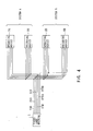
- the main body 1 of the game machine, operating devices 2A and 2B and recording devices 8A and 8B are connected as shown in Fig. 4.
- two systems A and B operating devices, that is, 2A and 2B, and recording devices 8A and 8B are connected to the main body 1 of the game machine.
- the main body 1 of the game machine is connected to the operating devices 2 and the recording devices 8 with a data transmission signal line TXD for sending data respectively to the operating devices 2 and the recording devices 8, a data transmission signal line RXD for sending data from the operating devices 2 and the recording devices 8 to the main body 1 of the game machine, a serial synchronization clock signal line SCK for extracting data from the data transmission signal lines RXD and TXD, and a control line DTR for establishing and interrupting communication by selecting two systems A and B, and a flow-control line DSR for transmitting a large size of data.
- a data transmission signal line TXD for sending data respectively to the operating devices 2 and the recording devices 8
- a data transmission signal line RXD for sending data from the operating devices 2 and the recording devices 8 to the main body 1 of the game machine
- a serial synchronization clock signal line SCK for extracting data from the data transmission signal lines RXD and TXD
- a control line DTR for establishing and interrupting communication by selecting two systems A
- data transmission signal lines TXD, RXD and a flow-control line DSR are connected in parallel from the main body 1 of the game machine to the operating devices 2A and 2B and the recording devices 8A and 8B respectively. Further, since the two systems A and B are connected to the control line DTR, a control line DTRA is connected to the operating device 2A and the recording device 8A of the system A from the main body 1 of the game machine while a control line DTRB is connected to the operating device 2B and the recording device 8B of the system B.
- the operating devices 2 incorporate a serial I/O interface (SIO) for serial communication with the main body 1 of the game machine and a parallel I/O interface (PIO) for inputting switch information.
- the operating devices 2 are composed of a one-chip microprocessor comprising a CPU, a RAM and a ROM, and a plurality of switches SW for inputting operation. This one-chip microprocessor controls the communication procedure.
- the recording devices 8 incorporates a serial I/O interface (SIO) for serial communication with the main body 1 of the game machine, and a parallel I/O interface (PIO) for inputting data into and outputting data from a memory MEM (for example composed of flash memory) in which data is to be actually memorized.
- SIO serial I/O interface
- PIO parallel I/O interface
- the recording devices 8 are composed of a one-chip microprocessor comprising a CPU, a RAM and a ROM, and a memory MEM. Also in the recording devices 8, the one-chip microprocessor controls the communication procedure.
- Figs. 7A and 7B show a communication procedure in which the main body 1 of the game machine communicates with operating devices 2A and 2B and recording devices 8A and 8B.
- Fig. 7A shows a procedure in which the main body 1 of the game machine communicates with the operating device 2A of the system A to incorporate, for example, operating data of the game.
- the main body 1 of the game machine outputs selection data to the control line DTRA at the outset.
- the operating device 2A and the recording device 8A of the system A are selected by the control line DTRA to produce a state of waiting for the succeeding receipt of TXD.
- the operating device 2B and the recording device 8B of the system B maintain a state of no response to the data sent through the data transmission signal line TXD because the control line DTRB does not change.
- the main body 1 of the game machine sends to the data transmission signal line TXD an identification code designating the operating device with one byte. This allows the operating device 2A and the recording device 8A of the system A to receive this identification code from the signal line TXD.
- the operating device 2A initiates communication with the main body 1 of the game machine thereafter as soon as the identification code designates the operating device.
- the recording device 8A assumes a state of no response to data sent through the data transmission signal line TXD as soon as the identification code designates the operating device.
- Fig. 7B shows a procedure in which the main body 1 of the game machine communicates with the recording device 8B of the system B to record, for example, game process data or the like into the recording device 8B.
- the main body 1 of the game machine outputs selection data to the control line DTRB at the outset.
- the operating device 2B and the recording device 8B of the system B are selected by the control line DTRB to produce a state of waiting for the succeeding receipt at the TXD.
- the operating device 2A and the recording device 8A of the system A maintain a state of no response to data sent through the data transmission signal line TXD because the control line DTRA does not change.
- the main body 1 of the game machine sends an identification code designating the recording device with 1 byte to the data transmission signal line TXD. This allows the operating device 2B and the recording device 8B of the system B to receive this identification code from the signal line TXD.
- the recording device 2B initiates communication with the main body 1 of the game machine thereafter as soon as the identification code designates the recording device.
- the operating device 2B assumes a state of no response to data successively sent through the data transmission signal line TXD as soon as the identification code designate the recording device.
- serial data communication is executed between the main body 1 of the game machine and the recording device 8B.
- This data communication between the main body 1 of the game machine and the recording device 8B also terminates when the main body 1 of the game machine outputs selection interruption data through the control line DTRB.
- a serial data communication is executed with a few signal lines and a simple signal connection between the main body 1 of the game machine, operating devices 2A and 2B and recording devices 8A and 8B of the two systems by executing communication procedure using a serial interface.
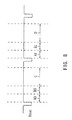
- the serial data communication between the main body 1 of the game machine, operating devices 2A and 2B, and recording devices 8A and 8B of the two systems is controlled, for example, in accordance with the screen rewriting timing as shown in Fig. 8.
- the main body 1 of the game machine normally communicates with the operating device 2A of the system A and the operating device 2B of the system B at timings A0 and B0 following the screen rewriting timing (in Fig. 8, a vertical synchronization signal V SYNC designates the screen rewriting timing) thereby respectively providing switch information such as switching operation or the like.
- the main body 1 of the game machine is connected to the operating devices 2A and 2B with a serial interface so that serial data is bidirectionally communicated in accordance with a predetermined communication procedure, while at the same time, the recording devices 8A and 8B are connected to the serial interface respectively corresponding to the operating devices 2A and 2B and the main body 1 of the game machine reads predetermined data from or writes it into the recording devices 8A and 8B in accordance with the communication procedure, thereby realizing the video game machine that can connect the main body 1 of the game machine thereof to the operating devices 2A and 2B and recording devices 8A and 8B with a simple structure to enable recording data during game operation.
- the recording devices can be connected to the video game machine with a simple connection with a few signal lines by connecting the recording devices 8A and 8B to a serial interface which connects the operating devices 2A and 2B to the main body 1 of the game machine. Further, since the number of connection line is small, and the connection line is independent of the signal line of the memory MEM used in the recording devices 8A and 8B, the recording devices 8A and 8B can be attached or detached when needed with the power source at the main body 1 of the game machine being turned on which leads to an improvement of the usage of the machine by users.
- the recording devices 8A and 8B with long communication data and the operating devices 2A and 2B with short communication data can occupy the serial interface so as to be efficiently used in communication for required time by rendering variable the length of communication data with each of the operating devices 2A and 2B, recording devices 8A and 8B and the main body 1 of the game machine simultaneously connected to each other.
- two operating devices are connected to the main body of the game machine, and two recording devices are connected to each other corresponding to respective operating devices.
- the number of the operating devices are not only limited to two, but three or more operating devices can be connected.
- the recording device can be connected corresponding to respective operating devices.
- a control line for selection for each of the system is provided as the communication procedure.
- the same advantage as that of the aforementioned embodiment can be realized when only corresponding operating device or recording device is allowed to communicate with the main body of the video game machine by adding peculiar identification code respectively to a plurality of operating devices and a plurality of recording devices as transmission data instead of using a control line in the aforementioned embodiment.
- the video game machine according to this invention is constituted, for example, as shown in Fig. 9.
- the video game machine provides a control system 50 composed of a central processing unit (CPU) 51 and a peripheral thereof, a graphic system 60 composed of a graphic processing unit (GPU) 62 for depicting images into a frame buffer 63, a sound system 70 composed of a sound processing unit (SPU) 71 or the like for generating music sounds, effect sounds or the like, an optical disk controller 80 for controlling the optical disks which constitute an auxiliary memory means, a communication controller 90 for controlling the input of an instruction from a controller for inputting an instruction from users and the input and output from the auxiliary memory for memorizing the setting of games or the like, and a bus 100 to which the control system 50 through the communication controller 90 are connected.
- a control system 50 composed of a central processing unit (CPU) 51 and a peripheral thereof
- a graphic system 60 composed of a graphic processing unit (GPU) 62 for depicting images into a frame buffer 63
- a sound system 70 composed of a sound processing unit (SPU) 71 or the like for generating
- the control system 50 provides a CPU 51, a peripheral device controller 52 for controlling an interruption and the transmission of a dynamic memory access (DMA), a main memory 53 comprising a random access memory (RAM), and a read only memory (ROM) 54 storing a program such as an operating system for controlling the main memory 53, the graphic system 60, the sound system 70 or the like.
- the CPU 51 controls the whole machine by executing the operating system memorized in the ROM 54.
- the CPU 51 comprises 32-bit long RISC CPU.
- the video game machine is constituted so that when the power is turned on, the CPU 51 in the control system 50 controls the graphic system 60, the sound system 70 or the like by executing the operating system stored in the ROM 54.
- the CPU 51 initializes the whole machine such as confirmation of the operation followed by controlling the optical disk controller 80 to execute the program such as games or the like stored in the optical disk.
- the CPU 51 controls the graphic system 60, the sound system 70 or the like in response to the input from users by executing the program such as games or the like to control the display of images, effect sounds, and the generation of music sounds.
- the graphic system 60 provides a geometry transfer engine (GTE) 61, a GPU 62 for depicting an image in accordance with an depiction instruction from the CPU 51, a frame buffer 63 for memorizing an image depicted by the GPU 62, and an image decoder 64 for decoding image data compressed and encoded by an orthogonal conversion such as discrete cosine conversion or the like.
- GTE geometry transfer engine
- GPU GPU
- frame buffer 63 for memorizing an image depicted by the GPU 62
- an image decoder 64 for decoding image data compressed and encoded by an orthogonal conversion such as discrete cosine conversion or the like.
- the GTE 61 provides a parallel arithmetic mechanism for executing a plurality of operations in parallel to execute coordinate conversion, light source calculation, matrix or vector calculations at high speed in response to an arithmetic request from the CPU 51.
- this GTE 61 is constituted so that coordinate calculation is performed with respect to a maximum of 1.5 million polygon per second in the case of flat shading for depicting, for example, a triangle-shaped polygon in the same color. This enables the video game machine to alleviate the load of the CPU 51 while performing a high-speed coordinate calculation.
- the GPU 62 depicts polygons or the like onto the frame buffer 63 in accordance with a depiction instruction from the CPU 51.
- This GPU 62 can depict about 0.36 million polygons at maximum per second.
- the frame buffer 63 comprises a dual port RAM.
- the frame buffer 63 is capable of depicting images from the GPU 62, transmitting data from the main memory, and reading data for the display at the same time.
- the frame buffer 63 has a capacity of 1M byte. Then the frame buffer is treated as a 16 bit-long 1024 (horizontal) x 512 (vertical) pixels matrix.
- this frame buffer 63 is provided with a CLUT area memorizing a color lock up table (CLUT) to which the GPU 62 refers to in depicting polygons or the like, and a texture area memorizing a material (texture) to be inserted (mapped) into polygons or the like depicted by the GPU 62 through coordinate conversion at the time of image depiction in addition to a display area to be output as a video output.
- CLUT color lock up table
- texture area memorizing a material (texture) to be inserted (mapped) into polygons or the like depicted by the GPU 62 through coordinate conversion at the time of image depiction in addition to a display area to be output as a video output.
- the CLUT area and the texture area is dynamically changed in accordance with the conversion of the display area.
- the GPU 62 is capable of glow shading for determining a color in the polygon with compensation from the color of the tip of the polygon, and texture mapping for sticking a texture memorized in the texture area onto the polygon in addition to the flat shading.
- the GTE 61 can calculate the coordinate of 0.5 million polygons at maximum per second.
- the image decoder 64 decodes an image data of a static image or a motion image stored in the main memory 53 by the control from the CPU 51 to memorize the image data in the main memory 53. Further, this reproduced image data can be memorized in the frame buffer 63 through the GPU 62 to be used as a background of the image depicted by the GPU 62.
- the sound system 70 provides an SPU 71 for generating music sounds, effect sounds or the like based on an instruction from the CPU 51, a sound buffer 72 in which waveform data or the like is recorded by the SPU 71, and a speaker 73 for outputting music sounds, effect sounds or the like generated by the SPU 71.
- the SPU 71 provides an ADPCM decoding function for reproducing sound data obtained by subjecting 16-bit long sound data to adaptive differential PCM as a 4-bit long differential signal, a reproduction function for generating effect sounds or the like by reproducing waveform data memorized in the sound buffer 72, and a modulation function or the like for modulating and reproducing waveform data memorized in the sound buffer 72.
- the sound system 70 can be used as sampling sound source for generating music sounds, effect sounds or the like based on waveform data memorized in the sound buffer 72 based on an instruction from the CPU 51.
- the optical disk controller 80 provides an optical disk device 81 for reproducing programs, data or the like recorded on optical disks, a decoder 82 for decoding, for example, program recorded with addition of error correction code (ECC), data or the like, and a buffer 83 for heightening the speed of the reading data from the optical disk by temporarily memorizing reproduced data from the optical disk device 81.
- ECC error correction code
- Sound data recorded on an optical disk reproduced by the optical disk device 81 includes PCM data obtained by analog-to-digital converting a sound signal in addition to the ADPCM data.
- Sound data recorded by representing a differential portion of, for example, 16-bit digital data with 4-bit as ADPCM data is decoded by a decoder 82 followed by being supplied to the SPU 71 and being subjected to digital-to-analog conversion or the like with the SPU 71. After that the sound data is used for driving the speaker 73.
- sound data recorded as, for example, 16-bit long digital data as PCM data is decoded by a decoder 82 followed by being used for driving the speaker 73.
- the communication controller 90 provides a communication controller 91 for controlling the communication with the CPU 51 via a bus 100, and a slot 93 to which the controller 92 is connected for inputting an instruction from users and two card connectors 95A and 95B to which two memory cards 94A and 94B are connected as external secondary memory means for secondarily memorizing set data of games or the like, are provided on the aforementioned communication controller 91.
- the controller 92 connected to the slot 93 has, for example, 16 instruction keys for inputting an instruction from users to transmit the state of this instruction key in accordance with an instruction from the communication controller 91 by synchronization communication to the communication controller 91 about sixty times per second. Then the communication controller 91 transmits the state of the instruction key at the controller 92 to the CPU 51.
- DMA transmission can be executed to enable direct data transmission between the main memory 53, the GPU 62, the image decoder 64, and the decoder 82 or the like by the control from the peripheral device controller 52 without the intervention of the CPU 51 as mentioned above. This allows alleviation of the load of the CPU 51 by data transmission to enable high speed data transmission.
- the CPU 51 transmits data to be memorized to the communication controller 91 when the set data or the like of the executed game needs to be memorized.
- the communication controller 91 memorizes data from the CPU 51 to the memory card 94A or the memory card 94B connected to the card connector 95A or the card connector slot.
- the communication controller 91 incorporates a protective circuit for preventing an electric breakage.
- the memory cards 94A and 94B are separated from the bus 100 so that they can be attached to and detached from the machine with the power on. Consequently, when the memory capacity is insufficient, a new memory card can be attached without shutting off the power source of the machine. Thus the game data that should be backed up will never be lost. A new memory card can be attached to write new data into a new memory card.
- each of the memory cards 94A and 94B comprises a flash memory MEM which can be accessed at random and which does not require a back up power source.
- each of the memory cards 94A and 94B incorporates a microcomputer MPU having a serial I/O interface (SIO) connected to control lines DTX and DTR through a card connector, data transmission signal lines RXD and TXD, and serial clocking signal line SCK, and a parallel I/O interface (PIO) connected to an address line (ADDRESS) of the flash memory MEM, data line (DATA), and control line (CONTROL).
- SIO serial I/O interface
- PIO parallel I/O interface
- the memory cards 94A and 94B are recognized as a file device identified as a double-digit hexadecimal number designating a port and a card connector from the application.
- each of this memory cards 94A and 94B is provided with an automatic initialization function at the time of the file opening. Then, in the microcomputer MPU, the memory cards 94A and 94B are connected to the card connector 95A or the card connector 95B so that the inside state is set to a state of no communication, at the time of the start of power supply from the machine, followed by accepting communication through the communication controller 91.
- the CPU 51 on the side of the machine tests the inside state of the microcomputer MPU incorporated in the memory cards 94A and 94B connected to the card connectors 95A and 95B, based on a field representing the inside state in a response packet for confirming a connection from the card to the host in the communication protocol, so that communication to the newly connected memory cards 94A and 94B is identified in the case of no communication in the microcomputer. And then, the structure of the file control data of the memory cards 94A and 95B newly connected, for example such as a file name, a file size, a slot number, a status or the like, is read.
- Such a communication protocol allows communication corresponding to the dynamic attachment and detachment of the memory cards 94A and 94B. This allows the two memory cards 94A and 94B to memorize the set state of the game or the like. In addition, the two memory cards 94A and 94B allow direct copying of data and each kind of data can be taken in from the two memory cards 94A and 94B to the machine at the same time.
- the CPU 51 on the side of the machine controls the data writing into a plurality of memory cards connected to the card connector 95A or the card connector 95B for example in accordance with a procedure shown in the flowchart of Fig. 10.
- an offset designating an order of memory cards is set to "0" at step SP1 followed by calculating the total number of memory cards required from the size of the data to be saved or the quantity of data at step SP2.
- step SP3 it is judged whether an unused memory card, or a memory card vacant in the total memory block is attached in the 0-th card slot assigned to the card connector 95A.
- the process proceeds to step SP4.
- the result is "YES”, or when an unused memory card is inserted into the 0-th card slot, the process proceeds to step SP6.
- step SP4 it is judged whether an unused memory card, or memory card vacant in the total memory block is inserted into the first card slot assigned to the card connector 95B. If the result of the judgment is "NO”, or no unused card is inserted into the first card slot, the process proceeds to step SP5. On the other hand, when the result is "YES”, or an unused memory card is inserted into the first card slot, the process proceeds to step SP7.
- step SP5 a message "insert an unused memory card” is displayed to notify users of the necessity of inserting the unused memory card into the 0-th or the first memory card slot, and the process returns to the step SP3.
- step SP6 the 0-th card slot in which the unused memory card is inserted is selected to designate it as a slot in which the data is to be written. Then the process proceeds to step SP8.
- the first card slot in which the unused memory card is inserted is selected to designate it as a slot in which data is to be written. Then, the process proceeds to step SP8. Then, at the step SP8, the name, the offset, and the total number of the cards are recorded on the head area of the file. This allows designation of a memory card in which data is written.
- step SP9 data is written, and the pointer on the main memory 53 is changed to the writing front.
- step SP10 offset is incremented.
- step SP11 judgment is made as to whether the all writing is completed or not. If the result of the judgment at step SP11 is "NO", or data to be written is present, the process returns to the step SP3, where data writing control continues. If the result of the judgment is "YES", or no data to be written is present, the data writing control is completed.
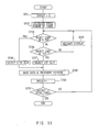
- the CPU 51 of the machine controls data reading from a plurality of memory cards connected to the card connector 95A or card connector 95B in accordance with a procedure shown in a flowchart in Fig. 11. Namely, when data is read which extends over a plurality of memory cards, the offset designating an order of the memory cards is set to "0" at the outset at step SP21. Then, at step SP22, the total number of memory card required is calculated from the size of the data to be loaded namely the data quantity.
- step SP23 judgement is made as to whether an object memory card is inserted into the 0-th card slot assigned to the card connector 95A in which file data to be loaded is written. If the result of the judgment at step SP23 is "NO", or no object memory card is inserted into the 0-th card slot, the process proceeds to step SP24. If the result of the judgment is "YES”, namely an object memory card is inserted into the 0-th card slot, the process returns to step SP16.
- step SP24 judgment is made as to whether an object memory card is inserted into the first card slot assigned to the card connector 95B in which file data to be loaded is written. If the result of the judgment at step SP24 is "NO", or no object memory card is inserted into the first card slot, the process proceeds to step SP25. If the result of the judgment is "YES”, or an object memory card is inserted into the first card slot, the process proceeds to step SP27.
- the result of the judgement at the step SP23 and SP24 is processed by detecting an agreement of offset recorded in the head area of the file. Then, at the step SP25, a message "insert a memory card with the offset number" is displayed to notify users of the necessity of inserting the object memory card into the 0-th or the first card slot. Then, the process returns to step SP23.
- the 0-th card slot is selected in which the object memory card is inserted to designate it as a slot in which data is read. Then the process proceeds to step SP28. Further, at the step S27, the first card slot is selected in which the object memory card is inserted to designate it as a slot in which data is read. Then, the process proceeds to step SP28.
- step SP28 data is read, the pointer on the main memory 53 is changed to the head of the next reading.
- step SP29 the offset is incremented.
- step SP30 judgment is made as to whether all the reading is completed. If the result of the judgment is "NO”, or data to be read is present, the process returns to the step SP23 to continue the control of data reading. On the other hand, the result of the judgment is "YES", or there is no data to be read, the control of data reading is completed.
- a plurality of card slots to which memory cards are connected as external secondary memory means are independently controlled by the host CPU 51 via the communication controller 91 connected to the main bus 100 to control the reading and/or writing of data extending over a plurality of memory cards, so that a plurality of small volume memory cards can be used as a large volume external secondary memory means, thereby enabling backing up game software or the like having a large data quantity extending over a plurality of memory cards.
- each of the memory cards 94A and 94B comprise a flash memory which can be accessed at random and which does not require a back-up power source, data can be stored semi-permanently.
- the video game machine provides a parallel input/output (I/O) port 101 connected to the bus 100 and a serial I/O port 102.
- I/O input/output
- the video game machine can be connected to the peripherals via the parallel I/O port 101, and the machine can communicate with other video game machines via the serial I/O port 102.
- embodiments of the invention provide a video game machine in which, for example, a game content stored in a CD-ROM is processed at operating devices while displaying the content on a display so as to perform the game.
Claims (2)
- Procédé pour écrire des données dans une console de jeu vidéo, la console de jeu vidéo comprenant :un appareil de reproduction de signal vidéo (50, 60) pour reproduire la vidéo à partir d'un support d'enregistrement vidéo (80), l'appareil de reproduction de signal vidéo ayant une unité de traitement centrale (51) et une mémoire principale (53), un accès de données dans la mémoire principale étant commandé par un pointeur de mémoire ;un ou plusieurs dispositifs de fonctionnement (92) chacun raccordé à l'appareil de reproduction de signal vidéo par un connecteur respectif d'une interface série pour communiquer de manière bi-directionnelle des données en série entre l'appareil de reproduction de signal vidéo et le dispositif de fonctionnement par une procédure de communication prédéterminée, l'appareil ayant au moins un 0ième et premier connecteurs, un jeu vidéo étant réalisé par le fonctionnement d'un ou plusieurs dispositifs de fonctionnement ; etun ou plusieurs moyens de mémoire (95A, 95B) chacun ayant une unité de traitement centrale, chaque moyen de mémoire étant raccordé à un connecteur d'interface série correspondant à un dispositif de fonctionnement respectif pour permettre à l'appareil de reproduction de signal vidéo d'écrire et/ou de lire des données se rapportant au jeu dans et/ou à partir du moyen de mémoire par la procédure de communication ;le procédé comprenant les étapes de :a) réglage (SP1) d'un décalage variable montrant l'ordre du moyen de mémoire à utiliser lorsque les données sont à écrire dans une pluralité de moyens de mémoire ;b) calcul (SP2) d'un nombre total nécessaire de moyens de mémoire pour une opération d'écriture de données actuelles à partir de la taille des données à écrire ;c) détection (SP3, SP4) si oui ou non un moyen de mémoire inutilisé, ayant tous ses blocs de mémoire vides, est raccordé au 0ième connecteur et, si non, si un moyen de mémoire inutilisé est raccordé au premier connecteur ;d) écriture (SP9) de données dans un moyen de mémoire inutilisé sous la forme d'un fichier ayant une zone de début de fichier enregistrant le nom, la variable de décalage, et le nombre de moyens total de mémoire utilisés pour l'opération d'écriture de données actuelle.e) changement (SP9) du pointeur de mémoire pour la mémoire principale à une position d'écriture suivante ;f) incrémentation (SP10) de la variable de décalage ; etg) détection (SP11) si oui ou non l'écriture de toutes les données est terminée et, si non, continuation de l'écriture des données dans un moyen de mémoire suivant à l'étape C.
- Procédé selon la revendication 1, dans lequel :
si à l'étape (c) on détecte qu'un moyen de mémoire inutilisé n'est pas raccordé au 0ième ou premier connecteur, un message notifiant à l'utilisateur de raccorder un moyen de mémoire inutilisé à un connecteur est affiché (SP5).
Applications Claiming Priority (4)
| Application Number | Priority Date | Filing Date | Title |
|---|---|---|---|
| JP14245494 | 1994-06-01 | ||
| JP14245494A JP3220328B2 (ja) | 1994-06-01 | 1994-06-01 | ビデオゲーム機 |
| JP142454/94 | 1994-06-01 | ||
| EP95303709A EP0685246B1 (fr) | 1994-06-01 | 1995-05-31 | Appareil de jeu vidéo avec dispositifs de mémoire externes |
Related Parent Applications (2)
| Application Number | Title | Priority Date | Filing Date |
|---|---|---|---|
| EP95303709A Division EP0685246B1 (fr) | 1994-06-01 | 1995-05-31 | Appareil de jeu vidéo avec dispositifs de mémoire externes |
| EP95303709.0 Division | 1995-05-31 |
Publications (3)
| Publication Number | Publication Date |
|---|---|
| EP0810015A2 EP0810015A2 (fr) | 1997-12-03 |
| EP0810015A3 EP0810015A3 (fr) | 1998-03-25 |
| EP0810015B1 true EP0810015B1 (fr) | 2001-08-22 |
Family
ID=15315695
Family Applications (4)
| Application Number | Title | Priority Date | Filing Date |
|---|---|---|---|
| EP01202281A Withdrawn EP1157722A1 (fr) | 1994-06-01 | 1995-05-31 | Appareil de reproduction de signal vidéo |
| EP97202438A Expired - Lifetime EP0810016B1 (fr) | 1994-06-01 | 1995-05-31 | Dispositif de jeu vidéo |
| EP95303709A Expired - Lifetime EP0685246B1 (fr) | 1994-06-01 | 1995-05-31 | Appareil de jeu vidéo avec dispositifs de mémoire externes |
| EP97202437A Expired - Lifetime EP0810015B1 (fr) | 1994-06-01 | 1995-05-31 | Dispositif de jeu vidéo |
Family Applications Before (3)
| Application Number | Title | Priority Date | Filing Date |
|---|---|---|---|
| EP01202281A Withdrawn EP1157722A1 (fr) | 1994-06-01 | 1995-05-31 | Appareil de reproduction de signal vidéo |
| EP97202438A Expired - Lifetime EP0810016B1 (fr) | 1994-06-01 | 1995-05-31 | Dispositif de jeu vidéo |
| EP95303709A Expired - Lifetime EP0685246B1 (fr) | 1994-06-01 | 1995-05-31 | Appareil de jeu vidéo avec dispositifs de mémoire externes |
Country Status (10)
| Country | Link |
|---|---|
| US (3) | US5791994A (fr) |
| EP (4) | EP1157722A1 (fr) |
| JP (1) | JP3220328B2 (fr) |
| KR (1) | KR100339948B1 (fr) |
| CN (1) | CN1103235C (fr) |
| AT (3) | ATE212245T1 (fr) |
| AU (1) | AU698045B2 (fr) |
| CA (1) | CA2150626A1 (fr) |
| DE (3) | DE69525180T2 (fr) |
| MY (1) | MY130592A (fr) |
Families Citing this family (77)
| Publication number | Priority date | Publication date | Assignee | Title |
|---|---|---|---|---|
| US7859551B2 (en) * | 1993-10-15 | 2010-12-28 | Bulman Richard L | Object customization and presentation system |
| TW353171B (en) * | 1995-05-10 | 1999-02-21 | Nintendo Co Ltd | Manipulator provided with an analog joy stick |
| US6241611B1 (en) | 1995-05-10 | 2001-06-05 | Nintendo Co., Ltd. | Function expansion device and operating device using the function expansion device |
| US7063615B2 (en) | 1995-06-29 | 2006-06-20 | Igt | Electronic gaming apparatus with authentication |
| US5643086A (en) | 1995-06-29 | 1997-07-01 | Silicon Gaming, Inc. | Electronic casino gaming apparatus with improved play capacity, authentication and security |
| USRE39369E1 (en) | 1995-06-29 | 2006-10-31 | Igt | Electronic casino gaming system with improved play capacity, authentication and security |
| JP3544268B2 (ja) | 1995-10-09 | 2004-07-21 | 任天堂株式会社 | 三次元画像処理装置およびそれを用いた画像処理方法 |
| US6007428A (en) | 1995-10-09 | 1999-12-28 | Nintendo Co., Ltd. | Operation controlling device and video processing system used therewith |
| JPH09167050A (ja) * | 1995-10-09 | 1997-06-24 | Nintendo Co Ltd | 操作装置およびそれを用いる画像処理システム |
| US6283857B1 (en) | 1996-09-24 | 2001-09-04 | Nintendo Co., Ltd. | Three-dimensional image processing apparatus with enhanced automatic and user point of view control |
| JP3524247B2 (ja) | 1995-10-09 | 2004-05-10 | 任天堂株式会社 | ゲーム機およびそれを用いたゲーム機システム |
| CN1149465C (zh) | 1995-10-09 | 2004-05-12 | 任天堂株式会社 | 三维图像显示游戏机系统和三维图像处理方法 |
| CN1109960C (zh) | 1995-11-10 | 2003-05-28 | 任天堂株式会社 | 万向操作杆装置 |
| US6155926A (en) | 1995-11-22 | 2000-12-05 | Nintendo Co., Ltd. | Video game system and method with enhanced three-dimensional character and background control |
| US6190257B1 (en) | 1995-11-22 | 2001-02-20 | Nintendo Co., Ltd. | Systems and method for providing security in a video game system |
| US6139433A (en) | 1995-11-22 | 2000-10-31 | Nintendo Co., Ltd. | Video game system and method with enhanced three-dimensional character and background control due to environmental conditions |
| US6267673B1 (en) | 1996-09-20 | 2001-07-31 | Nintendo Co., Ltd. | Video game system with state of next world dependent upon manner of entry from previous world via a portal |
| US6331856B1 (en) | 1995-11-22 | 2001-12-18 | Nintendo Co., Ltd. | Video game system with coprocessor providing high speed efficient 3D graphics and digital audio signal processing |
| US6022274A (en) * | 1995-11-22 | 2000-02-08 | Nintendo Co., Ltd. | Video game system using memory module |
| US6071191A (en) * | 1995-11-22 | 2000-06-06 | Nintendo Co., Ltd. | Systems and methods for providing security in a video game system |
| WO1997032248A1 (fr) * | 1996-02-29 | 1997-09-04 | Sony Computer Entertainment, Inc. | Processeur d'images et procede de traitement d'images |
| TW340927B (en) * | 1996-06-20 | 1998-09-21 | Sega Enterprises Kk | Peripheral, processor, game apparatus and game processing method |
| US6146277A (en) * | 1996-08-21 | 2000-11-14 | Konami Co., Ltd. | Command input method and recording medium |
| US6241610B1 (en) | 1996-09-20 | 2001-06-05 | Nintendo Co., Ltd. | Three-dimensional image processing system having dynamically changing character polygon number |
| US6139434A (en) * | 1996-09-24 | 2000-10-31 | Nintendo Co., Ltd. | Three-dimensional image processing apparatus with enhanced automatic and user point of view control |
| US6244959B1 (en) | 1996-09-24 | 2001-06-12 | Nintendo Co., Ltd. | Three-dimensional image processing system with enhanced character control |
| JPH10137445A (ja) * | 1996-11-07 | 1998-05-26 | Sega Enterp Ltd | ゲーム装置、画像音響処理装置および記録媒体 |
| JPH11188180A (ja) * | 1997-04-07 | 1999-07-13 | Snk:Kk | ゲームシステム |
| SG82658A1 (en) * | 1997-04-24 | 2001-08-21 | Sony Computer Entertainment Inc | Memory card device, video game apparatus, and program providing medium |
| US20020025852A1 (en) | 2000-09-29 | 2002-02-28 | Alcorn Allan E. | Gaming apparatus with portrait-mode display |
| US7243363B1 (en) * | 1997-07-10 | 2007-07-10 | Sony Computer Entertainment, Inc. | Entertainment system, picture display apparatus, information processing apparatus and synchronization control method |
| JP3655438B2 (ja) | 1997-07-17 | 2005-06-02 | 任天堂株式会社 | ビデオゲームシステム |
| KR100537880B1 (ko) * | 1997-08-08 | 2005-12-21 | 가부시키가이샤 세가 | 게임 장치 및 게임 시스템 |
| US6776717B2 (en) | 1997-08-24 | 2004-08-17 | Sony Computer Entertainment, Inc. | Game apparatus, game machine manipulation device, game system and interactive communication method for game apparatus |
| JPH1157212A (ja) * | 1997-08-24 | 1999-03-02 | Sony Computer Entertainment:Kk | ゲーム装置、ゲーム機用操作装置、ゲームシステム及びゲーム装置の双方向通信方法 |
| TW389918B (en) * | 1997-08-24 | 2000-05-11 | Sony Computer Entertainment Inc | Game apparatus, game machine manipulation device, game system and interactive communication method for game apparatus |
| JP4105788B2 (ja) | 1997-11-14 | 2008-06-25 | 任天堂株式会社 | ビデオゲーム装置およびその記憶媒体 |
| JP3103334B2 (ja) * | 1997-11-20 | 2000-10-30 | コナミ株式会社 | ビデオゲーム装置、ビデオゲームにおける制御方法及びビデオゲーム制御プログラムが記録された記録媒体 |
| JPH11309264A (ja) * | 1998-04-27 | 1999-11-09 | Aruze Corp | 遊技機内ユニット間信号伝送方式 |
| US6659860B1 (en) | 1998-05-12 | 2003-12-09 | Sony Computer Entertainment Inc. | Game device, game machine operation device and game system which employ a half-duplex serial communication system and game device two-way communication method |
| TW428408B (en) * | 1998-05-12 | 2001-04-01 | Sony Computer Entertainment Inc | Game apparatus, operation apparatus for game machines, and 2-way communication method for game systems and game apparatus |
| JP3566889B2 (ja) * | 1998-10-08 | 2004-09-15 | 株式会社ソニー・コンピュータエンタテインメント | 情報追加方法、ビデオゲーム機及び記録媒体 |
| JP2001038053A (ja) * | 1999-08-03 | 2001-02-13 | Konami Co Ltd | ゲーム展開の制御方法、ゲーム装置及び記録媒体 |
| JP2001046734A (ja) * | 1999-08-05 | 2001-02-20 | Konami Co Ltd | ゲーム展開の制御方法、ゲーム装置及び記録媒体 |
| JP2001058689A (ja) | 1999-08-25 | 2001-03-06 | Sony Computer Entertainment Inc | 記録媒体収容体および情報提供体 |
| JP2001079263A (ja) * | 1999-09-16 | 2001-03-27 | Sega Corp | ゲーム装置、データ処理方法、及び情報記録媒体 |
| US6866581B2 (en) | 1999-09-24 | 2005-03-15 | Igt | Video gaming apparatus for wagering with universal computerized controller and I/O interface for unique architecture |
| US6707457B1 (en) * | 1999-09-30 | 2004-03-16 | Conexant Systems, Inc. | Microprocessor extensions for two-dimensional graphics processing |
| US6717577B1 (en) | 1999-10-28 | 2004-04-06 | Nintendo Co., Ltd. | Vertex cache for 3D computer graphics |
| US6618048B1 (en) | 1999-10-28 | 2003-09-09 | Nintendo Co., Ltd. | 3D graphics rendering system for performing Z value clamping in near-Z range to maximize scene resolution of visually important Z components |
| JP3554281B2 (ja) * | 2000-02-10 | 2004-08-18 | 株式会社ソニー・コンピュータエンタテインメント | 記録媒体収容体および情報提供体 |
| US7988559B2 (en) | 2001-03-08 | 2011-08-02 | Igt | Computerized gaming system, method and apparatus |
| US7043641B1 (en) | 2000-03-08 | 2006-05-09 | Igt | Encryption in a secure computerized gaming system |
| CA2420290C (fr) | 2000-08-21 | 2009-04-21 | Igt | Procede et dispositif d'authentification de logiciel |
| US7196710B1 (en) | 2000-08-23 | 2007-03-27 | Nintendo Co., Ltd. | Method and apparatus for buffering graphics data in a graphics system |
| US6707458B1 (en) | 2000-08-23 | 2004-03-16 | Nintendo Co., Ltd. | Method and apparatus for texture tiling in a graphics system |
| US6700586B1 (en) | 2000-08-23 | 2004-03-02 | Nintendo Co., Ltd. | Low cost graphics with stitching processing hardware support for skeletal animation |
| US7576748B2 (en) | 2000-11-28 | 2009-08-18 | Nintendo Co. Ltd. | Graphics system with embedded frame butter having reconfigurable pixel formats |
| US6811489B1 (en) | 2000-08-23 | 2004-11-02 | Nintendo Co., Ltd. | Controller interface for a graphics system |
| US6636214B1 (en) | 2000-08-23 | 2003-10-21 | Nintendo Co., Ltd. | Method and apparatus for dynamically reconfiguring the order of hidden surface processing based on rendering mode |
| US7538772B1 (en) | 2000-08-23 | 2009-05-26 | Nintendo Co., Ltd. | Graphics processing system with enhanced memory controller |
| JP3506671B2 (ja) * | 2000-12-20 | 2004-03-15 | 株式会社インテリジェントシステムズ | 通信ゲームシステム |
| US7016496B2 (en) * | 2001-03-26 | 2006-03-21 | Sun Microsystems, Inc. | System and method for storing and accessing digital media content using smart card technology |
| US6850934B2 (en) | 2001-03-26 | 2005-02-01 | International Business Machines Corporation | Adaptive search engine query |
| US7162036B2 (en) | 2001-08-06 | 2007-01-09 | Igt | Digital identification of unique game characteristics |
| US6685567B2 (en) | 2001-08-08 | 2004-02-03 | Igt | Process verification |
| US6902481B2 (en) | 2001-09-28 | 2005-06-07 | Igt | Decoupling of the graphical presentation of a game from the presentation logic |
| US7931533B2 (en) | 2001-09-28 | 2011-04-26 | Igt | Game development architecture that decouples the game logic from the graphics logics |
| US8708828B2 (en) | 2001-09-28 | 2014-04-29 | Igt | Pluggable modular gaming modifiers and configuration templates for gaming environments |
| EP1463569A4 (fr) | 2001-11-26 | 2010-06-02 | Igt Reno Nev | Dispositif et procede de validation active d'interconnexion |
| US7864158B1 (en) | 2004-10-06 | 2011-01-04 | Mcgeever Daniel Robert | Use of graphical information to control processes |
| CN100354801C (zh) * | 2004-12-29 | 2007-12-12 | 大同股份有限公司 | 具有远端管理电子式计算机切换器的序列接口双向管理方法 |
| US8172684B2 (en) * | 2005-12-23 | 2012-05-08 | Wms Gaming Inc. | Networks for use in gaming |
| US8834277B2 (en) | 2012-12-27 | 2014-09-16 | Sony Computer Entertainment America Llc | Systems and methods for sharing cloud-executed mini-games, challenging friends and enabling crowd source rating |
| CN103902808B (zh) * | 2012-12-27 | 2017-04-26 | 索尼互动娱乐美国有限责任公司 | 用于生成和共享云供应游戏的视频剪辑的系统和方法 |
| US20180200621A1 (en) * | 2015-07-10 | 2018-07-19 | Cornell GOSS | Game Link Method |
| CN109289196A (zh) * | 2018-11-19 | 2019-02-01 | 杭州电魂网络科技股份有限公司 | 游戏存档处理方法及装置 |
Family Cites Families (21)
| Publication number | Priority date | Publication date | Assignee | Title |
|---|---|---|---|---|
| US4144583A (en) * | 1977-06-06 | 1979-03-13 | Digital Equipment Corporation | Secondary storage facility with means for monitoring error conditions |
| US4165072A (en) * | 1977-12-20 | 1979-08-21 | Atari, Inc. | Method of operating a video game |
| WO1984004834A1 (fr) * | 1983-05-31 | 1984-12-06 | Sega Electronics Inc | Systeme transportable de stockage a lecture/ecriture pour ordinateur domestique de jeux video |
| CA1330596C (fr) * | 1986-11-19 | 1994-07-05 | Yoshiaki Nakanishi | Cartouche de memoire et appareil de traitement de donnees |
| US4858930A (en) * | 1988-06-07 | 1989-08-22 | Namco, Ltd. | Game system |
| JP2677274B2 (ja) * | 1989-03-20 | 1997-11-17 | 富士通株式会社 | 可変長シリアルデータ通信方式 |
| JPH0380786U (fr) * | 1989-12-07 | 1991-08-19 | ||
| US5241663A (en) * | 1990-05-31 | 1993-08-31 | Sony Corporation | Hierarchically pairing memory blocks based upon relative storage capacities and simultaneously accessing each memory block within the paired memory blocks |
| JPH04176235A (ja) * | 1990-11-08 | 1992-06-23 | Nintendo Co Ltd | ゲーム機用通信アダプタ |
| US5317505A (en) * | 1990-12-19 | 1994-05-31 | Raznik Karabed | Game controller capable of storing and executing stored sequences of user playing button settings |
| GB2253325A (en) * | 1991-02-26 | 1992-09-02 | Gerald William Candy | Video graphics generator for an amusement machine |
| JPH06214670A (ja) * | 1991-04-29 | 1994-08-05 | Intel Corp | コンピュータ装置およびそれを初期化する方法 |
| US5333315A (en) * | 1991-06-27 | 1994-07-26 | Digital Equipment Corporation | System of device independent file directories using a tag between the directories and file descriptors that migrate with the files |
| JPH05135232A (ja) * | 1991-11-11 | 1993-06-01 | Seiko Epson Corp | ゲーム用icカード |
| US5267218A (en) * | 1992-03-31 | 1993-11-30 | Intel Corporation | Nonvolatile memory card with a single power supply input |
| GB9210786D0 (en) * | 1992-05-20 | 1992-07-08 | Codemasters Ltd | Memory cartridges |
| US5259626A (en) * | 1992-08-07 | 1993-11-09 | Std Electronic International Ltd. | Programmable video game controller |
| JPH06161368A (ja) * | 1992-11-19 | 1994-06-07 | Sony Corp | 画像作成装置 |
| US5591104A (en) * | 1993-01-27 | 1997-01-07 | Life Fitness | Physical exercise video system |
| EP0654289B1 (fr) * | 1993-04-09 | 2001-02-07 | Sega Enterprises, Ltd. | Multiconnecteur pour appareil de jeu |
| US5828862A (en) * | 1994-05-04 | 1998-10-27 | International Business Machines Corporation | Game programming flash memory cartridge system including a programmer and a reprogrammable cartridge |
-
1994
- 1994-06-01 JP JP14245494A patent/JP3220328B2/ja not_active Expired - Lifetime
-
1995
- 1995-05-31 AU AU20420/95A patent/AU698045B2/en not_active Ceased
- 1995-05-31 DE DE69525180T patent/DE69525180T2/de not_active Expired - Lifetime
- 1995-05-31 AT AT97202438T patent/ATE212245T1/de active
- 1995-05-31 AT AT95303709T patent/ATE179342T1/de active
- 1995-05-31 EP EP01202281A patent/EP1157722A1/fr not_active Withdrawn
- 1995-05-31 CA CA002150626A patent/CA2150626A1/fr not_active Abandoned
- 1995-05-31 DE DE69509297T patent/DE69509297T2/de not_active Expired - Lifetime
- 1995-05-31 US US08/454,837 patent/US5791994A/en not_active Expired - Lifetime
- 1995-05-31 EP EP97202438A patent/EP0810016B1/fr not_active Expired - Lifetime
- 1995-05-31 DE DE69522345T patent/DE69522345T2/de not_active Expired - Lifetime
- 1995-05-31 EP EP95303709A patent/EP0685246B1/fr not_active Expired - Lifetime
- 1995-05-31 EP EP97202437A patent/EP0810015B1/fr not_active Expired - Lifetime
- 1995-05-31 AT AT97202437T patent/ATE204498T1/de active
- 1995-06-01 KR KR1019950014812A patent/KR100339948B1/ko not_active IP Right Cessation
- 1995-06-01 CN CN95108529A patent/CN1103235C/zh not_active Expired - Lifetime
- 1995-06-01 MY MYPI95001439A patent/MY130592A/en unknown
-
1996
- 1996-11-12 US US08/747,538 patent/US6074300A/en not_active Expired - Lifetime
-
1997
- 1997-01-17 US US08/784,987 patent/US6030292A/en not_active Expired - Lifetime
Also Published As
| Publication number | Publication date |
|---|---|
| EP0685246A1 (fr) | 1995-12-06 |
| KR100339948B1 (ko) | 2002-12-06 |
| ATE179342T1 (de) | 1999-05-15 |
| EP0810016A3 (fr) | 1998-03-25 |
| ATE212245T1 (de) | 2002-02-15 |
| EP0685246B1 (fr) | 1999-04-28 |
| CA2150626A1 (fr) | 1995-12-02 |
| CN1115684A (zh) | 1996-01-31 |
| US6074300A (en) | 2000-06-13 |
| EP0810016A2 (fr) | 1997-12-03 |
| EP0810015A2 (fr) | 1997-12-03 |
| DE69525180T2 (de) | 2002-08-22 |
| DE69522345D1 (de) | 2001-09-27 |
| AU698045B2 (en) | 1998-10-22 |
| US5791994A (en) | 1998-08-11 |
| EP0810016B1 (fr) | 2002-01-23 |
| DE69509297D1 (de) | 1999-06-02 |
| KR960002025A (ko) | 1996-01-26 |
| CN1103235C (zh) | 2003-03-19 |
| EP1157722A1 (fr) | 2001-11-28 |
| ATE204498T1 (de) | 2001-09-15 |
| JP3220328B2 (ja) | 2001-10-22 |
| DE69525180D1 (de) | 2002-03-14 |
| MY130592A (en) | 2007-06-29 |
| DE69509297T2 (de) | 1999-11-04 |
| AU2042095A (en) | 1995-12-07 |
| US6030292A (en) | 2000-02-29 |
| DE69522345T2 (de) | 2002-06-13 |
| JPH07323158A (ja) | 1995-12-12 |
| EP0810015A3 (fr) | 1998-03-25 |
Similar Documents
| Publication | Publication Date | Title |
|---|---|---|
| EP0810015B1 (fr) | Dispositif de jeu vidéo | |
| US6674438B1 (en) | Method of and system for adding information and recording medium | |
| US6743103B2 (en) | Memory card device, video game apparatus, and program providing medium | |
| US8187099B2 (en) | Game method and apparatus for enabling a video game system console to execute video game programs originally written for execution on architecturally different video game platforms | |
| US6322450B1 (en) | Entertainment system with transferable calculator program | |
| AU713084B2 (en) | A method for writing data in a video game machine | |
| AU731237B2 (en) | A video gaming machine | |
| JP3198022B2 (ja) | ビデオゲーム装置 | |
| JPH117504A (ja) | メモリカード装置、ビデオゲーム装置 | |
| US6721264B1 (en) | Optical recording medium and entertainment system that employs it | |
| KR100557689B1 (ko) | 메모리카드장치,비디오게임장치및프로그램제공매체 | |
| JP3342866B2 (ja) | ビデオゲーム装置の外部2次記憶装置 | |
| JP2002078964A (ja) | エンタテインメント装置、コマンド入力受付方法およびコマンド表示方法 | |
| JP2001282466A (ja) | ビデオゲーム装置 | |
| MXPA99009178A (en) | Method of and system to add information and regis register | |
| MXPA99000021A (en) | Memory card device, video gate device and program providing medium | |
| MXPA00002991A (en) | Method of ink-jet recording with two fluids |
Legal Events
| Date | Code | Title | Description |
|---|---|---|---|
| PUAI | Public reference made under article 153(3) epc to a published international application that has entered the european phase |
Free format text: ORIGINAL CODE: 0009012 |
|
| AC | Divisional application: reference to earlier application |
Ref document number: 685246 Country of ref document: EP |
|
| AK | Designated contracting states |
Kind code of ref document: A2 Designated state(s): AT DE FR GB IT NL |
|
| PUAL | Search report despatched |
Free format text: ORIGINAL CODE: 0009013 |
|
| AK | Designated contracting states |
Kind code of ref document: A3 Designated state(s): AT DE FR GB IT NL |
|
| 17P | Request for examination filed |
Effective date: 19980811 |
|
| 17Q | First examination report despatched |
Effective date: 19991013 |
|
| GRAG | Despatch of communication of intention to grant |
Free format text: ORIGINAL CODE: EPIDOS AGRA |
|
| RAP1 | Party data changed (applicant data changed or rights of an application transferred) |
Owner name: SONY COMPUTER ENTERTAINMENT INC. |
|
| GRAG | Despatch of communication of intention to grant |
Free format text: ORIGINAL CODE: EPIDOS AGRA |
|
| GRAH | Despatch of communication of intention to grant a patent |
Free format text: ORIGINAL CODE: EPIDOS IGRA |
|
| GRAH | Despatch of communication of intention to grant a patent |
Free format text: ORIGINAL CODE: EPIDOS IGRA |
|
| GRAA | (expected) grant |
Free format text: ORIGINAL CODE: 0009210 |
|
| AC | Divisional application: reference to earlier application |
Ref document number: 685246 Country of ref document: EP |
|
| AK | Designated contracting states |
Kind code of ref document: B1 Designated state(s): AT DE FR GB IT NL |
|
| REF | Corresponds to: |
Ref document number: 204498 Country of ref document: AT Date of ref document: 20010915 Kind code of ref document: T |
|
| RIC1 | Information provided on ipc code assigned before grant |
Free format text: 7A 63F 13/00 A |
|
| REF | Corresponds to: |
Ref document number: 69522345 Country of ref document: DE Date of ref document: 20010927 |
|
| REG | Reference to a national code |
Ref country code: GB Ref legal event code: IF02 |
|
| ET | Fr: translation filed | ||
| PLBE | No opposition filed within time limit |
Free format text: ORIGINAL CODE: 0009261 |
|
| STAA | Information on the status of an ep patent application or granted ep patent |
Free format text: STATUS: NO OPPOSITION FILED WITHIN TIME LIMIT |
|
| 26N | No opposition filed | ||
| PGFP | Annual fee paid to national office [announced via postgrant information from national office to epo] |
Ref country code: AT Payment date: 20120426 Year of fee payment: 18 |
|
| PGFP | Annual fee paid to national office [announced via postgrant information from national office to epo] |
Ref country code: GB Payment date: 20130529 Year of fee payment: 19 Ref country code: DE Payment date: 20130529 Year of fee payment: 19 |
|
| PGFP | Annual fee paid to national office [announced via postgrant information from national office to epo] |
Ref country code: FR Payment date: 20130531 Year of fee payment: 19 Ref country code: NL Payment date: 20130516 Year of fee payment: 19 Ref country code: IT Payment date: 20130515 Year of fee payment: 19 |
|
| REG | Reference to a national code |
Ref country code: DE Ref legal event code: R119 Ref document number: 69522345 Country of ref document: DE |
|
| REG | Reference to a national code |
Ref country code: NL Ref legal event code: V1 Effective date: 20141201 |
|
| REG | Reference to a national code |
Ref country code: AT Ref legal event code: MM01 Ref document number: 204498 Country of ref document: AT Kind code of ref document: T Effective date: 20140531 |
|
| GBPC | Gb: european patent ceased through non-payment of renewal fee |
Effective date: 20140531 |
|
| REG | Reference to a national code |
Ref country code: DE Ref legal event code: R119 Ref document number: 69522345 Country of ref document: DE Effective date: 20141202 |
|
| PG25 | Lapsed in a contracting state [announced via postgrant information from national office to epo] |
Ref country code: AT Free format text: LAPSE BECAUSE OF NON-PAYMENT OF DUE FEES Effective date: 20140531 Ref country code: NL Free format text: LAPSE BECAUSE OF NON-PAYMENT OF DUE FEES Effective date: 20141201 |
|
| REG | Reference to a national code |
Ref country code: FR Ref legal event code: ST Effective date: 20150130 |
|
| PG25 | Lapsed in a contracting state [announced via postgrant information from national office to epo] |
Ref country code: DE Free format text: LAPSE BECAUSE OF NON-PAYMENT OF DUE FEES Effective date: 20141202 Ref country code: IT Free format text: LAPSE BECAUSE OF NON-PAYMENT OF DUE FEES Effective date: 20140531 |
|
| PG25 | Lapsed in a contracting state [announced via postgrant information from national office to epo] |
Ref country code: GB Free format text: LAPSE BECAUSE OF NON-PAYMENT OF DUE FEES Effective date: 20140531 Ref country code: FR Free format text: LAPSE BECAUSE OF NON-PAYMENT OF DUE FEES Effective date: 20140602 |