EP0809750B1 - Moteur a pistons alternatifs, notamment moteur a combustion interne, a equipage mobile hypocycloidal - Google Patents
Moteur a pistons alternatifs, notamment moteur a combustion interne, a equipage mobile hypocycloidal Download PDFInfo
- Publication number
- EP0809750B1 EP0809750B1 EP96904776A EP96904776A EP0809750B1 EP 0809750 B1 EP0809750 B1 EP 0809750B1 EP 96904776 A EP96904776 A EP 96904776A EP 96904776 A EP96904776 A EP 96904776A EP 0809750 B1 EP0809750 B1 EP 0809750B1
- Authority
- EP
- European Patent Office
- Prior art keywords
- reciprocating piston
- piston engine
- engine according
- rod
- portions
- Prior art date
- Legal status (The legal status is an assumption and is not a legal conclusion. Google has not performed a legal analysis and makes no representation as to the accuracy of the status listed.)
- Expired - Lifetime
Links
- 238000002485 combustion reaction Methods 0.000 title claims 2
- 230000008878 coupling Effects 0.000 claims description 5
- 238000010168 coupling process Methods 0.000 claims description 5
- 238000005859 coupling reaction Methods 0.000 claims description 5
- 229910000831 Steel Inorganic materials 0.000 claims description 4
- 239000002184 metal Substances 0.000 claims description 4
- 239000010959 steel Substances 0.000 claims description 4
- 239000013013 elastic material Substances 0.000 claims description 3
- 230000002093 peripheral effect Effects 0.000 claims description 3
- 230000000694 effects Effects 0.000 description 3
- 238000004519 manufacturing process Methods 0.000 description 3
- 230000000750 progressive effect Effects 0.000 description 3
- WYTGDNHDOZPMIW-RCBQFDQVSA-N alstonine Natural products C1=CC2=C3C=CC=CC3=NC2=C2N1C[C@H]1[C@H](C)OC=C(C(=O)OC)[C@H]1C2 WYTGDNHDOZPMIW-RCBQFDQVSA-N 0.000 description 2
- 230000000149 penetrating effect Effects 0.000 description 2
- 238000005452 bending Methods 0.000 description 1
- 238000010276 construction Methods 0.000 description 1
- 230000002349 favourable effect Effects 0.000 description 1
Images


Classifications
-
- F—MECHANICAL ENGINEERING; LIGHTING; HEATING; WEAPONS; BLASTING
- F02—COMBUSTION ENGINES; HOT-GAS OR COMBUSTION-PRODUCT ENGINE PLANTS
- F02B—INTERNAL-COMBUSTION PISTON ENGINES; COMBUSTION ENGINES IN GENERAL
- F02B75/00—Other engines
- F02B75/16—Engines characterised by number of cylinders, e.g. single-cylinder engines
- F02B75/18—Multi-cylinder engines
- F02B75/22—Multi-cylinder engines with cylinders in V, fan, or star arrangement
-
- F—MECHANICAL ENGINEERING; LIGHTING; HEATING; WEAPONS; BLASTING
- F01—MACHINES OR ENGINES IN GENERAL; ENGINE PLANTS IN GENERAL; STEAM ENGINES
- F01B—MACHINES OR ENGINES, IN GENERAL OR OF POSITIVE-DISPLACEMENT TYPE, e.g. STEAM ENGINES
- F01B9/00—Reciprocating-piston machines or engines characterised by connections between pistons and main shafts, not specific to groups F01B1/00 - F01B7/00
- F01B9/02—Reciprocating-piston machines or engines characterised by connections between pistons and main shafts, not specific to groups F01B1/00 - F01B7/00 with crankshaft
- F01B9/026—Rigid connections between piston and rod; Oscillating pistons
-
- F—MECHANICAL ENGINEERING; LIGHTING; HEATING; WEAPONS; BLASTING
- F02—COMBUSTION ENGINES; HOT-GAS OR COMBUSTION-PRODUCT ENGINE PLANTS
- F02B—INTERNAL-COMBUSTION PISTON ENGINES; COMBUSTION ENGINES IN GENERAL
- F02B75/00—Other engines
- F02B75/16—Engines characterised by number of cylinders, e.g. single-cylinder engines
- F02B75/18—Multi-cylinder engines
- F02B75/24—Multi-cylinder engines with cylinders arranged oppositely relative to main shaft and of "flat" type
- F02B75/246—Multi-cylinder engines with cylinders arranged oppositely relative to main shaft and of "flat" type with only one crankshaft of the "pancake" type, e.g. pairs of connecting rods attached to common crankshaft bearing
-
- F—MECHANICAL ENGINEERING; LIGHTING; HEATING; WEAPONS; BLASTING
- F16—ENGINEERING ELEMENTS AND UNITS; GENERAL MEASURES FOR PRODUCING AND MAINTAINING EFFECTIVE FUNCTIONING OF MACHINES OR INSTALLATIONS; THERMAL INSULATION IN GENERAL
- F16C—SHAFTS; FLEXIBLE SHAFTS; ELEMENTS OR CRANKSHAFT MECHANISMS; ROTARY BODIES OTHER THAN GEARING ELEMENTS; BEARINGS
- F16C7/00—Connecting-rods or like links pivoted at both ends; Construction of connecting-rod heads
- F16C7/02—Constructions of connecting-rods with constant length
- F16C7/023—Constructions of connecting-rods with constant length for piston engines, pumps or the like
-
- F—MECHANICAL ENGINEERING; LIGHTING; HEATING; WEAPONS; BLASTING
- F16—ENGINEERING ELEMENTS AND UNITS; GENERAL MEASURES FOR PRODUCING AND MAINTAINING EFFECTIVE FUNCTIONING OF MACHINES OR INSTALLATIONS; THERMAL INSULATION IN GENERAL
- F16C—SHAFTS; FLEXIBLE SHAFTS; ELEMENTS OR CRANKSHAFT MECHANISMS; ROTARY BODIES OTHER THAN GEARING ELEMENTS; BEARINGS
- F16C7/00—Connecting-rods or like links pivoted at both ends; Construction of connecting-rod heads
- F16C7/04—Connecting-rods or like links pivoted at both ends; Construction of connecting-rod heads with elastic intermediate part of fluid cushion
Definitions
- the invention is based on the preamble of the patent claim of US-A 2,271,766.
- a reciprocating piston machine with a hypocycloidal crank mechanism known, the one arranged at both ends with pistons in diametrically Cylinder connected push rod includes.
- This push rod consists of one mounted on a stroke eccentric of the hypocycloidal gear Main connecting rod for one of the pistons and one on the bearing cap of the main connecting rod hinged, shorter connecting rods for the other piston. Both pistons are also articulated to the respective connecting rod, so that it is known Push rod is kinkable and thus in particular the reduction of tolerance deviations stresses of moving components of the crank mechanism serves.
- a disadvantage of this known arrangement is that due to the unequal long connecting rods caused different piston wear.
- the invention has for its object a push rod with kinematic to show more favorable kinkability.
- the push rod according to the invention enables kinematically safe Support of the hypocycloid crank gear when passing through the Center position with the pistons in an OT / UT position in that the angular movements of the rod sections of the push rod which can be bent in the middle preferably are limited depending on progressively stiffening elasticities.
- the use of the articulated push rod designed according to the invention is further advantageous in a hypocycloid crank gear with Wattscher straight guidance. As is known, it moves to the axis of the opening in the bearing of the push rod coaxial center of the watt coupling instead of along an ideal straight guide line along a faintly serpentine guideline, the deviations of which from the ideal straight line using the articulated push rod in their effects are advantageously reduced.
- the embodiment of the invention comprises a push rod built from three parts with two push rod sections each connected to a piston, whose mutually facing end areas in a bearing opening for the hub-eccentric annular middle part is guided so that it can rotate are arranged.
- the push rod sections are advantageously on the central part attachable, so that in each cylinder the respective piston with the The push rod section on the cylinder head side can be mounted in a simple manner.
- the push rod sections according to the invention can be achieved a high degree of bending stiffness, taking the piston diameter into account as much as possible include spaced struts, on the one hand with a relatively short piston and on the other hand on the bearing side with a guide surface for the buckling movement having connecting bend are integrally connected. This configuration significantly simplifies the manufacture of each as a cast part Alloy-designed push rod sections.
- the middle part advantageously also made of steel.
- one is progressive with the degree of kinking of the push rod stiffening elasticity chosen, with the initially low elastic Resistance advantageous low piston side forces with angular movements of the Rod sections are achieved in the range of half the piston stroke, and the other strongly progressively increasing elastic resistance advantageous a clear Change of a straight guiding element of the hypocycloid crank gear from one guide side to the other with a piston top / bottom position Push rod causes.
- the progressively increasing resistance can also be selected in this way or be set so that at a predetermined maximum resistance value the effect of an attack results.
- This elastic angle stop is by means of coaxially penetrating Bolts on loaded bushings made of elastic material.
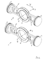
- a push rod 1 is equipped at both ends with pistons 2, 2 'for diametrically arranged cylinder of a hypocycloid crank gear equipped Reciprocating machine, not shown.
- the push rod 1 has one Crankshaft axis of rotation 3 parallel bearing opening 4 for rotating Image of a non-shown eccentric hub of the hypocycloid Crank gear on.
- the push rod 1 can be bent transversely to the stroke direction according to arrow "A" educated.
- the push rod 1 is out around the axis of rotation 3 of the crankshaft parallel axis 4 'of the bearing opening 4 arranged angularly movable Rod sections 5, 5 'formed, the angular movements of the rod sections 5, 5 'depending on the center of the push rod 1 permissible tilting movements of the respective rod sections 5, 5, firmly connected pistons 2, 2 'are achieved by means of elastic arrangements.
- the push rod 1 is made up of three parts educated.
- it comprises a separate the middle part 6 having the bearing opening 4.
- This middle part 6 is made of a collar bearing ring 7 and one in the free outer peripheral region of the bearing ring 7 'centered ring flange 8, the rod sections 5, 5' over in connection bends 9, 9 'arranged pressure-side guide surfaces 10, 10' with the The outer circumference of the bearing ring 7 'are connected.
- each of the guide surfaces 10, 12 or 10 'and 12 having connecting bends 9, 9' with two near the outer contour of the each piston 2, 2 'on its underside 16, 16' connecting in one piece Struts 17, 17 'is connected, each connecting bend 9, 9' one opposite the diameter of the respective piston 2, 2 'has a small chord dimension "h".
- This is the assembly of a respective piston 2, 2 'with a corresponding Rod section 5, 5 'ensured in a cylinder from the cylinder head side.
- FIG. 3 shows a central part 6 in which the collar bearing ring 7 and the ring flange 8 are one-piece design or one-piece design using fixed connections Form mounting part 18, the concentric stops 11 are substantially over the length of the tension-side guide surfaces 12 on the connection bends 9, 9 'extend. Collar 7 "and ring flange 8 are in the circumferential direction between the diametrical stops 11 corresponding to the strength or thickness of the connection bends 9, 9 'spaced apart in the axial direction.
- the multi-part construction of the push rod 1 according to the invention advantageously enables Way to achieve a small clearance in the bearing opening 4 to manufacture the middle part 6 from steel, whereas the pistons 2, 2 'with the associated rod sections 5, 5 'for reducing the mass of light metal are.
- the middle part 6 or the mounting part 18 can advantageously be manufactured as a pressed sheet metal part be, whereby guide surfaces are machined by grinding.
- both pistons 2, 2 ' connecting push rod with resiliently designed sections for central buckling should be provided.
Landscapes
- Engineering & Computer Science (AREA)
- General Engineering & Computer Science (AREA)
- Mechanical Engineering (AREA)
- Chemical & Material Sciences (AREA)
- Combustion & Propulsion (AREA)
- Shafts, Cranks, Connecting Bars, And Related Bearings (AREA)
- Transmission Devices (AREA)
- Pistons, Piston Rings, And Cylinders (AREA)
- Reciprocating Pumps (AREA)
Claims (13)
- Moteur à pistons alternatifs, notamment moteur à combustion interne à transmission de vilebrequin, hypocycloïdale, comprenantcaractérisé en ce queune bielle (1) dont les deux extrémités portent des pistons (2, 2') de cylindres diamétralement opposés,cette bielle ayant un passage de palier (4) parallèle à l'axe de rotation (3) du vilebrequin pour recevoir en rotation un excentrique de translation d'une transmission de vilebrequin, hypocycloïdale etcette bielle pouvant flamber transversalement à la direction de déplacement pour réduire des contraintes résultant de différences de tolérance dans le vilebrequin et dans le carter du moteur,la bielle (1) est formée par des segments de tiges (5, 5') mobiles angulairement autour de l'axe (4') du passage de palier (4) etles mouvements angulaires des segments de tiges (5, 5') sont obtenus en fonction des mouvements de basculement autorisés des pistons (2, 2') reliés solidairement aux segments d'axes (5, 5') respectifs, par des dispositions élastiques (15).
- Moteur à pistons alternatifs selon la revendication 1, caractérisé en ce quela bielle (1) comporte une partie centrale (6) particulière comportant un passage de palier (4) avecdes guides (10, 12, 10', 12) du côté de la traction et du côté de la pression, concentriques aux segments de tiges (5, 5') par rapport à l'axe (4') du passage de palier (4), ces guides pouvant être reliés de manière mobile angulairement avec des installations correspondantes de la partie centrale (6), etchaque segment de tige (5, 5') est limité angulairement de manière élastique par une butée élastique (15) par rapport à la partie centrale (6).
- Moteur à pistons alternatifs selon les revendications 1 et 2,
caractérisé en ce quela partie centrale (6) est formée d'un anneau de palier à collerettes (7) et d'une bride annulaire (8) de centrage dans la zone périphérique extérieure libre de l'anneau de palier (7'),les segments de tiges (5, 5') sont en liaison par des surfaces de guidage (10, 10'), du côté de la pression, avec la périphérie extérieure de l'anneau de palier (7') de la bague de palier composite (7) etla collerette (7") de l'anneau de palier à collerettes (7) et la bride annulaire (8), concentriquement à l'axe (3) du passage de palier (4), ont des butées (11) avec des surfaces de guidage (12) du côté de la traction pour les segments de tiges (5, 5'). - Moteur à pistons alternatifs selon les revendications 1 à 3,
caractérisé en ce quela bride annulaire (8) et la collerette (7") sont reliées en laissant subsister une mobilité angulaire pour les segments de tiges (5, 5') etdans ces segments, des vis (14) traversent les segments de tiges (5, 5') par des passages (13) etdans les passages (13) il y a des manchons (15) en matière élastique servant de butées d'angle élastiques. - Moteur à pistons alternatifs selon les revendications 1 à 4,
caractérisé en ce que
les vis sont des boulons (14). - Moteur à pistons alternatifs selon l'une des revendications 1 à 5,
caractérisé en ce queles segments de tiges (5, 5') comportent des surfaces de guidage (10, 12, 10', 12) chacune sur un arc de raccordement (9, 9'),cet arc étant relié à deux entretoises (17, 17') proches du contour extérieur du piston (2, 2') et qui rejoignent en une seule pièce son côté inférieur (16, 16'), etchaque arc de raccordement (9, 9') a une longueur de corde (h) inférieure au diamètre du piston (2, 2') respectif. - Moteur à pistons alternatifs selon l'une des revendications 1 à 6,
caractérisé en ce quela bague de palier à collerette (7) et la bride annulaire (8) constituent une pièce de montage (18) réalisée en une seule partie ou montée par des liaisons solidaires pour ne former qu'une seule partie etles butées concentriques (11) s'étendent essentiellement sur la longueur des surfaces de guidage (12), du côté de la traction, sur les arcs de raccordement (9, 9') etla collerette (7") et la surface annulaire (8) sont écartées dans la direction axiale, dans la direction périphérique, entre les butées diamétrales (11), en fonction de l'épaisseur des arcs de raccordement (9, 9'). - Moteur à pistons alternatifs selon les revendications 1 à 7,
caractérisé en ce quela partie centrale (6) ou la pièce de montage (18) sont en acier etles pistons (2, 2") et les segments de tiges correspondants (5, 5') sont en métal léger. - Moteur à pistons alternatifs selon l'une des revendications 1 à 8,
caractérisé en ce que
la pièce de montage (18) est une pièce en tôle pressée. - Moteur à pistons alternatifs selon l'une des revendications 1 à 9,
caractérisé en ce que,
les mouvements angulaires des segments de tiges (5, 5') de la bielle (1), flambant au milieu, sont limités en fonction de l'élasticité qui se durcit progressivement (15), et sert le cas échéant de butée. - Moteur à pistons alternatifs selon les revendications 1 à 10,
caractérisé parl'application de deux bielles (1) susceptibles de flamber au milieu pour deux paires de pistons entraínées dans le même sens par une transmission à vilebrequin, hypocycloïdale dans des cylindres diamétralement opposés, etla transmission à vilebrequin est équipée d'une installation de guidage rectiligne, réglable, placée entre les deux bielles (1). - Moteur à pistons alternatifs selon les revendications 1 à 11,
caractérisé en ce que
l'installation de guidage rectiligne est un bras de watt. - Moteur à pistons alternatifs selon la revendication 1,
caractérisé en ce qu'
une barre de poussée en une seule pièce du double piston comporte des segments réalisés avec une souplesse élastique.
Applications Claiming Priority (3)
| Application Number | Priority Date | Filing Date | Title |
|---|---|---|---|
| DE19504891 | 1995-02-14 | ||
| DE19504891A DE19504891A1 (de) | 1995-02-14 | 1995-02-14 | Hubkolbenmaschine, insbesondere Brennkraftmaschine mit hypozykloidischem Kurbelgetriebe |
| PCT/EP1996/000632 WO1996025588A1 (fr) | 1995-02-14 | 1996-02-14 | Moteur a pistons alternatifs, notamment moteur a combustion interne, a equipage mobile hypocycloidal |
Publications (2)
| Publication Number | Publication Date |
|---|---|
| EP0809750A1 EP0809750A1 (fr) | 1997-12-03 |
| EP0809750B1 true EP0809750B1 (fr) | 1999-04-07 |
Family
ID=7753921
Family Applications (1)
| Application Number | Title | Priority Date | Filing Date |
|---|---|---|---|
| EP96904776A Expired - Lifetime EP0809750B1 (fr) | 1995-02-14 | 1996-02-14 | Moteur a pistons alternatifs, notamment moteur a combustion interne, a equipage mobile hypocycloidal |
Country Status (8)
| Country | Link |
|---|---|
| US (1) | US5785029A (fr) |
| EP (1) | EP0809750B1 (fr) |
| JP (1) | JP2899419B2 (fr) |
| KR (1) | KR100266707B1 (fr) |
| CN (1) | CN1076074C (fr) |
| DE (2) | DE19504891A1 (fr) |
| ES (1) | ES2130802T3 (fr) |
| WO (1) | WO1996025588A1 (fr) |
Families Citing this family (10)
| Publication number | Priority date | Publication date | Assignee | Title |
|---|---|---|---|---|
| US6617422B1 (en) | 1997-05-23 | 2003-09-09 | Peter Nielsen | Peptide nucleic acid monomers and oligomers |
| WO2001059329A1 (fr) | 2000-02-08 | 2001-08-16 | Wiseman Technologies, Inc. | Moteur hypocycloide |
| KR100426085B1 (ko) * | 2001-10-25 | 2004-04-06 | 삼성광주전자 주식회사 | 밀폐형 왕복동식 압축기의 커넥팅로드 장치 |
| US6672263B2 (en) * | 2002-03-06 | 2004-01-06 | Tony Vallejos | Reciprocating and rotary internal combustion engine, compressor and pump |
| AUPS204302A0 (en) * | 2002-04-30 | 2002-06-06 | Cmc Power Systems Limited | A connection assembly |
| US7219647B1 (en) | 2005-12-16 | 2007-05-22 | Michael Dennis Brickley | Force transfer mechanism for an engine |
| CN101975110A (zh) * | 2010-10-08 | 2011-02-16 | 舒锦海 | 齿轮传动(opoc)内燃机 |
| US8763583B2 (en) * | 2011-02-11 | 2014-07-01 | Ecomotors, Inc. | Opposed-piston, opposed-cylinder engine with collinear cylinders |
| CN102182556A (zh) * | 2011-03-10 | 2011-09-14 | 舒锦海 | 对撞齿轮内燃机 |
| CN105370398B (zh) * | 2015-10-13 | 2018-09-04 | 安徽中鼎动力有限公司 | 水平对置活塞对置气缸发动机共轴轴承 |
Family Cites Families (18)
| Publication number | Priority date | Publication date | Assignee | Title |
|---|---|---|---|---|
| DD11025A (fr) * | ||||
| FR801290A (fr) * | 1935-01-23 | 1936-07-31 | Williams Rotary Engines Compan | Mécanisme pour transformer un mouvement rectiligne alternatif en un mouvement rotatoire continu |
| US2271766A (en) * | 1940-05-06 | 1942-02-03 | Harry A Huebotter | Engine |
| CH229679A (de) * | 1941-11-12 | 1943-11-15 | Ag Scintilla | Kurbelantrieb ohne Totpunkte. |
| DE1403962A1 (de) * | 1963-03-14 | 1969-01-30 | Bosch Gmbh Robert | Zweizylinderverdichter,insbesondere fuer Kaeltemaschinen |
| US3386429A (en) * | 1966-07-11 | 1968-06-04 | Earl M. Trammell Jr. | Internal combustion engine |
| GB1388111A (en) * | 1971-04-07 | 1975-03-19 | Exxon Research Engineering Co | Engines motors pumps and compressors |
| DE8233321U1 (de) * | 1982-11-26 | 1988-08-25 | MTU Motoren- und Turbinen-Union München GmbH, 8000 München | Kolben-Pleuel-Lageranordnung |
| US4498372A (en) * | 1983-12-23 | 1985-02-12 | Lear Siegler, Inc. | Pump with ring retained floating wrist pins and connecting rods |
| GB8503535D0 (en) * | 1985-02-12 | 1985-03-13 | Secretary Trade Ind Brit | Fibre reinforced plastics connecting rod |
| US4727794A (en) * | 1987-01-20 | 1988-03-01 | Kmicikiewicz Marek A | Radial engine |
| BR8707047A (pt) * | 1987-12-17 | 1989-07-18 | Brasil Compressores Sa | Aperfeicoamento em compressor de pistao alternativo para pequenas maquinas de refrigeracao e seu processo de montagem |
| DE3919609C2 (de) * | 1989-06-15 | 1998-02-05 | Ppv Verwaltungs Ag | Kurbeltrieb für eine Kolbenmaschine |
| DE4020826A1 (de) * | 1990-06-29 | 1992-01-09 | Michael Zoche | Verbrennungsmotor |
| DE4139716A1 (de) * | 1991-12-02 | 1993-06-03 | Bayerische Motoren Werke Ag | Hubkolbenmaschine, insbesondere brennkraftmaschine, mit hypozykloidischem kurbelgetriebe |
| DE4205283C2 (de) * | 1992-02-21 | 2000-07-27 | Bayerische Motoren Werke Ag | Hubkolbenmaschine mit hypozykloidischem Kurbelgetriebe, insbesondere Brennkraftmaschine |
| US5560327A (en) * | 1993-11-08 | 1996-10-01 | Brackett; Douglas C. | Internal combustion engine with improved cycle dynamics |
| US5673666A (en) * | 1995-10-17 | 1997-10-07 | General Motors Corporation | Connecting rod for internal combustion engine |
-
1995
- 1995-02-14 DE DE19504891A patent/DE19504891A1/de not_active Withdrawn
-
1996
- 1996-02-14 DE DE59601613T patent/DE59601613D1/de not_active Expired - Fee Related
- 1996-02-14 ES ES96904776T patent/ES2130802T3/es not_active Expired - Lifetime
- 1996-02-14 KR KR1019970705248A patent/KR100266707B1/ko not_active Expired - Fee Related
- 1996-02-14 EP EP96904776A patent/EP0809750B1/fr not_active Expired - Lifetime
- 1996-02-14 JP JP8524663A patent/JP2899419B2/ja not_active Expired - Fee Related
- 1996-02-14 CN CN96191924A patent/CN1076074C/zh not_active Expired - Fee Related
- 1996-02-14 WO PCT/EP1996/000632 patent/WO1996025588A1/fr not_active Ceased
- 1996-02-14 US US08/894,210 patent/US5785029A/en not_active Expired - Fee Related
Also Published As
| Publication number | Publication date |
|---|---|
| WO1996025588A1 (fr) | 1996-08-22 |
| EP0809750A1 (fr) | 1997-12-03 |
| JPH10510348A (ja) | 1998-10-06 |
| DE19504891A1 (de) | 1996-08-22 |
| US5785029A (en) | 1998-07-28 |
| DE59601613D1 (de) | 1999-05-12 |
| ES2130802T3 (es) | 1999-07-01 |
| KR19980701851A (ko) | 1998-06-25 |
| CN1076074C (zh) | 2001-12-12 |
| CN1174589A (zh) | 1998-02-25 |
| JP2899419B2 (ja) | 1999-06-02 |
| KR100266707B1 (ko) | 2000-09-15 |
Similar Documents
| Publication | Publication Date | Title |
|---|---|---|
| DE3324634C2 (fr) | ||
| DE69605461T2 (de) | Spiralvakuumpumpe | |
| EP0289697B1 (fr) | Dispositif de commande d'aubes de guidage à calage variable pour turbomachine axiale | |
| EP0809750B1 (fr) | Moteur a pistons alternatifs, notamment moteur a combustion interne, a equipage mobile hypocycloidal | |
| DE2521312B1 (de) | Schraegscheiben-schwenklager fuer eine hydraulische axialkolbenmaschine | |
| DE19961788B4 (de) | Zweistufige Planetengetriebeanordnung mit kleinem Spiel | |
| DE2920081C2 (de) | Brennkraftmaschine, dessen Triebwerksträger über kraftübertragende und körperschallisolierende Elemente am Kurbelgehäuse abgestützt ist | |
| EP3077135B1 (fr) | Machine-outil pouvant être entraînée en oscillation | |
| DE102009043505A1 (de) | Verbrennungskraftmaschine mit variabler Verdichtung | |
| DE1403961A1 (de) | Pleuel fuer eine Kolbenmaschine | |
| DE69623163T2 (de) | Drehantrieb | |
| DE102004041769B4 (de) | Nockenwellenversteller | |
| DE29714516U1 (de) | Vorrichtung zur Umsetzung einer reversierenden Linearbewegung | |
| EP0392063A1 (fr) | Manivelle à suppression de point mort | |
| DE3148027C2 (de) | Taumelscheiben-Brennkraftmaschine | |
| DE102008019072B3 (de) | Kurvengetriebe, insbesondere für eine Kolbenpumpe für die Hochleistungsflüssigkeitschromatographie | |
| DE102020203621A1 (de) | Kippsegmentlager | |
| DE3327977C1 (de) | Vorrichtung zum Ausrücken einer Kupplung | |
| DE102023134170B4 (de) | Lenkgetriebe | |
| DE102014102131A1 (de) | Oszillierend antreibbare Werkzeugmaschine | |
| DE202011002132U1 (de) | Getriebeexzenter | |
| DE19528267C2 (de) | Verstellvorrichtung für Laufradschaufeln einer Kaplan-Turbine | |
| DE2948801C2 (de) | Gepanzerte Gelenkschutzhülle für Drehgelenkkupplungen | |
| EP1230483A1 (fr) | Moteur a pistons, en particulier compresseur | |
| EP3418533B1 (fr) | Bielle pour un moteur à combustion interne à compression variable |
Legal Events
| Date | Code | Title | Description |
|---|---|---|---|
| PUAI | Public reference made under article 153(3) epc to a published international application that has entered the european phase |
Free format text: ORIGINAL CODE: 0009012 |
|
| AK | Designated contracting states |
Kind code of ref document: A1 Designated state(s): DE ES FR GB IT |
|
| 17P | Request for examination filed |
Effective date: 19970701 |
|
| GRAG | Despatch of communication of intention to grant |
Free format text: ORIGINAL CODE: EPIDOS AGRA |
|
| 17Q | First examination report despatched |
Effective date: 19980525 |
|
| GRAG | Despatch of communication of intention to grant |
Free format text: ORIGINAL CODE: EPIDOS AGRA |
|
| GRAH | Despatch of communication of intention to grant a patent |
Free format text: ORIGINAL CODE: EPIDOS IGRA |
|
| GRAH | Despatch of communication of intention to grant a patent |
Free format text: ORIGINAL CODE: EPIDOS IGRA |
|
| GRAA | (expected) grant |
Free format text: ORIGINAL CODE: 0009210 |
|
| AK | Designated contracting states |
Kind code of ref document: B1 Designated state(s): DE ES FR GB IT |
|
| GBT | Gb: translation of ep patent filed (gb section 77(6)(a)/1977) |
Effective date: 19990408 |
|
| REF | Corresponds to: |
Ref document number: 59601613 Country of ref document: DE Date of ref document: 19990512 |
|
| REG | Reference to a national code |
Ref country code: ES Ref legal event code: FG2A Ref document number: 2130802 Country of ref document: ES Kind code of ref document: T3 |
|
| ET | Fr: translation filed | ||
| PLBE | No opposition filed within time limit |
Free format text: ORIGINAL CODE: 0009261 |
|
| STAA | Information on the status of an ep patent application or granted ep patent |
Free format text: STATUS: NO OPPOSITION FILED WITHIN TIME LIMIT |
|
| 26N | No opposition filed | ||
| REG | Reference to a national code |
Ref country code: GB Ref legal event code: IF02 |
|
| PGFP | Annual fee paid to national office [announced via postgrant information from national office to epo] |
Ref country code: ES Payment date: 20050127 Year of fee payment: 10 |
|
| PGFP | Annual fee paid to national office [announced via postgrant information from national office to epo] |
Ref country code: GB Payment date: 20050210 Year of fee payment: 10 |
|
| PGFP | Annual fee paid to national office [announced via postgrant information from national office to epo] |
Ref country code: FR Payment date: 20050228 Year of fee payment: 10 |
|
| PGFP | Annual fee paid to national office [announced via postgrant information from national office to epo] |
Ref country code: DE Payment date: 20050323 Year of fee payment: 10 |
|
| PG25 | Lapsed in a contracting state [announced via postgrant information from national office to epo] |
Ref country code: GB Free format text: LAPSE BECAUSE OF NON-PAYMENT OF DUE FEES Effective date: 20060214 |
|
| PG25 | Lapsed in a contracting state [announced via postgrant information from national office to epo] |
Ref country code: ES Free format text: LAPSE BECAUSE OF NON-PAYMENT OF DUE FEES Effective date: 20060215 |
|
| PGFP | Annual fee paid to national office [announced via postgrant information from national office to epo] |
Ref country code: IT Payment date: 20060228 Year of fee payment: 11 |
|
| PG25 | Lapsed in a contracting state [announced via postgrant information from national office to epo] |
Ref country code: DE Free format text: LAPSE BECAUSE OF NON-PAYMENT OF DUE FEES Effective date: 20060901 |
|
| GBPC | Gb: european patent ceased through non-payment of renewal fee |
Effective date: 20060214 |
|
| REG | Reference to a national code |
Ref country code: FR Ref legal event code: ST Effective date: 20061031 |
|
| REG | Reference to a national code |
Ref country code: ES Ref legal event code: FD2A Effective date: 20060215 |
|
| PG25 | Lapsed in a contracting state [announced via postgrant information from national office to epo] |
Ref country code: FR Free format text: LAPSE BECAUSE OF NON-PAYMENT OF DUE FEES Effective date: 20060228 |
|
| PG25 | Lapsed in a contracting state [announced via postgrant information from national office to epo] |
Ref country code: IT Free format text: LAPSE BECAUSE OF NON-PAYMENT OF DUE FEES Effective date: 20070214 |