EP0807980B1 - Photovoltaische Anordnung und Herstellungsverfahren - Google Patents
Photovoltaische Anordnung und Herstellungsverfahren Download PDFInfo
- Publication number
- EP0807980B1 EP0807980B1 EP97108076A EP97108076A EP0807980B1 EP 0807980 B1 EP0807980 B1 EP 0807980B1 EP 97108076 A EP97108076 A EP 97108076A EP 97108076 A EP97108076 A EP 97108076A EP 0807980 B1 EP0807980 B1 EP 0807980B1
- Authority
- EP
- European Patent Office
- Prior art keywords
- adhesive
- electrically conductive
- photovoltaic device
- metallic wire
- bus bar
- Prior art date
- Legal status (The legal status is an assumption and is not a legal conclusion. Google has not performed a legal analysis and makes no representation as to the accuracy of the status listed.)
- Expired - Lifetime
Links
Images


Classifications
-
- H—ELECTRICITY
- H10—SEMICONDUCTOR DEVICES; ELECTRIC SOLID-STATE DEVICES NOT OTHERWISE PROVIDED FOR
- H10F—INORGANIC SEMICONDUCTOR DEVICES SENSITIVE TO INFRARED RADIATION, LIGHT, ELECTROMAGNETIC RADIATION OF SHORTER WAVELENGTH OR CORPUSCULAR RADIATION
- H10F77/00—Constructional details of devices covered by this subclass
- H10F77/20—Electrodes
- H10F77/244—Electrodes made of transparent conductive layers, e.g. transparent conductive oxide [TCO] layers
-
- H—ELECTRICITY
- H10—SEMICONDUCTOR DEVICES; ELECTRIC SOLID-STATE DEVICES NOT OTHERWISE PROVIDED FOR
- H10F—INORGANIC SEMICONDUCTOR DEVICES SENSITIVE TO INFRARED RADIATION, LIGHT, ELECTROMAGNETIC RADIATION OF SHORTER WAVELENGTH OR CORPUSCULAR RADIATION
- H10F19/00—Integrated devices, or assemblies of multiple devices, comprising at least one photovoltaic cell covered by group H10F10/00, e.g. photovoltaic modules
- H10F19/80—Encapsulations or containers for integrated devices, or assemblies of multiple devices, having photovoltaic cells
-
- H—ELECTRICITY
- H10—SEMICONDUCTOR DEVICES; ELECTRIC SOLID-STATE DEVICES NOT OTHERWISE PROVIDED FOR
- H10F—INORGANIC SEMICONDUCTOR DEVICES SENSITIVE TO INFRARED RADIATION, LIGHT, ELECTROMAGNETIC RADIATION OF SHORTER WAVELENGTH OR CORPUSCULAR RADIATION
- H10F71/00—Manufacture or treatment of devices covered by this subclass
-
- H—ELECTRICITY
- H10—SEMICONDUCTOR DEVICES; ELECTRIC SOLID-STATE DEVICES NOT OTHERWISE PROVIDED FOR
- H10F—INORGANIC SEMICONDUCTOR DEVICES SENSITIVE TO INFRARED RADIATION, LIGHT, ELECTROMAGNETIC RADIATION OF SHORTER WAVELENGTH OR CORPUSCULAR RADIATION
- H10F77/00—Constructional details of devices covered by this subclass
- H10F77/20—Electrodes
- H10F77/206—Electrodes for devices having potential barriers
- H10F77/211—Electrodes for devices having potential barriers for photovoltaic cells
-
- Y—GENERAL TAGGING OF NEW TECHNOLOGICAL DEVELOPMENTS; GENERAL TAGGING OF CROSS-SECTIONAL TECHNOLOGIES SPANNING OVER SEVERAL SECTIONS OF THE IPC; TECHNICAL SUBJECTS COVERED BY FORMER USPC CROSS-REFERENCE ART COLLECTIONS [XRACs] AND DIGESTS
- Y02—TECHNOLOGIES OR APPLICATIONS FOR MITIGATION OR ADAPTATION AGAINST CLIMATE CHANGE
- Y02E—REDUCTION OF GREENHOUSE GAS [GHG] EMISSIONS, RELATED TO ENERGY GENERATION, TRANSMISSION OR DISTRIBUTION
- Y02E10/00—Energy generation through renewable energy sources
- Y02E10/50—Photovoltaic [PV] energy
Definitions
- the present invention relates to a photovoltaic device having a highly reliable electrode structure and a process for producing said photovoltaic device. More particularly, the present invention relates to a photovoltaic device having a collecting electrode comprising a metallic wire and a bus bar and having an improved connection structure with respect to said metallic wire and bus bar.
- U.S. Patent No. 4,260,429 discloses that as the collecting electrode disposed on the front surface of a solar cell, a plurality of metallic wires coated by a polymer material containing electrically conductive particles are fixed on the front surface of the solar cell by way of heat or/and pressure and a common bus bar is connected to end portions of the metallic wires.
- U.S. Patent No. 5,084,107 discloses a manner of providing a plurality of metallic wires having opposite end portions supported by clamps, applying an electrically conductive adhesive onto at least partial portions of the metallic wires, subjecting the metallic wires applied with the electrically conductive adhesive to heat treatment while pressing the metallic wires onto the front surface of a solar cell whereby solidifying the electrically conductive adhesive, and cutting the metallic wires, whereby collecting electrodes are formed on the front surface of the solar cell.
- a collection electrode for collecting electric currents of the metallic wires is connected to the metallic wires.
- Document EP-A-0 684 652 discloses a photovoltaic device which comprises at least a metal wire on a face of a photovoltaic element for collecting the power generated by the photovoltaic element.
- the metal wire is coated with an electroconductive adhesive over the entire length of the metal wire and fixed onto the photovoltaic element.
- the fixing may be provided by contacting said wire via a copper foil and an adhesive tape to an insulation tape, which is provided on the surface of a photovoltaic element.
- An object of the present invention is to eliminate the foregoing problems in the prior art and to provide a highly reliable electrode structure for a photovoltaic device, which can be efficiently formed at an adequate working effeciency.
- a typical embodiment of the electrode structure according to the present invention comprises a power generation region having a metallic wire as a collecting electrode arranged over a transparent and electrically conductive electrode layer for a photovoltaic element and a fixing region of fixing opposite end portions of said metallic wire, wherein said metallic wire is fixed to a heat resistant polymer film through an adhesive material, and said metallic wire is positioned between a bus bar and said adhesive material while electrically connecting with said bus bar.
- Another object of the present invention is to provide an improved photovoltaic device provided with said electrode structure, which exhibits satisfactory photovoltaic characteristics.
- a further object of the present invention is to provide a process which enables one to efficiently produce said photovoltaic device at a high yield.
- the present invention provides an improved photovoltaic device provided with a highly reliable electrode structure and a process for producing said photovoltaic device.
- the photovoltaic device includes a photovoltaic element comprising a substrate having an electrically conductive surface, a semiconductor layer formed on said electrically conductive surface of said substrate, and a transparent and electrically conductive electrode layer formed on said semiconductor layer; a power generation region having a metallic wire arranged over said transparent and electrically conductive electrode layer of said photovoltaic element; and a fixing region of fixing an end portion of said metallic wire, wherein said end portion of said metallic wire is fixed to a bus bar in said fixing region by an adhesive body in said fixing region wherein in said adhesive body a polymer film is sandwiched between two adhesive material layers and wherein said end portion of said metallic wire is positioned between said bus bar and said adhesive body in said fixing region while electrically connecting with said bus bar such that said end portion of said metallic wire is embedded by said adhesive body and the bus bar is also fixed to said photovoltaic element by said adhesive body.
- the process according to the present invention is a process for producing a said afore mentioned photovoltaic device, characterized by comprising the steps of:
- the photovoltaic device provided with the specific electrode structure according to the present invention has various advantages as will be described below.
- the process for the production of a photovoltaic device according to the present invention enables to efficiently produce a highly reliable photovoltaic device at an improved yield by a simple production process with a diminished number of steps.
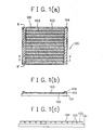
- FIG. 1(a) is a schematic plan view illustrating an example of a photovoltaic device according to the present invention.
- FIG. 1(b) is a schematic cross-sectional view, taken along the line A-A' in FIG. 1(a).
- FIG. 1(c) is a schematic cross-sectional view, taken along the line B-B' in FIG. 1(a).
- reference numeral 100 indicates a photovoltaic device, reference numeral 101 a substrate at least having an electrically conductive surface, reference numeral 102 a photovoltaic element comprising a lower electrode layer and a photoelectric conversion semiconductor layer and a transparent and electrically conductive layer (these layers are not shown), reference numeral 103 a metallic wire as a first collecting electrode, reference numeral 104 a bus bar as a second collecting electrode, reference numeral 105 an adhesive body.
- the substrate 101 comprises a member having an electrically conductive surface, it is not always necessary for the lower electrode layer to be provided.
- the adhesive body 105 is disposed on each of opposite exposed surface regions of the substrate 101 where no photoelectric element is present.
- the bus bar 104 is disposed on the adhesive body disposed on each of said opposite exposed surface regions of the substrate 101. It is possible for the bus bar to be disposed over only one of the opposite exposed surface regions of the substrate 101.
- the metallic wire 103 serves as a first collecting electrode to efficiently collect an electric current generated by the photovoltaic element 102.
- the bus bar 104 serves as a second collecting electrode to collectively output the electric current collected by the metallic wire 103 to the outside.
- the adhesive body 105 serves to fix the metallic wire 103 and the bus bar 104 to the photovoltaic element 102.
- each end portion of the metallic wire 103 is sandwiched between the adhesive body 105 and the bus bar 104 which are disposed on the substrate 101.
- the metallic wire 103 is arranged such that it is embedded in the adhesive body 105 while being sandwiched between the adhesive body 105 and the bus bar 104, wherein the bus bar 104 is also contacted with the adhesive body 105.
- the preparation of the photovoltaic device shown in FIGs. 1(a) through 1(c) may be conducted, for instance, in the following manner.
- a photovoltaic element 102 (comprising at least a photoelectric conversion semiconductor layer) formed on a substrate 101 having an electrically conductive surface such that the photovoltaic element 102 is situated on the electrically conductive surface of the substrate 101 while leaving an exposed peripheral surface region of the substrate 101 on each of the opposite outsides of the photovoltaic element 102.
- An adhesive body 105 is arranged on and fixed to each of the opposite exposed surface regions of the substrate 101.
- a plurality of metallic wires 103 coated by an electrically conductive adhesive are spacedly arranged so as to situate on the surface of the photovoltaic element 102 and the opposite exposed surface regions of the substrate 101, wherein the opposite end portions of each metallic wire 103 are fixed by means of the adhesive bodies 105.
- a bus bar 104 comprising a metal body is arranged on each of the opposite adhesive bodies 105 so as to sandwich the metallic wires 103 between the bus bar 104 and the adhesive body 105, wherein the bus bar 104 is also fixed by means of the adhesive body 105.
- a product thus obtained is subject to thermocompression treatment, where the electrically conductive adhesives of the metallic wires 103 are fused and solidified to accomplish electrical and mechanical connection of the metallic wires 103 with the photovoltaic element 102 and the bus bars 104.
- thermocompression treatment where the electrically conductive adhesives of the metallic wires 103 are fused and solidified to accomplish electrical and mechanical connection of the metallic wires 103 with the photovoltaic element 102 and the bus bars 104.
- the electrically conductive adhesive of the metallic wire 103 is not always necessary to be disposed on the entire of the metallic wire.
- the electrically conductive adhesive may be disposed such that at least a part of the metallic wire 103 to be contacted with the bus bar is provided with the adhesive.
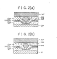
- FIGs. 2(a) and 2(b) are schematic cross-sectional views respectively illustrating an example of an electrode structure (comprising an adhesive body disposed on a surface of a photovoltaic element and a metallic wire as a first collecting electrode embedded in said adhesive body while electrically connected with a bus bar as a second collecting electrode) for a photovoltaic device according to the present invention, where a cross section of an end portion of said electrode structure in each case is shown.
- an electrode structure comprising an adhesive body disposed on a surface of a photovoltaic element and a metallic wire as a first collecting electrode embedded in said adhesive body while electrically connected with a bus bar as a second collecting electrode
- reference numeral 201 indicates a photovoltaic element (comprising at least a photoelectric conversion semiconductor layer, and a transparent and electrically conductive layer, formed on an electrically conductive surface of a substrate as well as in the case shown in FIGs. 1(a) through 1(c)), reference numeral 202 a adhesive body comprising a polymer film 203 interposed between two adhesive materials 204, reference numeral 205 an end portion of a metallic wire as a first collecting electrode (this will be hereinafter simply as metallic wire), reference numeral 206 an electrically conductive adhesive, and reference numeral 207 a bus bar as a second collecting electrode.
- a photovoltaic element comprising at least a photoelectric conversion semiconductor layer, and a transparent and electrically conductive layer, formed on an electrically conductive surface of a substrate as well as in the case shown in FIGs. 1(a) through 1(c)
- reference numeral 202 a adhesive body comprising a polymer film 203 interposed between two adhesive materials 204, reference nume
- the metallic wire 205 coated by the electrically conductive adhesive 206 is arranged such that it is embedded in the adhesive body 202 while being contacted with the bus bar.
- the metallic wire 205 with no coat of the electrically conductive adhesive 206 is arranged such that it is embedded in the adhesive body 202 while being contacted with the bus bar through a layer comprising the electrically conductive adhesive 206.
- the electrically conductive adhesive of the metallic wire 206 is not always necessary to be disposed on the entire of the metallic wire 205.
- the electrically conductive adhesive may be disposed such that at least a part of the metallic wire 205 to be contacted with the bus bar 207 is provided with the adhesive. If necessary, the bus bar may be also provided with an electrically conductive adhesive (this is not shown in the figure).
- the photovoltaic element is provided with a transparent and electrically conductive layer formed on the surface thereof.
- the surface of the photovoltaic element 201 on which the adhesive body 202 is to be disposed may be an exposed surface of the photoelectric conversion layer, an exposed surface of the substrate or an exposed surface of the transparent and electrically conductive layer.
- the surface region of the photovoltaic element 201 on which the above electrode structure configuration shown in FIG. 1(a) or 1(b) is established will be hereinafter occasionally referred to as "metallic wire's end portion-fixing surface region 201".
- FIG. 3(a) is a schematic cross-sectional view illustrating an example of a configuration of a first collecting electrode disposed on a photovoltaic element in the present invention.
- FIG. 3(b) is a schematic cross-sectional view illustrating another example of a configuration of a first collecting electrode disposed on a photovoltaic element in the present invention.
- reference numeral 301 indicates a photovoltaic element
- reference numeral 300 a first collecting electrode comprising a metallic wire 302 and an electrically conductive adhesive 303.
- FIG. 3(a) shows a case wherein the first collecting electrode 300 comprising the metallic wire 302 coated by the electrically conductive adhesive 303 is bonded onto the surface of photovoltaic element 301 through the electrically conductive adhesive 303.
- FIG. 3(b) shows a case wherein the metallic wire 302 is first arranged on the surface of the photovoltaic element 301, and the surface of the metallic wire 302 is partially coated by the electrically conductive adhesive.
- FIG. 4(a) is a schematic plan view illustrating another example of a photovoltaic device according to the present invention.
- FIG. 4(b) is a schematic cross-sectional view, taken along the line A-A' in FIG. 4(a).
- FIG. 4(c) is a schematic cross-sectional view, taken along the line B-B' in FIG. 4(a).
- reference numeral 401 indicates a substrate having an electrically conductive surface
- reference numeral 402 a photovoltaic device (comprising a photoelectric conversion semiconductor layer) formed on the entire electrically conductive surface of the substrate 401
- reference numeral 406 a transparent and electrically conductive layer as an upper electrode formed on the surface of the semiconductor layer of the photovoltaic element 402.
- Reference numeral 403 indicates a metallic wire 403 as a first collecting electrode, reference numeral 404 a bus bar as a second collecting electrode, and reference numeral 405 an adhesive body.
- Reference numeral 407 indicates a region with no transparent and electrically conductive layer, which is formed by removing each of opposite side partial portions of the transparent and electrically conductive layer 406 by way of etching or the like to establish a power-generating layer region 406b of the transparent and electrically conductive layer 406 (which effectively works for power generation) and opposite electrically isolated non-power generating regions 406a of the transparent and electrically conductive layer 406 (each of which serves as a portion for disposing a bus bar 404 thereon).
- This electrode structure is effective in further ensuring electrical insulation between the electrode (the lower electrode) on the substrate side and the bus bar 404.
- An adhesive body 405 is arranged and fixed on each of the opposite non-power generating regions 406a.
- a plurality of metallic wires 403 (which may be provided with an electrically conductive adhesive such a way as described in the case of the photovoltaic device shown in FIGs. 1(a) through 1(c)) are spacedly arranged so as to situate on the power generating region 406b and the opposite non-power generating regions 406a, wherein the opposite end portions of each metallic wire 403 are fixed by means of the adhesive bodies 405.
- a bus bar 404 comprising a metal body is arranged on each of the opposite adhesive bodies 405 so as to sandwich the metallic wires 403 between the bus bars 404 and the adhesive bodies 405, wherein the bus bars 404 are also fixed by means of the adhesive bodies 405.
- the metallic wires 403 are arranged such that their end portions are embedded in the adhesive body 405 while being sandwiched between the adhesive body 405 and the bus bar 404, wherein the bus bar 404 is also contacted with the adhesive body 405.
- FIGs. 4(a) through 4(c) is suitable particularly in the case of using a photovoltaic element formed on a long substrate.
- FIG. 5 is a schematic cross-sectional view illustrating an example of a solar cell module in which a plurality of photovoltaic devices according to the present invention are integrated in series connection.
- the solar cell module shown in FIG. 5 comprises an integrated body comprising a plurality of photovoltaic devices 501 according to the present invention integrated in series connection is sealed together with an electrically insulating film 505 disposed on the rear side of the integrated body on a back face reinforcing member. 502 by means of a sealing resin 503, and an exposed exterior of the resin sealed body is covered by a surface protective layer 504.
- electrically insulating film 505 are nylon film, PET film and the like.
- back face reinforcing member 502 are metal plate, plastic plate, glass plate and the like.
- the sealing resin 503 it is desired to use a resin excelling in weatherability, adhesion, packing property, heat resistance, cold resistance and impact resistance.
- a resin excelling in weatherability, adhesion, packing property, heat resistance, cold resistance and impact resistance.
- EVA ethylene-vinyl acetate copolymer
- EEA ethylene-ethyl acrylate copolymer
- the surface protective layer is constituted by a transparent fluororesin in order for the solar cell module to be of light weight and to have flexibility.
- fluororesin are ETFE (ethylene-tetrafluoroethylene copolymer) such as TEFZEL (trademark name, produced by Du Pont Company), polyvinyl fluoride such as TEDLAR (trademark name, produced by Du Pont Company), and the like.
- the fluororesin by which the surface protective layer is constituted may contain an UV absorber in order to improve the weatherability thereof.
- the resin sealing of the above integrated body may be conducted in a conventional lamination manner using a vacuum laminater, where thermocompression bonding is conducted in a vacuumed atmosphere.
- a light transmissive member such as a glass plate
- the light transmissive member may be used as the surface protective layer.
- the foregoing integrated body of the photovoltaic devices is sealed by the foregoing sealing resin, and the rear side is protected by a film of the foregoing fluororesin or a film of PET (poly(ethyleneterephthalate)).
- a solar cell module having such configuration as shown in FIG. 5 according to the present invention is made into a solar cell-integrated construction member usable as a roofing member or walling member by properly bending one or both opposite end portions of the back face reinforcing member.
- the solar cell-integrated construction member herein may be designed as shown in FIG. 7(a), 7(b) or 7(c).
- FIG. 7(a) is a schematic explanatory view illustrating a roofing member comprising a plane portion 700 having a photovoltaic device according to the present invention disposed therein and which is provided with a fastening portion 701 on a ridge side and another fastening portion 702 on an eaves side.
- FIG. 7(b) is a schematic explanatory view illustrating another roofing member comprising a plane portion 700 having a photovoltaic device according to the present invention disposed therein and which is provided with fastening portions 703 to be engaged with anchors 704 secured on a roof board 705.
- FIG. 7(b) is a schematic explanatory view illustrating another roofing member comprising a plurality of roofing members each having a plane portion 700 containing a photovoltaic device according to the present invention and having two fastening portions 706, where each adjacent roofing members are integrated by securing their fastening portions by means of capping members 707 as shown in FIG. 7(c).
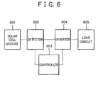
- FIG. 6 is a schematic diagram illustrating a power conversion apparatus as an example in the case of using the solar cell module according to the present invention as a power supply source.
- the power conversion apparatus shown in FIG. 6 comprises the solar cell module 601 according to the present invention, a detector 602 for detecting a voltage and an electric current of the solar cell module, a controller 603, and an inverter 604.
- the controller 603 herein serves to control the inverter 604 depending on an output detected by the detector.
- the power conversion apparatus is also provided with a load circuit 605 connected to the inverter 604.
- the power generated by the solar cell module 601 is supplied into the load circuit 605 through the above mechanism of the power conversion apparatus.
- the power conversion apparatus may be provided with a linkage function to a commercial electric power system.
- the adhesive body 202 which is disposed on the metallic wire-fixing region 201 and which serves to fix the metallic wire 205 and the bus bar 207, there is used a stacked body comprising a heat resistant polymer film 203 having opposite surfaces each having an adhesive material 204 stacked thereon.
- the stacked body can include so-called double-coated tapes and other laminate products comprising a plurality of polymer films and a plurality of adhesive layers which are alternately stacked such that each of the top and bottom layers comprises an adhesive layer.
- the laminate product it is possible to use a plurality of different kind heat resistant polymer films or a plurality of different kind adhesive layers.
- double-coated tape or laminate product usable as the adhesive body 202 there can be mentioned a commercially available double-coated tape DOUBLE FACE LEW411A (having a width of 7 mm) (trademark name, produced by Toyo Ink Kabushiki Kaisha), comprising a 0.050 mm thick adhesive layer of polydimethylsiloxane/a 0.025 mm thick polymer film of polyimide/a 0.025 mm thick adhesive layer of polydimethylsiloxane/a 0.075 mm thick polymer film of polyester/a 0.050 mm thick adhesive layer of polydimethylsiloxane.
- DOUBLE FACE LEW411A having a width of 7 mm
- the polymer film 203 is used together with the adhesive 204 as a part of the adhesive body 202 in order to dispose the metallic wire 205 or the bus bar 207 on the photovoltaic element.
- the polymer film 203 is desired to be heat resistant for the purpose of protecting the photovoltaic element from being damaged by heat of a solder, or bur or fracture of the bus bar oupon connecting the metallic wire 205 or a by-pass diode to the bus bar 207.
- the polymer film 203 is desired to have an electrically insulating property in order to prevent the metallic wire 205 from being short-circuited with the lower electrode on the substrate side.
- the polymer material by which the polymer film 203 is constituted can include cellophane, rayon, acetate, polyethylene, polyethylene terephthalate, polyether ketone, fluororesin, polysulfone, unsaturated polyester, epoxy resin, polyamide resin, polyimide resin, polyamide-imide resin, and polyimide-silicone resin.
- polyimide resin and polyethylene terephthalate are the most appropriate in terms of adhesion with the adhesive 204, low thermal expansion, and physical strength.
- the polymer film 203 is desired to have a melting point of 250 °C or above.
- Adhesive Material 204 Adhesive Material 204
- the adhesive material 204 may comprise one or more adhesive materials selected from the group consisting of acrylic adhesive materials, rubber series adhesive materials, silicone series adhesive materials, polyvinyl ether series adhesive materials, expoxy series adhesive materials, polyurethane series adhesive materials, nylon series adhesive materials, polyamide series adhesive materials, inorganic adhesive materials, and composite type adhesive materials. Of these, those satisfactory in adhesion, tuck, holding power, antistatic property, heat resistance and moisture resistance are desirably used. Acrylic adhesive materials and silicone series adhesives are particularly more appropriate since they excel in durability, holding power, and heat resistance. Of these, silicone series adhesive materials are the most appropriate since they are desirably low in moisture absorption and excels in moisture resistance.
- an adhesive material layer as the adhesive material 204 may be conducted in a manner of forming a coat layer having a uniform width using an applicator or the like, wherein after-treatment such as drying treatment, heat treatment, compression treatment, or light irradiation treatment may be conducted for the resulting coat layer depending upon the kind of an adhesive material used.
- the adhesive material 204 is desired to be designed such that it has a hygroscopicity preferably in the range of 0.0 % to 1.5 %, more preferably in the range of 0.01 % to 1.0 % or less when maintained in an atmosphere of 40 °C/80 %RH for 12 hours. In this case, it is possible to desirably attain the formation of a resin seal having a defect-free good exterior appearance for a photovoltaic device in the resin sealing process.
- the metallic wire 205 used as a first collecting electrode for a photovoltaic device is desired to be constituted by a metal or alloy having a low electric resistance.
- a metal or alloy having a low electric resistance can include, for example, Cu, Ag, Au, Pt, Al, Mo, and W and such alloy can include, for example, alloys of these metals.
- the metallic wire 205 prefferably has a thin surface protective metal layer formed on the surface thereof for the purposes of preventing it from corroding or oxidizing, improving its adhesion with an electrically conductive resin, and improving its electrical conductivity.
- the surface protective metal layer is desired to be constituted by a metallic material which is difficult to be corroded or excels in corrosion resistance.
- metallic material are Ag, Pd, Ag-Pd alloy, Au, Ni, and Sn.
- the surface protective metal layer may be formed by way of plating or cladding.
- the surface protective metal layer may be a coat layer formed by using an electrically conductive resin composition comprising particles of the foregoing metallic material dispersed in a binder resin.
- the thickness of the coat layer should be properly determined depending upon the situation involved. For instance, when the metallic wire 205 has a circular cross section, it is desired for the coat layer to have a thickness corresponding to 1 to 10 % of the diameter of the circular cross section of the metallic wire.
- the metallic wire 205 is desired to of a circular cross section. But it may be of a cross section in other form such as rectangular form depending upon the situation involved.
- the diameter of the metallic wire 205 it should be properly designed so that the sum of a loss of electric resistance and a shadow loss is minimized. Specifically, it is preferably in the range of 25 ⁇ m to 1 mm, more preferably in the range of 25 ⁇ m to 200 ⁇ m. In the case where the diameter is less than 25 ⁇ m, the metallic wire is liable to entail problems such that it is sometimes broken and a relatively large electricity loss is caused.
- the shadow loss which means an area occupied by the metallic wire over the surface of the photovoltaic element
- irregularities which are undesirably large in size are established on the surface of the photovoltaic element and because of this, it is necessary to thicken the thickness of a resin seal by means of a sealing resin such as EVA to be formed in the resin sealing by means of vacuum lamination or the like.
- Such a metallic wire as the metallic wire 205 may be prepared by means of a conventional wire drawing machine capable of producing a metallic wire having a desired diameter.
- the metallic wire produced by the wire drawing machine is hard. Therefore, in order to make the hard metallic wire have a reasonable extensibility and bendability, it may be softened by subjecting to annealing treatment.
- the electrically conductive adhesive 206 which is disposed on the surface of the metallic wire 205 while contacting with the bus bar 207 functions to efficiently collect a photovoltaic force, whereby making the photovoltaic device exhibit desirable photovoltaic characteristics.
- a given electrically conductive adhesive composition is applied on the entire surface or a desired partial surface area of the metallic wire 205 by means of a conventional coating process, followed by subjecting to thermocompression treatment.
- the electrically conductive adhesive 206 may be disposed on the side of the bus bar 207 so that the metallic wire 206 is electrically connected to the bus bar 207 through the electrically conductive adhesive.
- a adhesive coat layer is formed on a surface of the bus bar 207 to be contacted with the metallic wire 205 by applying a given electrically conductive adhesive composition on said surface of the bus bar 207, the bus bar having said adhesive coat is superpose on the metallic wire, followed by subjecting to' thermocompression treatment.
- the electrically conductive adhesive 206 for bonding the metallic wire 205 to the bus bar 207 comprises an electrically conductive composition comprising electrically conductive particles of an electrically conductive material dispersed in a binder resin.
- a binder resin it is desired to use a polymer resin which enables to readily form a coating film on the surface of the metallic wire, excels in heat resistance and workability, and has flexibility.
- Such polymer resin can include heat-curable resins and thermoplastic resins.
- the heat-curable resin are epoxy resins, urethane resins, phenol resins, polyvinyl formals, alkyd resins, and modified resins of these resins.
- urethane resins are particularly desirable because they often have being used as an insulating coating material for an enameled wire and excel in flexibility and also in productivity.
- thermoplastic resin examples include polyamide resins, melamine resins, butyrals, phenoxy resins, polyimide resins, fluororesins, acrylic resins, styrene resins, and polyester resins.
- the electrically conductive material for the electrically conductive particles dispersed in the binder resin can include pigments capable of imparting electrically conductivity.
- pigments capable of imparting electrically conductivity.
- Specific example of such pigment are graphite, carbon black, metal oxides such as In 2 O 3 , TiO 2 , SmO 2 , ITO and ZnO, oxide semiconductors comprising these metal oxides added with a dopant.
- the electrically conductive particles it is necessary for the electrically conductive particles to have a mean particle size which is smaller than the thickness of an electrically conductive adhesive layer as the electrically conductive adhesive 206.
- the electrically conductive particles are desired to have a mean particle size in the range of 0.02 um to 15 ⁇ m.
- the electrically conductive particles are mixed with the foregoing polymer resin at an appropriate mixing ratio so that a desired resistivity can be obtained.
- a drawback entails in that since the content of the polymer resin is undesirably small, it is difficult to form a coating film having desired stability.
- the electrically conductive particles are difficult to be contacted with each other as desired, resulting in an excessive increase in the resistance.
- the mixing ratio between the electrically conductive particles and the polymer resin it should be adequately determined depending upon the kind of electrically conductive particles used and that of a polymer resin used and also depending upon the physical properties of these. Specifically, there can be attained a desirable resistivity by making the electrically conductive particles to be in the range of 5 volume% to 95 volume%.
- the electrically conductive adhesive 206 is necessary to be designed to have such a thickness that its resistivity can be disregarded in collecting an electric current generated by the photovoltaic element and a shunt, which will be a cause of entailing migration of a metal ion from the metallic wire 205, is not occurred.
- the electrically conductive adhesive 206 is designed to have a thickness exhibiting a shunt resistance of 0.01 ⁇ .cm to 100 ⁇ .cm for the following reasons. That is, when the shunt resistance of the electrically conductive adhesive 206 is less than 0.01 ⁇ .cm, it is inferior in barrier function for preventing occurrence of a shunt. And when the shunt resistance of the electrically conductive adhesive is beyond 100 .cm, the loss in electric resistance is increased.
- the preparation of a desirable electrically conductive composition comprising the foregoing electrically conductive particles dispersed in the foregoing polymer resin for the formation of the electrically adhesive 206 may be conducted using a conventional dispersing apparatus such as triple roll mill, paint shaker, or beads mill.
- a conventional dispersing apparatus such as triple roll mill, paint shaker, or beads mill.
- an appropriate dispersant In order to facilitate the dispersion of the electrically conductive particles in the polymer resin, it is possible to use an appropriate dispersant. Further, during or after the dispersing operation, it is possible to add an appropriate solvent in order to adjust the viscosity of the polymer resin.
- the bus bar 207 is disposed over the metallic wire's end portion-fixing surface region 201.
- the metallic wire's fixing surface region 201 (which means one of opposite edge portions of the surface of the photovoltaic element where an end portion of the metallic wire 205 is fixed) includes the following embodiments.
- the bus bar 207 is constituted by a metallic material having a low electric resistance such as a metal or metal alloy.
- Such metallic material are metals such as Cu, Ag, Au, Pt, Al, Sn, Pb and Ni, and alloys of these metals.
- the bus bar 207 prefferably has a thin surface protective metal layer formed on the surface thereof to be electrically connected with the metallic wire 206 for the purposes of preventing it from corroding or oxidizing, improving its adhesion with an electrically conductive resin, and improving its electrical conductivity as well as in the case of the metallic wire 205.
- the surface protective metal layer may be formed by way of plating or cladding as well as in the case of the metallic wire 205.
- an electrically conductive paste is applied on at least a part of the surface of the bus bar 207 to be electrically connected with the metallic wire 205 such that the bus bar is electrically connected to the metallic wire through the electrically conductive paste.
- the bus bar 207 may be shaped in a web-like foil form' or a wire form.
- the photovoltaic element 102 used in the present invention is desired to comprise a substrate 101, a first electrode (or a lower electrode) disposed on said substrate, a photoelectric conversion semiconductor layer (which contributes to power generation) disposed on said first electrode, and a second electrode (comprising a metallic wire) disposed on a light receiving surface of said photoelectric conversion semiconductor layer.
- a transparent and electrically conductive layer is disposed between the photoelectric conversion semiconductor layer and the second electrode for light reflection preventive purpose.
- the first electrode is disposed on the rear side of the photoelectric conversion semiconductor layer as above described.
- the first electrode may comprise a metallic layer formed, for instance, by way of screen printing or vacuum deposition.
- the metallic layer in this case may be constituted by an adequate metallic material capable of providing a good ohmic contact with the photoelectric conversion semiconductor layer.
- the photoelectric conversion semiconductor layer when it comprises an amorphous material film such as an amorphous silicon film (an a-Si film), it is necessary to have a substrate for retaining said amorphous material film.
- a substrate for retaining said amorphous material film.
- an electrically conductive member or an electrically insulating member having an electrically conductive surface may be used.
- the first electrode is formed on the substrate.
- the first electrode may comprise a metallic member constituted by, for instance, stainless steel or aluminum.
- the first electrode may comprise an electrically insulating member (constituted by, for instance, glass, polymer resin, or ceramics) having an electrically conductive surface composed of an electrically conductive material such as Cu, Al, or Ag formed, for instance, by way of vacuum deposition.
- the first electrode may be formed by way of screen printing using an Ag-paste, without using the substrate.
- an end portion of the fist electrode on the substrate which corresponds a non-power generation region where the bus bar 104 is arranged, may be removed in order to ensure electrical insulation between the upper and lower electrodes.
- the photoelectric conversion layer is necessary to have a structure with a semiconductor junction such as pn junction, pin junction, Schottky junction or the like.
- the photoelectric conversion semiconductor layer having such semiconductor junction is constituted by an adequate semiconductor material.
- semiconductor material there can be illustrated semiconductor materials comprising an element belonging to group IV of the periodic table such as single crystalline silicon semiconductor material, polycrystalline silicon (poly-Si) semiconductor material, amorphous silicon (a-Si) semiconductor material, and microcrystalline silicon ( ⁇ c-Si) semiconductor material; semiconductor conductor materials comprising elements belonging to groups II and VI of the periodic table such as CdS semiconductor material and CdTe semiconductor material; and semiconductor materials comprising elements belonging to groups III and V of the periodic table such as GaAs semiconductor material and the like.
- the photoelectric conversion layer may comprise a single cell structure comprising a single cell with a pn or pin junction, a tandem cell structure comprising two cells having a pn or pin junction being stacked, or a triple cell structure comprising three cells having a pn or pin junction being stacked.
- the tandem cell structure can include, for example, a stacked cell structure comprising a bottom cell with a pin junction and a top cell with a pin junction being stacked wherein each of the two cells comprises an n-type semiconductor layer, an i-type semiconductor layer (comprising an a-Si semiconductor layer) and a p-type semiconductor layer being stacked; and a stacked cell structure comprising a bottom cell with a pin junction and a top cell with a pin junction being stacked wherein the bottom cell comprises an n-type semiconductor layer, an i-type semiconductor layer (comprising an a-SiGe semiconductor layer) a p-type semiconductor layer being stacked, and the top cell comprises an n-type semiconductor layer, an i-type semiconductor layer (comprising an a-Si semiconductor layer) and a p-type semiconductor layer being stacked.
- the bottom cell it is possible for the bottom cell to be of a two-layered structure with a pn junction comprising
- the triple cell structure can include, for example, a stacked cell structure comprising a bottom cell with a pin junction, a middle cell with a pin junction and a top cell with a pin junction being stacked wherein each of the three cells comprises an n-type semiconductor layer, an i-type semiconductor layer and a p-type semiconductor layer being stacked, the i-type semiconductor layer in each of the middle and top cells comprises an a-Si semiconductor layer, and the i-type layer in the bottom cell comprises an a-SiGe semiconductor layer; and a stacked cell structure comprising a bottom cell with a pin junction, a middle cell with a pin junction and a top cell with a pin junction being stacked wherein each of the three cells comprises an n-type semiconductor layer, an i-type semiconductor layer and a p-type semiconductor layer being stacked, the i-type semiconductor layer in the top cell comprises an a-Si semiconductor layer, and the i-type layer in each of the middle and bottom cell comprises an a--
- the semiconductor layer of p- or n-type situated on the light incident side may be constituted by a microcrystalline ( ⁇ c-) semiconductor material.
- the photoelectric conversion layer of the photovoltaic element is not limited to these embodiments.
- the transparent and electrically conductive layer is constituted by an appropriated transparent and electrically conductive material.
- transparent and electrically conductive material are ITO, SnO 2 , In 2 O 3 , and the like.
- the second electrode comprising the metallic wire is disposed on the light incident face side of the photoelectric conversion semiconductor layer as previously described.
- the metallic wire as the first collecting electrode a plurality of metallic wires are used, and it is desired for them to be spacedly arranged at a desired interval and in parallel to each other so that the sum of the electric resistance by the metallic wires and the shadow loss due to the metallic wires is minimized.
- the sheet resistance of the transparent and electrically conductive layer is about 100 ⁇ / ⁇
- t he metallic wires are desired to be spacedly arranged at an interval of about 5 mm.
- a photovoltaic device according to the present invention may be produced, for example, in the following manner.
- a photovoltaic element comprising a photoelectric conversion semiconductor layer formed on an electrically conductive surface of a substrate and a transparent and electrically conductive layer formed on the photoelectric conversion semiconductor layer is provided. Part of the transparent and electrically conductive layer situated in the periphery of the photovoltaic element is removed using an adequate etching paste, whereby (a) a power generation region comprising the transparent and electrically conductive layer and (b) opposite non-power generation peripheral regions each comprising an exposed portion of the photoelectric conversion semiconductor layer which is situated outside said power generation region (a) are established on the photovoltaic element. On each of the opposite non-power generation regions (b), any of the foregoing adhesive body is arranged and bonded.
- a plurality of metallic wires coated by an electrically conductive adhesive are spacedly arranged at a desired interval on the photovoltaic element and their end portions are bonded on the opposite adhesive bodies.
- a bus bar (comprising, for example, a hard copper member coated by an Ag-clad) is arranged and bonded on each of the opposite adhesive bodies while electrically connecting to the metallic wires.
- the resultant is subjected to thermocompression treatment, for instance, under conditions of 200 °C for the temperature, 1 Kg/cm 2 for the pressure, and one minute for the treatment period of time.
- thermocompression treatment for instance, under conditions of 200 °C for the temperature, 5 Kg/cm 2 for the pressure, and 15 second for the treatment period of time.
- the solar cell module was prepared in the following manner.
- a coated metallic wire having the cross section shown FIG. 2(a) comprising a metallic wire 205 as a core and an electrically conductive adhesive 206 as a coat layer (or a clad) was prepared in the following manner.
- the resultant wire product was cut to obtain a plurality of collecting electrodes as the metallic wire 403.
- photovoltaic element 402 there was provided a pin junction triple cell type photovoltaic element prepared in the following manner.
- a cleaned plate made of SUS430BA stainless steel of 125 um in thickness as the substrate 401.
- a two-layered lower electrode layer comprising a 5000 ⁇ thick Ag film and a 5000 ⁇ thick ZnO film by means of a conventional sputtering process.
- a photoelectric conversion semiconductor layer having a bottom cell comprising a 400 ⁇ thick n-type a-Si film/a 1000 ⁇ thick i-type a-SiGe film/a 100 ⁇ thick p-type ⁇ c-Si film, a middle cell comprising a 400 ⁇ thick n-type a-Si film/a 900 ⁇ thick i-type a-SiGe film/a 100 ⁇ thick p-type ⁇ c-Si film, and a top cell comprising a 100 ⁇ thick n-type a-Si film/a 1000 ⁇ thick i-type a-Si film/a 100 ⁇ thick p-type ⁇ c-Si film being stacked in the named order from the substrate side by means of a conventional plasma CVD process, where the n-type a-Si film in each of the three cells was formed from a mixture of SiH 4 gas, PH 3 gas and H 2 gas;
- the photovoltaic element was found to a square area 30 cm x 30 cm in size with respect to the photoelectric conversion semiconductor layer.
- FIG. 2(a) The cross section of the configuration in which the collecting electrode is bonded to the bus bar herein is as shown in FIG. 2(a).
- a glass fiber member and a film of EVA ethylene-vinyl acetate copolymer
- EVA ethylene-vinyl acetate copolymer
- ETFE ethylene-tetrafluoroethylene copolymer
- the stacked body was subjected to thermocompression bonding treatment at 160°C for 60 minutes, whereby a solar cell module was obtained.
- the photovoltaic device reserved in the above step 3 was subjected to solder resistance test in the following manner. An iron maintained at 280 °C was pressed onto the bus bar for one minute, followed by pressing another iron maintained at 320 °C onto the bus bar. Thereafter, the bus bar was peeled off from the adhesive body, and the surface state of the polymer layer of the residual adhesive body was optically observed. The observed result is shown in Table 1 based on the following criteria.
- the solar cell module was placed in a solar simulator SPI-SUN SIMULATOR 240A (AM 1.5) (trademark name, produced by SPIRE Company), where a pseudo sunlight spectrum of 100 mW/cm 2 was irradiated to the solar cell module and its V-I characteristics were measured to obtain a V-I characteristic curve. Based on the V-I characteristic curve, an initial photoelectric conversion efficiency was obtained. In this way, there were obtained ten initial photoelectric conversion efficiencies for the ten solar cell modules, and an mean value among the ten photoelectric conversion efficiencies was obtained.
- SPI-SUN SIMULATOR 240A AM 1.5
- the mean photoelectric conversion efficiency value obtained in this example is set at 1.0 in terms of a relative vale for comparison purpose.
- thermo-hygrostat capable of controlling the temperature and humidity of a specimen, where the solar cell module was subjected to alternate repetition of a cycle of exposing to an atmosphere of -40 °C for an hour and a cycle of exposing to an atmosphere of 85 °C/85 %RH for 22 hours 20 times.
- a photoelectric conversion efficiency after the endurance there was obtained.
- Table 1 Example Comparative Example 1 2 3 4 5 1 2 3 photovoltaic device solder resistance ⁇ ⁇ ⁇ ⁇ ⁇ ⁇ ⁇ ⁇ solar cell module exterior appearance after the lamination (1) ⁇ ⁇ ⁇ ⁇ ⁇ ⁇ ⁇ ⁇ (2) ⁇ ⁇ ⁇ ⁇ ⁇ ⁇ ⁇ ⁇ shunt resistance ⁇ ⁇ ⁇ ⁇ ⁇ ⁇ ⁇ ⁇ initial photoelectric conversion efficiency ⁇ ⁇ ⁇ ⁇ ⁇ X ⁇ ⁇ photoelectric Conversion efficiency after endurance ⁇ ⁇ ⁇ ⁇ ⁇ ⁇ ⁇ ⁇ ⁇ (1) : maintained in an atmosphere of 25°C/50%RH (2): maintained in an atmosphere of 35°C/90%RH
- any of the resultant photovoltaic elements excels characteristics required for a photovoltaic element.
- the photovoltaic element according to the present invention excels in solder resistance, namely, it is substantially free of damage due to heat of the solder.
- a desired interval can be maintained between the bus bar and the photovoltaic element and because of this, the photovoltaic element is desirably protected from being suffered from problems due to bur or fracture of the metal body used as the bus bar.
- the photovoltaic element is inferior in solder resistance. Because of this, there is a tendency for the photovoltaic element to be readily short-circuited, whereby the photovoltaic element is inferior not only in initial photoelectric conversion efficiency but also in photoelectric conversion efficiency after the endurance.
- any of the photovoltaic elements obtained in these comparative examples is inferior in solder resistance. Because of this, there is a tendency for any of the photovoltaic elements to be readlly short-circuited, whereby the photovoltaic element is inferior not only in initial photoelectric conversion efficiency but also in photoelectric conversion efficiency after the endurance.
Landscapes
- Photovoltaic Devices (AREA)
Claims (21)
- Fotovoltaikvorrichtung mit
einem Fotovoltaikelement, das ein Substrat mit einer elektrisch leitenden Oberfläche, eine auf der elektrisch leitenden Oberfläche des Substrats ausgebildete Halbleiterschicht, und eine auf der Halbleiterschicht ausgebildete transparente und elektrisch leitende Elektrodenschicht umfasst;
einem Energieerzeugungsbereich mit einer über der transparenten und elektrisch leitenden Elektrodenschicht des Fotovoltaikelements (102, 201, 301, 402) angeordneten metallischen Leiterbahn (103, 205, 302, 403); und
einem Fixierbereich zum Fixieren eines Endabschnitts der metallischen Leiterbahn (103, 205, 302, 403),
dadurch gekennzeichnet, dass
der Endabschnitt der metallischen Leiterbahn (102, 205, 302, 403) mit einer Busleiste (104, 207, 404) in dem Fixierbereich durch einen haftenden Körper (105, 202, 405) in dem Fixierbereich fixiert ist, wobei in dem haftenden Körper eine Polymerschicht zwischen zwei haftenden Materialschichten (204) sandwichartig angeordnet ist, und wobei der Endabschnitt der metallischen Leiterbahn (103, 205, 302, 403) zwischen der Busleiste (104, 207, 404) und dem haftenden Körper (105, 202, 405) in dem Fixierbereich angeordnet ist, während ein elektrischer Kontakt zu der Busleiste (104, 207, 404) derart ausgebildet ist, dass der Endabschnitt der metallischen Leiterbahn durch den haftenden Körper eingebettet ist, und die Busleiste ebenfalls mit dem fotovoltaischen Element durch den haftenden Körper fixiert ist. - Fotovoltaikvorrichtung nach Anspruch 1, wobei der Fixierbereich einen Teil eines freigelegten Abschnitts des Substrats umfasst.
- Fotovoltaikvorrichtung nach Anspruch 1, wobei der Fixierbereich einen Teil eines freigelegten Abschnitts der Halbleiterschicht umfasst.
- Fotovoltaikvorrichtung nach Anspruch 1, wobei der Fixierbereich auf einem Teil der transparenten und elektrisch leitenden Elektrodenschicht angeordnet ist, und der Teil der transparenten und elektrisch leitenden Elektrodenschicht einen Nichtverbindungsteil der transparenten und elektrisch leitenden Elektrodenschicht mit der Halbleiterschicht aufweist.
- Fotovoltaikvorrichtung nach Anspruch 1, wobei der Fixierbereich durch Entfernen von zumindest einem Teil der transparenten und elektrisch leitenden Elektrodenschicht ausgebildet ist.
- Fotovoltaikvorrichtung nach Anspruch 1, wobei zumindest ein Teil der metallischen Leiterbahn (103, 205, 302, 403) mit der Oberfläche der transparenten und elektrisch leitenden Elektrodenschicht auf der Halbleiterschicht mittels eines elektrisch leitenden Haftmittels (206, 303) fixiert ist.
- Fotovoltaikvorrichtung nach Anspruch 1, wobei die haftende Materialschicht (204) eine Hygroskopizität von 0,0 % bis 1,5 % aufweist, wenn es in einer Atmosphäre von 40°C/80 % RH für 12 Stunden gehalten wird.
- Fotovoltaikvorrichtung nach Anspruch 1, wobei das haftende Material (204) ein oder mehr haftende Haftmaterialien aus der Gruppe acrylische haftende Materialien, haftende Materialien der Gummireihe, haftende Materialien der Silikonreihe, haftende Materialien der Polyvinylätherserie, haftende Materialien der Epoxydreihe, haftende Materialien der Polyurethanreihe, haftende Materialien der Nylonreihe, haftende Materialien der Polyamidreihe, anorganische haftende Materialien, und zusammengesetzte haftende Materialien aufweist.
- Fotovoltaikvorrichtung nach Anspruch 1, wobei die Polymerschicht eine Polymerharzschicht aufweist, die zumindest einen Schmelzpunkt von mehr als 250°C aufweist.
- Fotovoltaikvorrichtung nach Anspruch 1, wobei die Polymerschicht aus einem oder mehr Materialien aus der Gruppe Zellophan, Viskose, Acetat, Polyäthylen, Polyäthylenterephthalat, Polyätherketon, Fluorharz, Polysulfon, ungesättigte Polyester, Epoxydharz, Polyamidharz, Polyamidimidharz und Polyimidsilikonharz aufweist.
- Fotovoltaikvorrichtung nach Anspruch 1, wobei die Halbleiterschicht ein nicht einkristallines Halbleitermaterial umfasst.
- Fotovoltaikvorrichtung nach Anspruch 1, wobei die metallische Leiterbahn (103, 205, 302, 403) mit der Busleiste (104, 207, 404) mittels eines elektrisch leitenden Haftmittels (206, 303) elektrisch verbunden ist.
- Fotovoltaikvorrichtung nach Anspruch 1, wobei zumindest ein Teil der Busleiste (104, 207, 404) ein darauf aufgebrachtes elektrisch leitendes Haftmittel (206, 303) aufweist.
- Fotovoltaikvorrichtung nach Anspruch 1, wobei zumindest ein Teil der metallischen Leiterbahn (103, 205, 302, 403) mit der Oberfläche der transparenten und elektrisch leitenden Elektrodenschicht auf der Halbleiterschicht mittels des elektrisch leitenden Haftmittels (206, 303) fixiert ist.
- Verfahren zur Herstellung einer Fotovoltaikvorrichtung nach Anspruch 1, gekennzeichnet durch die Schritte:Anordnen des haftenden Körpers (105, 202, 405) mit zwei haftenden Materialschichten (204) und einer zwischen den beiden haftenden Materialschichten (204) in dem Fixierbereich sandwichartig angeordneten Polymerschicht,Anordnen der metallischen Leiterbahn (103, 205, 302, 403) sowohl auf dem haftenden Körper (105, 202, 405) als auch auf der transparenten und elektrisch leitenden Elektrodenschicht auf der Halbleiterschicht,Anordnen der Busleiste (104, 207, 404) sowohl auf dem haftenden Körper (105, 202, 405) als auch auf der metallischen Leiterbahn (103, 205, 302, 403), undVerbinden der metallischen Leiterbahn (103, 205, 302, 403) mit der Busleiste (104, 207, 404) in dem Fixierbereich mittels des haftenden Körpers (105, 202, 405) und durch Wärme und/oder Druck.
- Verfahren nach Anspruch 15, das ferner einen Schritt zur vorherigen Beschichtung der metallischen Leiterbahn (103, 204, 302, 403) mit einem elektrisch leitenden Haftmittel (206, 303) aufweist.
- Verfahren nach Anspruch 15, das ferner einen Schritt zum Verbinden der metallischen Leiterbahn (103, 205, 302, 403) auf der Oberfläche der transparenten und elektrisch leitenden Elektrodenschicht auf der Halbleiterschicht aufweist.
- Verfahren nach Anspruch 17, wobei der Schritt zum Verbinden der metallischen Leiterbahn (103, 205, 302, 403) auf der Oberfläche der transparenten und elektrisch leitenden Elektrodenschicht auf der Halbleiterschicht gleichzeitig mit dem Schritt zum Verbinden der metallischen Leiterbahn (103, 205, 302, 403) mit der Busleiste (104, 207, 404) ausgeführt wird.
- Solarzellenmodul mit einer Fotovoltaikvorrichtung nach Anspruch 1, die auf einem verstärkenden Material mit Harz versiegelt ist, und einer Schutzschicht, durch die die Fotovoltaikvorrichtung bedeckt ist.
- Konstruktionselement mit einer Fotovoltaikvorrichtung nach Anspruch 1, die auf einem verstärkenden Material mit Harz versiegelt ist, und einer Schutzschicht, durch die die Fotovoltaikvorrichtung bedeckt ist, wobei ein Teil des verstärkenden Materials gebogen ist.
- Energiewandlergerät mit einem Solarzellenmodul nach Anspruch 19, und einer Steuereinrichtung zum Steuern von aus dem Solarzellenmodul ausgegebener Energie.
Applications Claiming Priority (2)
| Application Number | Priority Date | Filing Date | Title |
|---|---|---|---|
| JP146543/96 | 1996-05-17 | ||
| JP14654396 | 1996-05-17 |
Publications (3)
| Publication Number | Publication Date |
|---|---|
| EP0807980A2 EP0807980A2 (de) | 1997-11-19 |
| EP0807980A3 EP0807980A3 (de) | 1998-12-23 |
| EP0807980B1 true EP0807980B1 (de) | 2006-06-21 |
Family
ID=15410039
Family Applications (1)
| Application Number | Title | Priority Date | Filing Date |
|---|---|---|---|
| EP97108076A Expired - Lifetime EP0807980B1 (de) | 1996-05-17 | 1997-05-16 | Photovoltaische Anordnung und Herstellungsverfahren |
Country Status (8)
| Country | Link |
|---|---|
| US (1) | US6121542A (de) |
| EP (1) | EP0807980B1 (de) |
| KR (1) | KR100288866B1 (de) |
| CN (1) | CN1103124C (de) |
| AU (1) | AU693738B2 (de) |
| DE (1) | DE69736151T2 (de) |
| ID (1) | ID16930A (de) |
| ZA (1) | ZA974261B (de) |
Cited By (1)
| Publication number | Priority date | Publication date | Assignee | Title |
|---|---|---|---|---|
| WO2016043353A1 (ko) * | 2014-09-15 | 2016-03-24 | 주식회사 테스 | 태양전지모듈 |
Families Citing this family (118)
| Publication number | Priority date | Publication date | Assignee | Title |
|---|---|---|---|---|
| WO2000002243A1 (en) * | 1998-07-01 | 2000-01-13 | Seiko Epson Corporation | Semiconductor device, method of manufacture, circuit board, and electronic device |
| SE518454C2 (sv) * | 1999-01-15 | 2002-10-08 | Forskarpatent I Uppsala Ab | Metod för framställning av en elektrokemisk cell samt elektrokemisk cell |
| US8076568B2 (en) | 2006-04-13 | 2011-12-13 | Daniel Luch | Collector grid and interconnect structures for photovoltaic arrays and modules |
| US20090111206A1 (en) | 1999-03-30 | 2009-04-30 | Daniel Luch | Collector grid, electrode structures and interrconnect structures for photovoltaic arrays and methods of manufacture |
| US8222513B2 (en) | 2006-04-13 | 2012-07-17 | Daniel Luch | Collector grid, electrode structures and interconnect structures for photovoltaic arrays and methods of manufacture |
| US8664030B2 (en) | 1999-03-30 | 2014-03-04 | Daniel Luch | Collector grid and interconnect structures for photovoltaic arrays and modules |
| US8138413B2 (en) | 2006-04-13 | 2012-03-20 | Daniel Luch | Collector grid and interconnect structures for photovoltaic arrays and modules |
| US7507903B2 (en) * | 1999-03-30 | 2009-03-24 | Daniel Luch | Substrate and collector grid structures for integrated series connected photovoltaic arrays and process of manufacture of such arrays |
| JP2001111076A (ja) * | 1999-10-08 | 2001-04-20 | Tdk Corp | コーティング体および太陽電池モジュール |
| US7898053B2 (en) | 2000-02-04 | 2011-03-01 | Daniel Luch | Substrate structures for integrated series connected photovoltaic arrays and process of manufacture of such arrays |
| US8198696B2 (en) | 2000-02-04 | 2012-06-12 | Daniel Luch | Substrate structures for integrated series connected photovoltaic arrays and process of manufacture of such arrays |
| US7898054B2 (en) | 2000-02-04 | 2011-03-01 | Daniel Luch | Substrate structures for integrated series connected photovoltaic arrays and process of manufacture of such arrays |
| EP1290736A2 (de) * | 2000-06-15 | 2003-03-12 | Akzo Nobel N.V. | Solarzellenanordnung mit einer abnehmbaren oberflächenschicht |
| JP2002112459A (ja) * | 2000-09-29 | 2002-04-12 | Canon Inc | 太陽電池モジュールおよび発電装置 |
| JP2003037281A (ja) | 2001-05-17 | 2003-02-07 | Canon Inc | 被覆材及び光起電力素子 |
| US7211828B2 (en) | 2001-06-20 | 2007-05-01 | Semiconductor Energy Laboratory Co., Ltd. | Light emitting device and electronic apparatus |
| TW548860B (en) | 2001-06-20 | 2003-08-21 | Semiconductor Energy Lab | Light emitting device and method of manufacturing the same |
| US7230271B2 (en) * | 2002-06-11 | 2007-06-12 | Semiconductor Energy Laboratory Co., Ltd. | Light emitting device comprising film having hygroscopic property and transparency and manufacturing method thereof |
| DE10239845C1 (de) * | 2002-08-29 | 2003-12-24 | Day4 Energy Inc | Elektrode für fotovoltaische Zellen, fotovoltaische Zelle und fotovoltaischer Modul |
| JP2004228333A (ja) * | 2003-01-23 | 2004-08-12 | Canon Inc | 光起電力セル、及びその製造方法 |
| US20040181517A1 (en) * | 2003-03-13 | 2004-09-16 | Younghee Jung | System and method for social interaction |
| JP2005123445A (ja) * | 2003-10-17 | 2005-05-12 | Canon Inc | 光起電力素子および光起電力素子の製造方法 |
| ES2365904T3 (es) * | 2004-01-13 | 2011-10-13 | Sanyo Electric Co., Ltd. | Dispositivo fotovoltaico. |
| US20070074755A1 (en) * | 2005-10-03 | 2007-04-05 | Nanosolar, Inc. | Photovoltaic module with rigidizing backplane |
| US8759663B2 (en) * | 2004-03-31 | 2014-06-24 | Sanyo Electric Co., Ltd. | Method of manufacturing solar battery |
| US7202504B2 (en) | 2004-05-20 | 2007-04-10 | Semiconductor Energy Laboratory Co., Ltd. | Light-emitting element and display device |
| US8324660B2 (en) | 2005-05-17 | 2012-12-04 | Taiwan Semiconductor Manufacturing Company, Ltd. | Lattice-mismatched semiconductor structures with reduced dislocation defect densities and related methods for device fabrication |
| US9153645B2 (en) | 2005-05-17 | 2015-10-06 | Taiwan Semiconductor Manufacturing Company, Ltd. | Lattice-mismatched semiconductor structures with reduced dislocation defect densities and related methods for device fabrication |
| US7765949B2 (en) * | 2005-11-17 | 2010-08-03 | Palo Alto Research Center Incorporated | Extrusion/dispensing systems and methods |
| US20070107773A1 (en) | 2005-11-17 | 2007-05-17 | Palo Alto Research Center Incorporated | Bifacial cell with extruded gridline metallization |
| US20070144577A1 (en) * | 2005-12-23 | 2007-06-28 | Rubin George L | Solar cell with physically separated distributed electrical contacts |
| US7498508B2 (en) * | 2006-02-24 | 2009-03-03 | Day4 Energy, Inc. | High voltage solar cell and solar cell module |
| US7777250B2 (en) | 2006-03-24 | 2010-08-17 | Taiwan Semiconductor Manufacturing Company, Ltd. | Lattice-mismatched semiconductor structures and related methods for device fabrication |
| US9865758B2 (en) | 2006-04-13 | 2018-01-09 | Daniel Luch | Collector grid and interconnect structures for photovoltaic arrays and modules |
| US9236512B2 (en) | 2006-04-13 | 2016-01-12 | Daniel Luch | Collector grid and interconnect structures for photovoltaic arrays and modules |
| US8729385B2 (en) | 2006-04-13 | 2014-05-20 | Daniel Luch | Collector grid and interconnect structures for photovoltaic arrays and modules |
| US8822810B2 (en) | 2006-04-13 | 2014-09-02 | Daniel Luch | Collector grid and interconnect structures for photovoltaic arrays and modules |
| US8884155B2 (en) | 2006-04-13 | 2014-11-11 | Daniel Luch | Collector grid and interconnect structures for photovoltaic arrays and modules |
| US9006563B2 (en) | 2006-04-13 | 2015-04-14 | Solannex, Inc. | Collector grid and interconnect structures for photovoltaic arrays and modules |
| US8173551B2 (en) | 2006-09-07 | 2012-05-08 | Taiwan Semiconductor Manufacturing Co., Ltd. | Defect reduction using aspect ratio trapping |
| US7875958B2 (en) | 2006-09-27 | 2011-01-25 | Taiwan Semiconductor Manufacturing Company, Ltd. | Quantum tunneling devices and circuits with lattice-mismatched semiconductor structures |
| JP5230089B2 (ja) | 2006-09-28 | 2013-07-10 | 三洋電機株式会社 | 太陽電池モジュール |
| US20080092944A1 (en) * | 2006-10-16 | 2008-04-24 | Leonid Rubin | Semiconductor structure and process for forming ohmic connections to a semiconductor structure |
| WO2008051503A2 (en) | 2006-10-19 | 2008-05-02 | Amberwave Systems Corporation | Light-emitter-based devices with lattice-mismatched semiconductor structures |
| JP2008141122A (ja) * | 2006-12-05 | 2008-06-19 | Denso Corp | 樹脂モールド電子部品及びその製造方法 |
| KR100823841B1 (ko) * | 2006-12-21 | 2008-04-21 | 동부일렉트로닉스 주식회사 | 이미지 센서의 제조 방법 |
| WO2008112529A1 (en) * | 2007-03-09 | 2008-09-18 | 3M Innovative Properties Company | Multilayer film |
| WO2008124154A2 (en) | 2007-04-09 | 2008-10-16 | Amberwave Systems Corporation | Photovoltaics on silicon |
| US8304805B2 (en) | 2009-01-09 | 2012-11-06 | Taiwan Semiconductor Manufacturing Company, Ltd. | Semiconductor diodes fabricated by aspect ratio trapping with coalesced films |
| US8237151B2 (en) | 2009-01-09 | 2012-08-07 | Taiwan Semiconductor Manufacturing Company, Ltd. | Diode-based devices and methods for making the same |
| US7825328B2 (en) | 2007-04-09 | 2010-11-02 | Taiwan Semiconductor Manufacturing Company, Ltd. | Nitride-based multi-junction solar cell modules and methods for making the same |
| EP2146404A1 (de) | 2007-05-09 | 2010-01-20 | Hitachi Chemical Company, Ltd. | Anschlussverfahren für einen leiter, element für den anschluss eines leiters, anschlussstruktur und solarzellenmodul |
| EP2146355A1 (de) | 2007-05-09 | 2010-01-20 | Hitachi Chemical Company, Ltd. | Anschlusselement für einen leiter, anschlussstruktur und solarzellenmodul |
| US20080290368A1 (en) * | 2007-05-21 | 2008-11-27 | Day4 Energy, Inc. | Photovoltaic cell with shallow emitter |
| US8329541B2 (en) | 2007-06-15 | 2012-12-11 | Taiwan Semiconductor Manufacturing Company, Ltd. | InP-based transistor fabrication |
| US8697980B2 (en) * | 2007-06-19 | 2014-04-15 | Hanergy Holding Group Ltd. | Photovoltaic module utilizing an integrated flex circuit and incorporating a bypass diode |
| JP5208591B2 (ja) | 2007-06-28 | 2013-06-12 | 株式会社半導体エネルギー研究所 | 発光装置、及び照明装置 |
| US20090014058A1 (en) * | 2007-07-13 | 2009-01-15 | Miasole | Rooftop photovoltaic systems |
| JP4463297B2 (ja) * | 2007-08-07 | 2010-05-19 | 三洋電機株式会社 | 太陽電池モジュール |
| JP5147332B2 (ja) * | 2007-08-27 | 2013-02-20 | 三洋電機株式会社 | 太陽電池モジュール、太陽電池、及びこれらの製造方法 |
| DE112008002387B4 (de) | 2007-09-07 | 2022-04-07 | Taiwan Semiconductor Manufacturing Co., Ltd. | Struktur einer Mehrfachübergangs-Solarzelle, Verfahren zur Bildung einer photonischenVorrichtung, Photovoltaische Mehrfachübergangs-Zelle und Photovoltaische Mehrfachübergangs-Zellenvorrichtung, |
| KR20100097219A (ko) * | 2007-12-18 | 2010-09-02 | 데이4 에너지 인코포레이티드 | Pv 스트링으로 에지 액세스를 수행하는 광전지 모듈, 연결 방법, 장치, 및 시스템 |
| US20090229667A1 (en) * | 2008-03-14 | 2009-09-17 | Solarmer Energy, Inc. | Translucent solar cell |
| US8912429B2 (en) * | 2008-03-20 | 2014-12-16 | Hanergy Holding Group Ltd. | Interconnect assembly |
| US20110197947A1 (en) | 2008-03-20 | 2011-08-18 | Miasole | Wire network for interconnecting photovoltaic cells |
| US20100043863A1 (en) * | 2008-03-20 | 2010-02-25 | Miasole | Interconnect assembly |
| US20090250109A1 (en) * | 2008-03-31 | 2009-10-08 | Toyo Ink Manufacturing Co., Ltd | Acrylic pressure sensitive adhesive composition, double coated adhesive sheet, and photovoltaic device |
| US20090283137A1 (en) * | 2008-05-15 | 2009-11-19 | Steven Thomas Croft | Solar-cell module with in-laminate diodes and external-connection mechanisms mounted to respective edge regions |
| US8183667B2 (en) | 2008-06-03 | 2012-05-22 | Taiwan Semiconductor Manufacturing Co., Ltd. | Epitaxial growth of crystalline material |
| US8274097B2 (en) | 2008-07-01 | 2012-09-25 | Taiwan Semiconductor Manufacturing Company, Ltd. | Reduction of edge effects from aspect ratio trapping |
| US8981427B2 (en) | 2008-07-15 | 2015-03-17 | Taiwan Semiconductor Manufacturing Company, Ltd. | Polishing of small composite semiconductor materials |
| US8293568B2 (en) | 2008-07-28 | 2012-10-23 | Day4 Energy Inc. | Crystalline silicon PV cell with selective emitter produced with low temperature precision etch back and passivation process |
| US20100072515A1 (en) | 2008-09-19 | 2010-03-25 | Amberwave Systems Corporation | Fabrication and structures of crystalline material |
| CN102160145B (zh) | 2008-09-19 | 2013-08-21 | 台湾积体电路制造股份有限公司 | 通过外延层过成长的元件形成 |
| US8253211B2 (en) | 2008-09-24 | 2012-08-28 | Taiwan Semiconductor Manufacturing Company, Ltd. | Semiconductor sensor structures with reduced dislocation defect densities |
| US8367798B2 (en) * | 2008-09-29 | 2013-02-05 | The Regents Of The University Of California | Active materials for photoelectric devices and devices that use the materials |
| US9059351B2 (en) | 2008-11-04 | 2015-06-16 | Apollo Precision (Fujian) Limited | Integrated diode assemblies for photovoltaic modules |
| US8586857B2 (en) * | 2008-11-04 | 2013-11-19 | Miasole | Combined diode, lead assembly incorporating an expansion joint |
| US20100122730A1 (en) * | 2008-11-17 | 2010-05-20 | Corneille Jason S | Power-loss-inhibiting current-collector |
| US7979969B2 (en) * | 2008-11-17 | 2011-07-19 | Solopower, Inc. | Method of detecting and passivating a defect in a solar cell |
| JP5191406B2 (ja) * | 2009-01-16 | 2013-05-08 | シャープ株式会社 | 太陽電池モジュールの製造方法 |
| JP5705207B2 (ja) | 2009-04-02 | 2015-04-22 | 台湾積體電路製造股▲ふん▼有限公司Taiwan Semiconductor Manufacturing Company,Ltd. | 結晶物質の非極性面から形成される装置とその製作方法 |
| US20100276071A1 (en) * | 2009-04-29 | 2010-11-04 | Solarmer Energy, Inc. | Tandem solar cell |
| DE102009023901A1 (de) * | 2009-06-04 | 2010-12-16 | Fraunhofer-Gesellschaft zur Förderung der angewandten Forschung e.V. | Photovoltaisches Modul mit flächigem Zellverbinder |
| US8440496B2 (en) * | 2009-07-08 | 2013-05-14 | Solarmer Energy, Inc. | Solar cell with conductive material embedded substrate |
| US8372945B2 (en) | 2009-07-24 | 2013-02-12 | Solarmer Energy, Inc. | Conjugated polymers with carbonyl substituted thieno[3,4-B]thiophene units for polymer solar cell active layer materials |
| KR101072116B1 (ko) | 2009-09-30 | 2011-10-10 | 엘지이노텍 주식회사 | 태양전지 및 이의 제조방법 |
| CN102549762B (zh) | 2009-09-30 | 2015-06-03 | Lg伊诺特有限公司 | 太阳能电池设备 |
| US8399889B2 (en) | 2009-11-09 | 2013-03-19 | Solarmer Energy, Inc. | Organic light emitting diode and organic solar cell stack |
| US8203200B2 (en) * | 2009-11-25 | 2012-06-19 | Miasole | Diode leadframe for solar module assembly |
| US20110146778A1 (en) * | 2009-12-22 | 2011-06-23 | Miasole | Shielding of interior diode assemblies from compression forces in thin-film photovoltaic modules |
| US8356640B1 (en) | 2010-01-14 | 2013-01-22 | Mia Solé | Apparatuses and methods for fabricating wire current collectors and interconnects for solar cells |
| EP2348539B1 (de) * | 2010-01-19 | 2019-05-29 | SolarWorld Industries GmbH | Photoelementelektrode und Verfahren zum elektrischen Anschließen eines Photoelements |
| CN102130190A (zh) * | 2010-01-20 | 2011-07-20 | 美国迅力光能公司 | 具有改进型电流收集系统的光伏电池 |
| US20110225821A1 (en) * | 2010-03-17 | 2011-09-22 | DuPont Apollo Ltd. | Process of electrically connecting electrodes of a photovoltaic panel |
| US9061344B1 (en) | 2010-05-26 | 2015-06-23 | Apollo Precision (Fujian) Limited | Apparatuses and methods for fabricating wire current collectors and interconnects for solar cells |
| US20110297219A1 (en) * | 2010-06-04 | 2011-12-08 | United Solar Ovonic Llc | Method and materials for the fabrication of current collecting structures for photovoltaic devices |
| CN101924167B (zh) * | 2010-08-06 | 2013-03-27 | 李卫卫 | 一种贴膜块的制作方法和正面电极制作方法 |
| US10026859B2 (en) | 2010-10-04 | 2018-07-17 | Beijing Apollo Ding Rong Solar Technology Co., Ltd. | Small gauge wire solar cell interconnect |
| IT1402150B1 (it) * | 2010-10-04 | 2013-08-28 | Dyepower | Elementi di connessione elettrica verticale di celle fotoelettrochimiche. |
| WO2012104299A2 (de) * | 2011-02-03 | 2012-08-09 | Mario Paul Stojec | Solarmodul mit einer oder mehreren solarzellen |
| US8951824B1 (en) | 2011-04-08 | 2015-02-10 | Apollo Precision (Fujian) Limited | Adhesives for attaching wire network to photovoltaic cells |
| US9634168B2 (en) * | 2011-08-04 | 2017-04-25 | Beijing Apollo Ding Rong Solar Technology Co., Ltd. | Attachment structures for building integrable photovoltaic modules |
| WO2013069425A1 (ja) * | 2011-11-09 | 2013-05-16 | 三菱電機株式会社 | 太陽電池モジュールおよびその製造方法 |
| KR101470065B1 (ko) * | 2012-03-05 | 2014-12-08 | 엘지이노텍 주식회사 | 태양전지 모듈 |
| EP2833416B1 (de) * | 2012-03-30 | 2021-11-10 | DSM Advanced Solar B.V. | Solarzellenmodul mit rückseitenkontakt |
| DE102012017564B4 (de) * | 2012-09-05 | 2018-10-11 | Universität Konstanz | Vorrichtung zur nicht-permanenten elektrischen Kontaktierung von Solarzellen zur Messung elektrischer Eigenschaften |
| WO2014139099A1 (en) * | 2013-03-13 | 2014-09-18 | China Sunergy (Nanjing) Co., Ltd. | Soldering system |
| US20160104810A1 (en) * | 2013-05-13 | 2016-04-14 | Kaneka Corporation | Solar cell module and method for producing same |
| US9978895B2 (en) * | 2013-10-31 | 2018-05-22 | National Technology & Engineering Solutions Of Sandia, Llc | Flexible packaging for microelectronic devices |
| US9818903B2 (en) | 2014-04-30 | 2017-11-14 | Sunpower Corporation | Bonds for solar cell metallization |
| TWI691399B (zh) * | 2015-03-31 | 2020-04-21 | 美商羅傑斯公司 | 用於可撓式加熱器之基板、層板、及組件,可撓式加熱器,及其製造方法 |
| DE102016003487B4 (de) * | 2016-03-24 | 2020-03-12 | Azur Space Solar Power Gmbh | Solarzelleneinheit und Solarzellenmodul |
| EP3389099B1 (de) * | 2017-04-14 | 2020-04-01 | Meyer Burger (Switzerland) AG | Photovoltaikmodul, photovoltaischer verkapselungsstoff und verfahren zur herstellung eines photovoltaikmoduls |
| EP3573113B1 (de) * | 2018-05-24 | 2020-04-15 | Solyco Technology GmbH | Fotovoltaisches modul |
| CN111640822B (zh) * | 2020-06-10 | 2022-01-04 | 蒙城县比太新能源发展有限公司 | 一种用铜丝做主栅的晶硅电池及其组件的制备方法 |
| CH719603A1 (fr) * | 2022-04-12 | 2023-10-31 | Graphenaton Tech Sa | Structure opto-electronique multicouche flexible. |
| CN115122554A (zh) * | 2022-05-19 | 2022-09-30 | 沃沛斯(常州)能源科技有限公司 | 一种与车体整合的光伏组件制备方法 |
Family Cites Families (9)
| Publication number | Priority date | Publication date | Assignee | Title |
|---|---|---|---|---|
| US4260429A (en) * | 1980-05-19 | 1981-04-07 | Ses, Incorporated | Electrode for photovoltaic cell |
| JPH036867A (ja) * | 1989-06-05 | 1991-01-14 | Mitsubishi Electric Corp | 光発電素子の電極構造、形成方法、及びその製造装置 |
| DE69215176T2 (de) * | 1991-08-30 | 1997-03-27 | Canon Kk | Solarzelle und deren Herstellungsmethode |
| US5428249A (en) * | 1992-07-15 | 1995-06-27 | Canon Kabushiki Kaisha | Photovoltaic device with improved collector electrode |
| JP2613719B2 (ja) * | 1992-09-01 | 1997-05-28 | キヤノン株式会社 | 太陽電池モジュールの製造方法 |
| DE69534582T2 (de) * | 1994-05-19 | 2006-07-20 | Canon K.K. | Photovoltaisches Bauelement, Elektrodenstruktur desselben und Herstellungsverfahren |
| JP3352252B2 (ja) * | 1994-11-04 | 2002-12-03 | キヤノン株式会社 | 太陽電池素子群並びに太陽電池モジュール及びその製造方法 |
| JP2992464B2 (ja) * | 1994-11-04 | 1999-12-20 | キヤノン株式会社 | 集電電極用被覆ワイヤ、該集電電極用被覆ワイヤを用いた光起電力素子及びその製造方法 |
| JP2992638B2 (ja) * | 1995-06-28 | 1999-12-20 | キヤノン株式会社 | 光起電力素子の電極構造及び製造方法並びに太陽電池 |
-
1997
- 1997-05-16 DE DE69736151T patent/DE69736151T2/de not_active Expired - Lifetime
- 1997-05-16 ZA ZA9704261A patent/ZA974261B/xx unknown
- 1997-05-16 AU AU22805/97A patent/AU693738B2/en not_active Ceased
- 1997-05-16 US US08/857,906 patent/US6121542A/en not_active Expired - Lifetime
- 1997-05-16 EP EP97108076A patent/EP0807980B1/de not_active Expired - Lifetime
- 1997-05-16 CN CN97114918A patent/CN1103124C/zh not_active Expired - Fee Related
- 1997-05-17 KR KR1019970019164A patent/KR100288866B1/ko not_active Expired - Fee Related
- 1997-05-19 ID IDP971653A patent/ID16930A/id unknown
Cited By (1)
| Publication number | Priority date | Publication date | Assignee | Title |
|---|---|---|---|---|
| WO2016043353A1 (ko) * | 2014-09-15 | 2016-03-24 | 주식회사 테스 | 태양전지모듈 |
Also Published As
| Publication number | Publication date |
|---|---|
| US6121542A (en) | 2000-09-19 |
| AU2280597A (en) | 1997-11-20 |
| EP0807980A3 (de) | 1998-12-23 |
| DE69736151T2 (de) | 2007-05-10 |
| CN1103124C (zh) | 2003-03-12 |
| CN1176495A (zh) | 1998-03-18 |
| MX9703533A (es) | 1998-10-31 |
| ZA974261B (en) | 1997-11-17 |
| EP0807980A2 (de) | 1997-11-19 |
| AU693738B2 (en) | 1998-07-02 |
| KR970077754A (ko) | 1997-12-12 |
| DE69736151D1 (de) | 2006-08-03 |
| KR100288866B1 (ko) | 2001-06-01 |
| ID16930A (id) | 1997-11-20 |
Similar Documents
| Publication | Publication Date | Title |
|---|---|---|
| EP0807980B1 (de) | Photovoltaische Anordnung und Herstellungsverfahren | |
| US5759291A (en) | Photovoltaic cell and method of making the same | |
| EP0684652B1 (de) | Photovoltaisches Bauelement, Elektrodenstruktur desselben und Herstellungsverfahren | |
| US5296043A (en) | Multi-cells integrated solar cell module and process for producing the same | |
| US6472594B1 (en) | Photovoltaic element and method for producing the same | |
| EP0710991B1 (de) | Gruppe von Solarzellen, Solarzellenmodul und Herstellungsverfahren | |
| US6184457B1 (en) | Photovoltaic device module | |
| US6541693B2 (en) | Solar cell module and process for its production, and solar cell module installing method and solar electricity generation system | |
| US6175075B1 (en) | Solar cell module excelling in reliability | |
| EP1081770B1 (de) | Dünnschichtsolarzellenmodul und entsprechendes Herstellungsverfahren | |
| EP0631328A1 (de) | Solarmodul mit warm-verschweisstem Teil zur Verbesserung der Feuchtigkeitsbeständigkeit | |
| EP0848431A2 (de) | Elektrodenstruktur, Herstellungsverfahren und Photostromerzeugeranordnung mit der Elektrode | |
| EP0855749A1 (de) | Photovoltaische Vorrichtung mit einer erhöhten elektrostatischen Durchbruchsspannung | |
| JPH1056190A (ja) | 光起電力素子及びその製造方法 | |
| KR19980071511A (ko) | 태양 전지 모듈 | |
| US20090250109A1 (en) | Acrylic pressure sensitive adhesive composition, double coated adhesive sheet, and photovoltaic device | |
| JPH06204544A (ja) | 太陽電池モジュール及び太陽電池 | |
| JP3548379B2 (ja) | 光起電力デバイスおよびその製造方法 | |
| JPH0982865A (ja) | リード端子付きチップダイオード及びこれを用いた太陽電池モジュール | |
| JP2001085708A (ja) | 太陽電池モジュール | |
| JPH0918040A (ja) | 集電電極および光起電力素子 | |
| MXPA97003533A (en) | Photovoltaic device and process for the production of my | |
| JPH0918035A (ja) | 集電電極および光起電力素子 | |
| AU722932B2 (en) | Photovoltaic element and method for producing the same |
Legal Events
| Date | Code | Title | Description |
|---|---|---|---|
| PUAI | Public reference made under article 153(3) epc to a published international application that has entered the european phase |
Free format text: ORIGINAL CODE: 0009012 |
|
| 17P | Request for examination filed |
Effective date: 19970517 |
|
| AK | Designated contracting states |
Kind code of ref document: A2 Designated state(s): CH DE FR LI |
|
| PUAL | Search report despatched |
Free format text: ORIGINAL CODE: 0009013 |
|
| AK | Designated contracting states |
Kind code of ref document: A3 Designated state(s): CH DE FR LI |
|
| 17Q | First examination report despatched |
Effective date: 20050127 |
|
| GRAP | Despatch of communication of intention to grant a patent |
Free format text: ORIGINAL CODE: EPIDOSNIGR1 |
|
| GRAS | Grant fee paid |
Free format text: ORIGINAL CODE: EPIDOSNIGR3 |
|
| GRAA | (expected) grant |
Free format text: ORIGINAL CODE: 0009210 |
|
| AK | Designated contracting states |
Kind code of ref document: B1 Designated state(s): CH DE FR LI |
|
| PG25 | Lapsed in a contracting state [announced via postgrant information from national office to epo] |
Ref country code: LI Free format text: LAPSE BECAUSE OF FAILURE TO SUBMIT A TRANSLATION OF THE DESCRIPTION OR TO PAY THE FEE WITHIN THE PRESCRIBED TIME-LIMIT Effective date: 20060621 Ref country code: CH Free format text: LAPSE BECAUSE OF FAILURE TO SUBMIT A TRANSLATION OF THE DESCRIPTION OR TO PAY THE FEE WITHIN THE PRESCRIBED TIME-LIMIT Effective date: 20060621 |
|
| REG | Reference to a national code |
Ref country code: CH Ref legal event code: EP |
|
| REF | Corresponds to: |
Ref document number: 69736151 Country of ref document: DE Date of ref document: 20060803 Kind code of ref document: P |
|
| REG | Reference to a national code |
Ref country code: CH Ref legal event code: PL |
|
| PLBE | No opposition filed within time limit |
Free format text: ORIGINAL CODE: 0009261 |
|
| STAA | Information on the status of an ep patent application or granted ep patent |
Free format text: STATUS: NO OPPOSITION FILED WITHIN TIME LIMIT |
|
| EN | Fr: translation not filed | ||
| 26N | No opposition filed |
Effective date: 20070322 |
|
| PG25 | Lapsed in a contracting state [announced via postgrant information from national office to epo] |
Ref country code: FR Free format text: LAPSE BECAUSE OF FAILURE TO SUBMIT A TRANSLATION OF THE DESCRIPTION OR TO PAY THE FEE WITHIN THE PRESCRIBED TIME-LIMIT Effective date: 20070309 |
|
| PG25 | Lapsed in a contracting state [announced via postgrant information from national office to epo] |
Ref country code: FR Free format text: LAPSE BECAUSE OF FAILURE TO SUBMIT A TRANSLATION OF THE DESCRIPTION OR TO PAY THE FEE WITHIN THE PRESCRIBED TIME-LIMIT Effective date: 20060621 |
|
| PGFP | Annual fee paid to national office [announced via postgrant information from national office to epo] |
Ref country code: DE Payment date: 20140531 Year of fee payment: 18 |
|
| REG | Reference to a national code |
Ref country code: DE Ref legal event code: R119 Ref document number: 69736151 Country of ref document: DE |
|
| REG | Reference to a national code |
Ref country code: DE Ref legal event code: R119 Ref document number: 69736151 Country of ref document: DE Effective date: 20141202 |
|
| PG25 | Lapsed in a contracting state [announced via postgrant information from national office to epo] |
Ref country code: DE Free format text: LAPSE BECAUSE OF NON-PAYMENT OF DUE FEES Effective date: 20141202 |