EP0807887A2 - Méthode d'adressage de plusieurs modules périphériques par une unité centrale dans une système de bus - Google Patents
Méthode d'adressage de plusieurs modules périphériques par une unité centrale dans une système de bus Download PDFInfo
- Publication number
- EP0807887A2 EP0807887A2 EP97107341A EP97107341A EP0807887A2 EP 0807887 A2 EP0807887 A2 EP 0807887A2 EP 97107341 A EP97107341 A EP 97107341A EP 97107341 A EP97107341 A EP 97107341A EP 0807887 A2 EP0807887 A2 EP 0807887A2
- Authority
- EP
- European Patent Office
- Prior art keywords
- addressing
- modules
- central unit
- address
- module
- Prior art date
- Legal status (The legal status is an assumption and is not a legal conclusion. Google has not performed a legal analysis and makes no representation as to the accuracy of the status listed.)
- Granted
Links
Images
Classifications
-
- B—PERFORMING OPERATIONS; TRANSPORTING
- B60—VEHICLES IN GENERAL
- B60R—VEHICLES, VEHICLE FITTINGS, OR VEHICLE PARTS, NOT OTHERWISE PROVIDED FOR
- B60R21/00—Arrangements or fittings on vehicles for protecting or preventing injuries to occupants or pedestrians in case of accidents or other traffic risks
- B60R21/01—Electrical circuits for triggering passive safety arrangements, e.g. airbags, safety belt tighteners, in case of vehicle accidents or impending vehicle accidents
-
- G—PHYSICS
- G05—CONTROLLING; REGULATING
- G05B—CONTROL OR REGULATING SYSTEMS IN GENERAL; FUNCTIONAL ELEMENTS OF SUCH SYSTEMS; MONITORING OR TESTING ARRANGEMENTS FOR SUCH SYSTEMS OR ELEMENTS
- G05B9/00—Safety arrangements
- G05B9/02—Safety arrangements electric
-
- B—PERFORMING OPERATIONS; TRANSPORTING
- B60—VEHICLES IN GENERAL
- B60R—VEHICLES, VEHICLE FITTINGS, OR VEHICLE PARTS, NOT OTHERWISE PROVIDED FOR
- B60R16/00—Electric or fluid circuits specially adapted for vehicles and not otherwise provided for; Arrangement of elements of electric or fluid circuits specially adapted for vehicles and not otherwise provided for
- B60R16/02—Electric or fluid circuits specially adapted for vehicles and not otherwise provided for; Arrangement of elements of electric or fluid circuits specially adapted for vehicles and not otherwise provided for electric constitutive elements
- B60R16/03—Electric or fluid circuits specially adapted for vehicles and not otherwise provided for; Arrangement of elements of electric or fluid circuits specially adapted for vehicles and not otherwise provided for electric constitutive elements for supply of electrical power to vehicle subsystems or for
- B60R16/0315—Electric or fluid circuits specially adapted for vehicles and not otherwise provided for; Arrangement of elements of electric or fluid circuits specially adapted for vehicles and not otherwise provided for electric constitutive elements for supply of electrical power to vehicle subsystems or for using multiplexing techniques
-
- B—PERFORMING OPERATIONS; TRANSPORTING
- B60—VEHICLES IN GENERAL
- B60R—VEHICLES, VEHICLE FITTINGS, OR VEHICLE PARTS, NOT OTHERWISE PROVIDED FOR
- B60R21/00—Arrangements or fittings on vehicles for protecting or preventing injuries to occupants or pedestrians in case of accidents or other traffic risks
- B60R21/01—Electrical circuits for triggering passive safety arrangements, e.g. airbags, safety belt tighteners, in case of vehicle accidents or impending vehicle accidents
- B60R2021/0104—Communication circuits for data transmission
- B60R2021/01047—Architecture
- B60R2021/01054—Bus
- B60R2021/01075—Bus between the airbag control unit and pyrotechnic fuses or equivalent actuators
Definitions
- the invention relates to a method for addressing a number of peripheral modules from a central unit in a BUS line system according to the preamble of patent claim 1.
- peripheral modules are individually addressed in the bus line system before assembly, so that the central unit can then access the individual modules. This leads to a high logistical effort since, for example, identical structural parts on the assembly line have to be handled and stored separately according to the addressing.
- the central control device If, for example, in motor vehicles in which a large number of occupant protection devices, such as airbags, belt tensioners and the like are provided, are controlled and triggered by a central control device, it is necessary for the central control device to have a number corresponding to the number of personal protection devices Has number of output stages. With the increasing need for more safety in the motor vehicle, in addition to the driver airbag, the passenger airbag, belt tensioners, roll bars, further protective devices, such as, for example, side airbags and the like, are desired, for which additional output stages are required in the central control unit. Since the electronic circuit of the control unit is becoming larger and larger as a result of an ever increasing number of required output stages, such circuits can no longer be accommodated in a standard housing of a central control unit.
- the output stages for example the output stages for triggering an airbag or a belt tensioner, are used directly at the location of the airbag or the belt tensioner peripheral module of the control system arranged.
- the central control unit of the control system for such a safety system detects and processes acceleration signals supplied by one or more accelerometers in order to send the corresponding trigger signals to the individual output stages of the safety system, which are designed as peripheral modules, in the event of a dangerous accident, so that the individual person-protecting means are actuated will.
- this requires complex cabling and a corresponding number of outputs from the central control unit of the control system.
- the safety systems in motor vehicles consist of a large number of identical parts, which, however, are to be controlled individually.
- Right and left belt tensioners are identical, and the final stage modules of the airbag systems are also standardized.
- the modules should be able to be controlled individually, for example, to be able to react specifically to the seat occupancy in the vehicle, the severity of the accident or the like.
- these identical parts are individually addressed before final assembly, they must be stored and stocked separately in the following. Since the vehicles also have different equipment features, the logistical effort is very high in order to provide the correct, vehicle-specific modules on the assembly line at the right time.
- a control system is already known for controlling stepper motors (Burri / Renard: Single wire MI BUS controlling stepper motors, in: Motorola Semiconductor Application Note AN475 / D, MOTOROLA 1993), in which a central unit (MCU) with the individual peripheral motor control modules is used a bus is connected, which has only a single-wire line.
- the bus can be linear or ring-shaped.
- the number of line connections to the central unit is considerably reduced, but the reliability of the bus system is not sufficient for safety-critical control systems, because in the event of a fault in the bus line, e.g. B. by a ground fault, the entire bus fails.
- the effort of individual addressing is high, since the modules must all be individually addressed in advance.
- DE 40 12 544 A1 and DE 43 08 568 A1 disclose methods for automatically addressing peripheral modules in BUS line systems known, in which the modules each individually generate a random number as an address, report this to the central unit and then a matching process leads to an addressing that is permissible for all modules.
- the inventions according to EP 0 265 575 A1, US 0074,868, US 4,847,834 or US 4,689,786 are also based on automatic addressing by generating random numbers.
- the object of the invention is to provide a new method for addressing peripheral modules from a central unit in a BUS line system.
- the structure of the bus line system is communicated to the central unit before the addressing begins. This can be done, for example, at the end of the assembly line by transferring the individual vehicle equipment data via a programming interface. E.g. only the maximum possible distribution of modules is specified, which also means that all modules are then addressed, but individual addresses in the address set are not assigned.
- the central unit can act very simply and without additional means of checking the number of addressed modules.
- Appropriate means for example response definitions or an evaluation of the ring or branch end, are fundamentally known.
- Claim 6 describes a particularly preferred embodiment of the invention in that the central unit has a sequence of addresses and a corresponding counter.
- the lowest count value is assigned as the unit or default address to all modules, for example during production, until they are individually addressed.
- the next higher free address is always sent out automatically, so that more complex registration means can be omitted for the addresses already assigned. In general, it makes sense to adhere to a strict sequence of address assignments, but it is not absolutely necessary.
- all modules can be addressed at once, which in particular in a particularly critical condition, such as an accident of a vehicle at high speed, significantly shortens the time for all modules to respond.
- this can be implemented very easily, for example via the most significant bit of an address bit sequence, which is reserved for this purpose.
- the use of the inventive concept can also be used for subsequent addressing of possibly added modules, since, as already described above, the modules already addressed remain unaffected by the addressing command and forward this to the unaddressed module. it is important that a corresponding command is sent to the central unit.
- the modules have means for performing the method according to the invention, in particular could prevent the forwarding of the addressing command in accordance with its own addressing state.
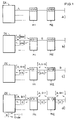
- FIG. 1 visualizes the addressing sequence of the peripheral modules M1 and M2 in a branch L to be addressed from the central unit ZE.
- This exemplary embodiment shows the simplest case of a BUS line structure, which, however, can be expanded by any number of modules, branches and / or rings. Since the central unit inevitably needs its own connection (I / O port) for each separate branch or ring, the central unit only needs to know the maximum possible number of modules per branch or ring be. However, this can practically be ensured at any time in that if the maximum number is exceeded, a branch or ring must be added accordingly. Of course, it is particularly advantageous if the central unit is informed of the exact structure of the BUS line system before addressing begins.
- the modules M1 and M2 are connected via the line L.
- the modules M1 and M2 are both set to the unit address [000] by default.
- Each module has two line sections, either to the central unit in the first module M1, to the neighboring modules or to the open or ring end, as shown in the second module.
- step a) the central unit ZE sends the addressing command A with the first addressing data word [001] on the line L, where it is received by the first module M1. Since M1 was not previously addressed, M1 now adopts the address [001] does not forward the addressing command, as represented by [0] in the following line section, and sends back a response [o.k.].
- step b) the central unit now sends its second addressing data word [010], which was generated by a counter incremented by one. In general, it makes sense to adhere to a strict sequence of address assignments, but it is not absolutely necessary.
- module M1 has already been addressed and now forwards the addressing command to the second module M2. Since this was previously unaddressed, it now takes over the second addressing data word, as visualized by changing the address memory content. As a result, the addressing command is not forwarded and a reply [o.k.] is sent back to the central unit ZE.
- step c) the central unit ZE sends the addressing data word [011], but this is now forwarded by both module M1 and module M2 becomes.
- the forwarding can be both a passive release of a switchable direct connection of the corresponding line sections, but can also take place actively by means of intermediate amplification and further transmission by means of active transmission devices.
- the forwarding of the addressing command from a previously unaddressed module can also be prevented in that it no longer amplifies or sends this command. Otherwise, appropriate switching means for suppressing the forwarding must be provided, which are set to continuity after the addressing.
- module M2 Since module M2 is the last module in branch L, there is no reply [o.k.], no signal is sent back. This is visualized by [0].
- the central unit ZE then recognizes that all modules in branch L are addressed and can now address another branch or ring and use the address again, or ends the addressing (end).
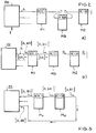
- FIG. 2 shows how a module M3 newly inserted into an already addressed BUS line system is addressed using the method according to the invention.
- Module M3 like all unaddressed modules, is previously assigned [000], and is now inserted between module M1 and module M2 in step a).
- the central unit now receives the information (I) that a new module has been inserted and triggers an addressing command with the next free address [011]. This is now taken over by module M3, not forwarded and the reply [o.k.] sent to the central unit. If necessary, the central unit checks the complete addressing of all modules via a further addressing attempt, as already shown in FIG. 1c).
- FIG. 3 illustrates that the addressing method described can also be used for ring structures, with several options for responding to the central unit, depending on the definition of the transmission paths as mono or bidirectional.
- the central unit can also recognize by receiving the unprocessed addressing command (see FIG. 3) that all modules are addressed, since all Modules have forwarded the addressing command.
- the individual modules can now optionally send certain identification characters to the central unit, whereby their technical character is recognized.
Landscapes
- Engineering & Computer Science (AREA)
- Physics & Mathematics (AREA)
- General Physics & Mathematics (AREA)
- Automation & Control Theory (AREA)
- Mechanical Engineering (AREA)
- Small-Scale Networks (AREA)
- Electric Propulsion And Braking For Vehicles (AREA)
Applications Claiming Priority (2)
| Application Number | Priority Date | Filing Date | Title |
|---|---|---|---|
| DE19619117 | 1996-05-11 | ||
| DE1996119117 DE19619117A1 (de) | 1996-05-11 | 1996-05-11 | Steuersystem, insbesondere für Sicherheitssysteme in Kraftfahrzeugen, und Verfahren zum Austauschen von Informationen in einem Steuersystem |
Publications (3)
| Publication Number | Publication Date |
|---|---|
| EP0807887A2 true EP0807887A2 (fr) | 1997-11-19 |
| EP0807887A3 EP0807887A3 (fr) | 2002-01-30 |
| EP0807887B1 EP0807887B1 (fr) | 2005-11-09 |
Family
ID=7794096
Family Applications (1)
| Application Number | Title | Priority Date | Filing Date |
|---|---|---|---|
| EP19970107341 Expired - Lifetime EP0807887B1 (fr) | 1996-05-11 | 1997-05-03 | Méthode d'adressage de plusieurs modules périphériques par une unité centrale dans une système de bus |
Country Status (2)
| Country | Link |
|---|---|
| EP (1) | EP0807887B1 (fr) |
| DE (2) | DE19619117A1 (fr) |
Cited By (4)
| Publication number | Priority date | Publication date | Assignee | Title |
|---|---|---|---|---|
| WO2003085465A1 (fr) * | 2002-04-05 | 2003-10-16 | Siemens Aktiengesellschaft | Procede de projection et/ou d'utilisation d'un systeme d'automatisation |
| DE102012106210A1 (de) * | 2012-07-10 | 2014-01-16 | Trinamic Motion Control Gmbh & Co. Kg | Verfahren zur seriellen Datenübertragung |
| DE102017000930B3 (de) * | 2016-05-02 | 2017-06-01 | Sew-Eurodrive Gmbh & Co Kg | Verfahren zur Integration eines weiteren Busteilnehmers in ein Bussystem und Bussystem |
| DE102024121677A1 (de) * | 2024-07-30 | 2026-02-05 | Valeo Schalter Und Sensoren Gmbh | Verfahren zum Konfigurieren eines Sensor-Systems mit einer Adressierung von Sensoren auf Basis eines spezifischen Adressierungssignals, sowie Fahrzeug-Sensor-System |
Families Citing this family (16)
| Publication number | Priority date | Publication date | Assignee | Title |
|---|---|---|---|---|
| DE19740021A1 (de) | 1997-09-11 | 1999-03-25 | Siemens Ag | Einrichtung für den Insassenschutz in einem Kraftfahrzeug |
| DE19813123A1 (de) * | 1998-03-25 | 1999-10-07 | Daimler Chrysler Ag | Insassenschutzsystem |
| DE19813954A1 (de) * | 1998-03-28 | 1999-05-27 | Telefunken Microelectron | Verfahren zum Programmieren von mittels einem BUS-Leitungssystem mit einer Zentraleinheit verbundenen Modulen |
| DE19813953C2 (de) | 1998-03-28 | 2000-06-08 | Telefunken Microelectron | Steuerverfahren und Modul für Insassenschutzsysteme, insbesondere in Kraftfahrzeugen |
| DE19813963A1 (de) * | 1998-03-28 | 1999-05-20 | Telefunken Microelectron | Sicherheitssystem in einem Personenbeförderungsmittel mit Steuermodulen für Insassenschutzeinrichtungen |
| DE19813957C2 (de) | 1998-03-28 | 2003-06-18 | Conti Temic Microelectronic | Insassenschutzsystem mit einer Zentraleinheit, Sensoren und mehreren mittels eines BUS-Systems kommunikationsfähig verbundenen Steuermodulen zur Auslösung von Insassenschutzeinrichtungen |
| DE19829756C1 (de) | 1998-07-03 | 2000-03-16 | Daimler Chrysler Ag | Auslösegerät für ein Insassenschutzsystem |
| DE19937151B4 (de) | 1999-08-06 | 2006-11-02 | Daimlerchrysler Ag | Aktives Insassenrückhaltesystem mit ring- und/oder stichförmiger Zündbusleitung |
| DE10063504A1 (de) * | 2000-12-20 | 2002-07-04 | Bayerische Motoren Werke Ag | Airbag-Steuergerät und Verfahren zur Airbag-Steuerung |
| DE10144829A1 (de) * | 2001-09-12 | 2003-03-27 | Valeo Schalter & Sensoren Gmbh | System zur Erfassung und Anzeige des Abstandes von Fahrzeugen zu Hindernissen sowie Stossfänger |
| DE10356753B4 (de) * | 2003-12-04 | 2006-10-05 | Bayerische Motoren Werke Ag | Verfahren und Vorrichtung zur Steuerung des Auslöseverhaltens eines pyrotechnischen Systems in einem Sicherheitssystem |
| DE102004040323A1 (de) * | 2004-08-20 | 2006-02-23 | Conti Temic Microelectronic Gmbh | Verfahren und Vorrichtung zur Erzeugung eines Plausibilisierungssignals für das Auslösen eines Insassenschutzsystems in einem Fahrzeug |
| DE102004043296A1 (de) * | 2004-09-08 | 2006-03-09 | Fendt, Günter | Sicherheitseinrichtung mit Rückhaltevorrichtungen für Omnibusse und Verfahren zum Aktivieren der Rückhaltevorrichtung einer Sicherheitseinrichtung für Omnibusse |
| DE102006057493B4 (de) * | 2006-12-06 | 2011-07-07 | Fendt, Günter, 86529 | Verfahren und Schaltungsanordnung in einem Kraftfahrzeug zur Erhöhung der Datenübertragungsrate und/oder der Datenübertragungssicherheit zwischen einem Sensor-Cluster und einer räumlich davon getrennten signalverarbeitenden Elektronik, mittels einer elektrischen Schnittstelle |
| DE102007005063A1 (de) | 2007-01-26 | 2008-07-31 | Conti Temic Microelectronic Gmbh | Verfahren zur Energieversorgung eines Sensors für ein Fahrzeugsteuersystem |
| DE102007005062A1 (de) | 2007-01-26 | 2008-07-31 | Conti Temic Microelectronic Gmbh | Verfahren zur Datenübertragung zwischen zumindest einem Sensor und einer Zentraleinheit eines Fahrzeugsteuergeräts |
Family Cites Families (11)
| Publication number | Priority date | Publication date | Assignee | Title |
|---|---|---|---|---|
| DE3340992A1 (de) * | 1983-11-12 | 1985-05-23 | Licentia Patent-Verwaltungs-Gmbh, 6000 Frankfurt | Digitales kommunikationssystem |
| JPS6390929A (ja) * | 1986-10-03 | 1988-04-21 | Omron Tateisi Electronics Co | 多重伝送装置 |
| DE3706325A1 (de) * | 1987-02-27 | 1988-09-08 | Phoenix Elekt | Steuer- und datennetzwerk |
| DE3736081A1 (de) * | 1987-10-24 | 1989-05-03 | Licentia Gmbh | Verfahren und vorrichtung zur adresseneinstellung von an einen bus angeschlossenen teilnehmern |
| EP0421471A1 (fr) * | 1989-10-06 | 1991-04-10 | Mütec Mikrotechnik Und Überwachungssysteme Gmbh | Méthode de communication pour un dispositif de commande constitué par une unité centrale et des unités périphériques |
| JPH03136157A (ja) * | 1989-10-23 | 1991-06-10 | Brother Ind Ltd | アドレス設定装置 |
| DE4133385A1 (de) * | 1991-10-09 | 1993-04-15 | Philips Patentverwaltung | Hierarchisches netzmanagementsystem |
| JP2848736B2 (ja) * | 1992-04-02 | 1999-01-20 | 三菱電機株式会社 | ネットワークシステム |
| DE4242438C2 (de) * | 1992-12-16 | 1995-04-06 | Magnetbahn Gmbh | Vorrichtung zur Ausnutzung der Redundanz bei Datenringen in Doppelringtopologie |
| DE4426466C2 (de) * | 1994-07-26 | 2002-06-20 | Siemens Ag | Anordnung und Verfahren zum Betreiben von Gefahrenmeldern |
| DE4428502A1 (de) * | 1994-08-11 | 1996-02-15 | Siemens Ag | Bussystem |
-
1996
- 1996-05-11 DE DE1996119117 patent/DE19619117A1/de not_active Ceased
-
1997
- 1997-05-03 EP EP19970107341 patent/EP0807887B1/fr not_active Expired - Lifetime
- 1997-05-03 DE DE59712470T patent/DE59712470D1/de not_active Expired - Fee Related
Cited By (10)
| Publication number | Priority date | Publication date | Assignee | Title |
|---|---|---|---|---|
| WO2003085465A1 (fr) * | 2002-04-05 | 2003-10-16 | Siemens Aktiengesellschaft | Procede de projection et/ou d'utilisation d'un systeme d'automatisation |
| US7185129B2 (en) | 2002-04-05 | 2007-02-27 | Siemens Aktiengesellschaft | Method for configuring and/or operating an automation device having a master unit connected to one or more slave units |
| DE102012106210A1 (de) * | 2012-07-10 | 2014-01-16 | Trinamic Motion Control Gmbh & Co. Kg | Verfahren zur seriellen Datenübertragung |
| DE102017000930B3 (de) * | 2016-05-02 | 2017-06-01 | Sew-Eurodrive Gmbh & Co Kg | Verfahren zur Integration eines weiteren Busteilnehmers in ein Bussystem und Bussystem |
| WO2017190842A1 (fr) | 2016-05-02 | 2017-11-09 | Sew-Eurodrive Gmbh & Co. Kg | Procédé d'intégration d'un autre abonné de bus dans un système de bus, et système de bus |
| US10572418B2 (en) | 2016-05-02 | 2020-02-25 | Sew-Eurodrive Gmbh & Co. Kg | Method for integrating a further bus subscriber into a bus system, and bus system for integrating a further bus subscriber therein |
| US10884963B2 (en) | 2016-05-02 | 2021-01-05 | Sew-Eurodrive Gmbh & Co. Kg | Method for integrating a further bus subscriber into a bus system, and bus system for integrating a further bus subscriber therein |
| US11487686B2 (en) | 2016-05-02 | 2022-11-01 | Sew-Eurodrive Gmbh & Co. Kg | Bus system and method for allocating addresses to a plurality of bus subscribers in a bus system |
| US11803495B2 (en) | 2016-05-02 | 2023-10-31 | Sew-Eurodrive Gmbh & Co. Kg | Method for allocating addresses to a plurality of bus subscribers in a bus system that includes a master module and bus system having a master module and a plurality of bus subscribers |
| DE102024121677A1 (de) * | 2024-07-30 | 2026-02-05 | Valeo Schalter Und Sensoren Gmbh | Verfahren zum Konfigurieren eines Sensor-Systems mit einer Adressierung von Sensoren auf Basis eines spezifischen Adressierungssignals, sowie Fahrzeug-Sensor-System |
Also Published As
| Publication number | Publication date |
|---|---|
| DE59712470D1 (de) | 2005-12-15 |
| EP0807887A3 (fr) | 2002-01-30 |
| DE19619117A1 (de) | 1997-11-13 |
| EP0807887B1 (fr) | 2005-11-09 |
Similar Documents
| Publication | Publication Date | Title |
|---|---|---|
| EP0807887B1 (fr) | Méthode d'adressage de plusieurs modules périphériques par une unité centrale dans une système de bus | |
| DE102007009042B4 (de) | Buskommunikationssystem | |
| DE19742716C5 (de) | Steuer- und Datenübertragungsanlage und Verfahren zum Übertragen von sicherheitsbezogenen Daten | |
| DE4110372C2 (de) | Multiplex-Übertragungssystem für Fahrzeuge | |
| EP1066176B1 (fr) | Procede de transfert de donnees dans un systeme de retenue interconnecte par une ligne de bus | |
| EP1068109B1 (fr) | Procede de transmission d'energie et de donnees dans un systeme de bus destine a des dispositifs de protection des occupants | |
| DE10022173A1 (de) | Verfahren zur Auslösung von Insassenschutzeinrichtungen | |
| DE69129510T2 (de) | Multiplex-Übertragungssystem für Kraftfahrzeuge | |
| EP2060459B1 (fr) | Agencement de freinage pour un véhicule sur rail et procédé destiné au freinage du véhicule sur rail et commande de frein pour un tel agencement de freinage | |
| DE19829842B4 (de) | System und Verfahren zur Kommunikation zwischen einer zentralen Einheit und einer Vielzahl entfernter bzw. entfernt gelegener Einheiten für ein Fahrzeuginsassen-Rückhaltesystem | |
| DE102015222545A1 (de) | Bordnetz | |
| WO2001024013A2 (fr) | Circuit de protection d'un reseau systeme a bus d'acces aleatoire | |
| EP0842824A1 (fr) | Procédé de contrÔle d'un système de sécurité dans un véhicule à moteur | |
| DE19922408B4 (de) | Bus-System mit bei Störungen automatisch abschaltbaren Teilnetzen | |
| EP1066175A1 (fr) | Procede de transfert de donnees dans un systeme de retenue connecte a une ligne de bus | |
| DE19702270C2 (de) | Verfahren zum Übertragen von Information in einem System, insbesondere in einem Sicherheitssystem für Kraftfahrzeuge | |
| EP2012469B1 (fr) | Procédé de fonctionnement d'un quasi-bus pour un système de protection des personnes, appareil de commande destiné à la commande d'un système de protection des personnes et dispositif de transmission de données de capteurs vers un appareil de commande destiné à la commande d'un système de protection des personnes par au moins un quasi-bus | |
| DE102008011165B4 (de) | Sensoranordnung für ein Insassenschutzsystem eines Kraftfahrzeugs | |
| DE102007058071A1 (de) | Verfahren und Vorrichtung zur Plausibilisierung einer Auswertung von sicherheitsrelevanten Signalen für ein Kraftfahrzeug | |
| DE102007038427B4 (de) | Airbag-System mit einem Schaltmodul zur Umschaltung des Signal- oder Versorgungspfades | |
| WO2002085676A1 (fr) | Systeme de bus de donnees pour capteurs d'un systeme de protection pour occupant d'une voiture | |
| DE19702271C2 (de) | Verfahren zum Übertragen von Daten in einem System, insbesondere in einem Sicherheitssystem für Kraftfahrzeuge | |
| DE19843074A1 (de) | Zündstromkreis für Auslösemittel passiver Insassenschutzeinrichtungen | |
| DE19702269B4 (de) | Verfahren zum Testen der Zuverlässigkeit der Informationsübertragung in einem System, insbesondere in einem Sicherheitssystem für Kraftfahrzeuge | |
| DE102017220870A1 (de) | Verfahren zur Überlastsicherung wenigstens einer Busstation in einem Kraftfahrzeug sowie Schaltungsanordnung zur Durchführung des Verfahrens |
Legal Events
| Date | Code | Title | Description |
|---|---|---|---|
| PUAI | Public reference made under article 153(3) epc to a published international application that has entered the european phase |
Free format text: ORIGINAL CODE: 0009012 |
|
| AK | Designated contracting states |
Kind code of ref document: A2 Designated state(s): DE ES FR GB IT SE |
|
| RAP1 | Party data changed (applicant data changed or rights of an application transferred) |
Owner name: TEMIC TELEFUNKEN MICROELECTRONIC GMBH |
|
| RAP1 | Party data changed (applicant data changed or rights of an application transferred) |
Owner name: CONTI TEMIC MICROELECTRONIC GMBH |
|
| PUAL | Search report despatched |
Free format text: ORIGINAL CODE: 0009013 |
|
| AK | Designated contracting states |
Kind code of ref document: A3 Designated state(s): DE ES FR GB IT SE |
|
| RIC1 | Information provided on ipc code assigned before grant |
Free format text: 7G 06F 13/37 A, 7G 05B 9/02 B |
|
| 17P | Request for examination filed |
Effective date: 20020327 |
|
| 17Q | First examination report despatched |
Effective date: 20030530 |
|
| GRAP | Despatch of communication of intention to grant a patent |
Free format text: ORIGINAL CODE: EPIDOSNIGR1 |
|
| GRAS | Grant fee paid |
Free format text: ORIGINAL CODE: EPIDOSNIGR3 |
|
| GRAA | (expected) grant |
Free format text: ORIGINAL CODE: 0009210 |
|
| AK | Designated contracting states |
Kind code of ref document: B1 Designated state(s): DE ES FR GB IT SE |
|
| PG25 | Lapsed in a contracting state [announced via postgrant information from national office to epo] |
Ref country code: IT Free format text: LAPSE BECAUSE OF FAILURE TO SUBMIT A TRANSLATION OF THE DESCRIPTION OR TO PAY THE FEE WITHIN THE PRE;WARNING: LAPSES OF ITALIAN PATENTS WITH EFFECTIVE DATE BEFORE 2007 MAY HAVE OCCURRED AT ANY TIME BEFORE 2007. THE CORRECT EFFECTIVE DATE MAY BE DIFFERENT FROM THE ONE RECORDED.SCRIBED TIME-LIMIT Effective date: 20051109 Ref country code: GB Free format text: LAPSE BECAUSE OF FAILURE TO SUBMIT A TRANSLATION OF THE DESCRIPTION OR TO PAY THE FEE WITHIN THE PRESCRIBED TIME-LIMIT Effective date: 20051109 |
|
| REG | Reference to a national code |
Ref country code: GB Ref legal event code: FG4D Free format text: NOT ENGLISH |
|
| REF | Corresponds to: |
Ref document number: 59712470 Country of ref document: DE Date of ref document: 20051215 Kind code of ref document: P |
|
| PG25 | Lapsed in a contracting state [announced via postgrant information from national office to epo] |
Ref country code: SE Free format text: LAPSE BECAUSE OF FAILURE TO SUBMIT A TRANSLATION OF THE DESCRIPTION OR TO PAY THE FEE WITHIN THE PRESCRIBED TIME-LIMIT Effective date: 20060209 |
|
| PG25 | Lapsed in a contracting state [announced via postgrant information from national office to epo] |
Ref country code: ES Free format text: LAPSE BECAUSE OF FAILURE TO SUBMIT A TRANSLATION OF THE DESCRIPTION OR TO PAY THE FEE WITHIN THE PRESCRIBED TIME-LIMIT Effective date: 20060220 |
|
| GBV | Gb: ep patent (uk) treated as always having been void in accordance with gb section 77(7)/1977 [no translation filed] |
Effective date: 20051109 |
|
| ET | Fr: translation filed | ||
| PLBE | No opposition filed within time limit |
Free format text: ORIGINAL CODE: 0009261 |
|
| STAA | Information on the status of an ep patent application or granted ep patent |
Free format text: STATUS: NO OPPOSITION FILED WITHIN TIME LIMIT |
|
| 26N | No opposition filed |
Effective date: 20060810 |
|
| PGFP | Annual fee paid to national office [announced via postgrant information from national office to epo] |
Ref country code: FR Payment date: 20090513 Year of fee payment: 13 Ref country code: DE Payment date: 20090525 Year of fee payment: 13 |
|
| REG | Reference to a national code |
Ref country code: FR Ref legal event code: ST Effective date: 20110131 |
|
| PG25 | Lapsed in a contracting state [announced via postgrant information from national office to epo] |
Ref country code: DE Free format text: LAPSE BECAUSE OF NON-PAYMENT OF DUE FEES Effective date: 20101201 |
|
| PG25 | Lapsed in a contracting state [announced via postgrant information from national office to epo] |
Ref country code: FR Free format text: LAPSE BECAUSE OF NON-PAYMENT OF DUE FEES Effective date: 20100531 |