EP0803463B1 - Schwelle für eine Aufzugstockwerktür - Google Patents
Schwelle für eine Aufzugstockwerktür Download PDFInfo
- Publication number
- EP0803463B1 EP0803463B1 EP97106326A EP97106326A EP0803463B1 EP 0803463 B1 EP0803463 B1 EP 0803463B1 EP 97106326 A EP97106326 A EP 97106326A EP 97106326 A EP97106326 A EP 97106326A EP 0803463 B1 EP0803463 B1 EP 0803463B1
- Authority
- EP
- European Patent Office
- Prior art keywords
- limb
- shaped
- landing
- channel
- threshold
- Prior art date
- Legal status (The legal status is an assumption and is not a legal conclusion. Google has not performed a legal analysis and makes no representation as to the accuracy of the status listed.)
- Expired - Lifetime
Links
- 239000000463 material Substances 0.000 claims description 5
- 229910000831 Steel Inorganic materials 0.000 claims description 3
- 230000015572 biosynthetic process Effects 0.000 claims description 3
- 239000010959 steel Substances 0.000 claims description 3
- XAGFODPZIPBFFR-UHFFFAOYSA-N aluminium Chemical compound [Al] XAGFODPZIPBFFR-UHFFFAOYSA-N 0.000 claims description 2
- 229910052782 aluminium Inorganic materials 0.000 claims description 2
- 239000004411 aluminium Substances 0.000 claims description 2
- 238000005266 casting Methods 0.000 claims description 2
- 230000000295 complement effect Effects 0.000 claims description 2
- 238000004873 anchoring Methods 0.000 claims 1
- 230000000149 penetrating effect Effects 0.000 claims 1
- 239000004568 cement Substances 0.000 description 1
- 238000010276 construction Methods 0.000 description 1
- 230000001419 dependent effect Effects 0.000 description 1
- 239000004570 mortar (masonry) Substances 0.000 description 1
- 238000005192 partition Methods 0.000 description 1
Images


Classifications
-
- B—PERFORMING OPERATIONS; TRANSPORTING
- B66—HOISTING; LIFTING; HAULING
- B66B—ELEVATORS; ESCALATORS OR MOVING WALKWAYS
- B66B13/00—Doors, gates, or other apparatus controlling access to, or exit from, cages or lift well landings
- B66B13/30—Constructional features of doors or gates
- B66B13/301—Details of door sills
Definitions
- the present invention relates to a threshold for a landing door for a lift shaft.
- a threshold for a landing door for a lift shaft according to the preamble of independent claim 1 is known from US-A-3 686 808.
- the object of the present invention is to provide a threshold for a landing door for a lift which has a simple, robust structure and which is easy to put into operation.
- a threshold 1 includes a support structure constituted by a plate 2 of steel having a sinuous transverse profile.
- the plate 2 has three raised portions 3, 4 and 5 between which are two longitudinally-extending channel-shaped portions 6 and 7 which are upwardly open.
- These channel-shaped portions have respective, essentially vertical walls 6a, 6b and 7a, 7b and respective bases 6c and 7c.
- the lower parts of the walls 6b and 7b of the channel-shaped portions 6 and 7 define respective lateral recesses indicated 6d and 7d respectively.
- the shaped plate 2 also has two substantially vertical edge portions or skirts 8 and 9.
- This profiled element has three raised portions 11, 12 and 13 between which are two channel portions 14 and 15 intended to serve as guides for running members, such as shoes or rollers, of two door panels (not illustrated).
- the profiled cover element 10 has an edge portion 16 bent downwardly.
- the profiled cover element 10 has a shape complementary to that of the support structure 2 so that said cover element 10 can be fitted to the support structure 2 so that the guide channels 14 and 15 penetrate the channel-shaped portions 6 and 7 of the support plate.
- the raised portions 11, 12 and 13 of the profiled cover element 10 rest on the corresponding raised portions 3, 4 and 5 of the steel plate 2.
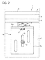
- each of the beam elements is of essentially channel section with the channel open downwardly (see Figure 2).
- the support plate 2 is connected to the beam elements 17 by connecting members such as screws, indicated 26 in Figure 1, located in the recesses 6d and 7d of the loops of this plate.
- the connecting members are obviously screwed in before the profiled cover element 10 is located on the support plate 2.
- Each beam element 17 is fixed to a horizontal limb 18a of an L-shaped bracket 18 by known connecting members such as a bolt 19 and associated nut or like female-thread element 20 (see in particular Figure 2).
- the other limb 18b of the bracket 18 is fixed to the wall W of the lift shaft S adjacent the lower edge of the door opening O, for example by means of a bolt 21 which passes through a slot 22 in the bracket.
- Each bracket 18 is fixed to the wall W of the lift shaft S at a level below the surface of the landing L ( Figure 1) close to the lower edge of the door opening O so that, in the assembled condition of the threshold, the upper surfaces of the profiled cover element 10 are substantially flush with the landing L.
- the threshold further includes a profiled trim element indicated 23 in Figure 1.
- this profiled trim element 23 has a substantially T-shaped cross-section with a first upper arm 23a which lies over a portion 13 of the profiled cover element 10 and a second arm or limb 23b which projects at least partly over the surface of the landing L, covering the space between the landing and the profiled cover element 10.
- the profiled trim element 23 also has an essentially vertical stem 23c located adjacent the vertical limb portion 9 of the support plate 2.
- the stem 23c of the trim element 23 has a bent lower edge portion 23d which engages beneath the edge of the vertical limb portion 9 of the support plate 2.
- the horizontal arm 23a of the trim element 23 has a downwardly-bent edge portion 23e with a tooth-shaped retaining formation 23f on its side facing the landing L which engages a cooperating groove 15a in the cover element 10.
- the trim element 23 is thus firmly connected to the cover element 10 and to the support plate 2. It may, however, easily be removed by slight resilient deformation to allow its bent lower edge 23d to be disengaged from the bottom edge of the edge portion 9 of the support plate 2 and then the toothed formation 23f to be removed from the groove 15a.
- the threshold described above with reference to Figures 1 and 2 is intended for use with a landing door for a lift in which the door has two door panels which run in the guide channels 14 and 15 of the profiled element 10.
- Figure 3 shows a variant of the threshold of the invention for a door having only one door panel indicated P.
- the support plate 2 forms a single channel-shaped portion indicated 6 and, correspondingly, the profiled cover element 10 forms a single guide channel 14.
- the threshold 1 further includes a profiled retaining element 24 (see also Figure 4) which has a horizontal limb 24a located on the plane of the landing L before the laying or casting of a layer 25 of material for covering the landing, such as mortar, cement.
- the limb 24a of the retaining element 24 is joined to a portion 24b of this profiled element which is essentially channel shaped and has a base interposed between the beam elements 17 and the associated support brackets 18.
- the limb 24a of the profiled element 24 when the limb 24a of the profiled element 24 is in its position of use, it is covered by the layer 25 of material which covers the landing L.
- Some of this material 25 may also be introduced into the channel portion 24b of this profiled element, extending as far as a vertical partition indicated 26 in Figure 3 which bears against the beam elements 17.
- the limb 23b of the profiled trim element 23 rests on the layer 25 which covers the landing L.
- a profiled retaining element 24 has been illustrated in a threshold with a single guide channel for the running of a door panel, obviously such a profiled retaining element may also be incorporated in a threshold with two or more guide channels, such as that described previously with reference to Figures 1 and 2.
Landscapes
- Elevator Door Apparatuses (AREA)
- Wing Frames And Configurations (AREA)
Claims (8)
- Schwelle (1) für eine Stockwerktür (P) eines Aufzugsschachts (S), umfassend eine Stützstruktur umfassendeine Platte (2) aus Stahl mit einem wellenartigen Profil, welche zumindest einen längsgerichteten, nach oben offenen, rinnenförmigen Abschnitt (6, 7) zwischen zwei erhöhten Abschnitten (3, 4; 4, 5) bildet;zumindest ein vorzugsweise aus Aluminium bestehendes, profiliertes Abdeckelement (10), wovon ein dazwischenliegender Abschnitt zumindest eine Führung (14, 15) zum Führen des Laufs einer Türfüllung (P) bildet;Fixierungseinrichtungen (17-22), welche bei Verwendung geeignet sind zum Verankern der Stützstruktur (2), angrenzend an die Zone, welche in der Nähe der Unterkante einer Türöffnung (O) das Stockwerk (L) mit dem Aufzugsschacht (S) verbindet, mit dem rinnenförmigen Abschnitt (6, 7) und der Führung (14, 15), welche bei Verwendung parallel zur Kante der Türöffnung (O) verfügbar sind, und mit der Oberfläche (11-13) des Abdeckelements (10), welche im Wesentlichen auf gleicher Ebene mit dem Stockwerk (L) liegt, wenn die Schwelle installiert wird, dadurch gekennzeichnet, dass das Abdeckelement (10) eine Form hat, welche zu jener der Stützstruktur (2) komplementär ist, so dass dieses Abdeckelement (10) an der Stützstruktur (2) befestigt werden kann, so dass die Führung (14, 15) in den entsprechenden rinnenförmigen Abschnitt (6, 7) der Stützstruktur (2) eindringt.
- Schwelle nach Anspruch 1, dadurch gekennzeichnet, dass die Platte (2) zwei längsgerichtete, parallele, nach oben offene, rinnenförmige Abschnitte (6, 7) besitzt, welche zwischen drei erhöhten Abschnitten (3-5) gebildet sind, und das Abdeckelement (10) demgemäß zwei Führungen (14, 15) für den Lauf der jeweiligen Türfüllungen (P) bildet, wobei die Führungen (14, 15) in die rinnenförmigen Abschnitte (6, 7) der Platte (2) eindringen.
- Schwelle nach Anspruch 1 oder Anspruch 2, dadurch gekennzeichnet, dass sie weiters ein profiliertes Deckelement (23) umfasst, welches an das Abdeckelement (10) gekoppelt ist und zumindest ein vorragendes Glied (23b) besitzt, welches bei Installierung der Schwelle (1) zumindest teilweise über der Oberfläche des Stockwerks (L) herausragt, wobei es den Raum zwischen dem Stockwerk (L) und dem Abdeckelement (10) bedeckt.
- Schwelle nach Anspruch 3, dadurch gekennzeichnet, dass das profilierte Deckelement (23) einen im Wesentlichen T-förmigen Querschnitt mit einem ersten oberen Arm (23a), welcher über einem Kantenabschnitt (13) des Abdeckelements (10) liegt, und einem zweiten oberen Arm (23b), welcher das vorragende Glied bildet, besitzt, wobei das vertikale Glied (23c) des profilierten Deckelements (23) an einem entprechenden vertikalen Glied (9) der geformten Stützplatte (2) angrenzt und einen gebogenen Fortsatz (23d) besitzt, welcher unter der Kante des vertikalen Glieds (9) der geformten Stützplatte (2) einrastet; wobei der erste obere Arm (23a) des profilierten Deckelements (23) einen nach unten gebogenen Kantenabschnitt (23e) mit einer gezahnten Haltestruktur (23f), welche in eine Rille (15a) im profilierten Abdeckelement (10) eingreift, besitzt.
- Schwelle nach einem der vorhergehenden Ansprüche, dadurch gekennzeichnet, dass zumindest ein rinnenförmiger Abschnitt (6, 7) der geformten Stützplatte (2) eine seitliche Vertiefung (6d, 7d) in einer im Wesentlichen vertikalen Wand (6b, 7b) hat, welche einen Raum bildet, welcher während des Zusammenbaus die Einführung und Inbetriebnahme von Verbindungsgliedern (26), wie Schrauben und Bolzen, zum Verbinden der Stützplatte (2) mit den Fixierungseinrichtungen (17, 18) ermöglicht.
- Schwelle nach einem der vorhergehenden Ansprüche, dadurch gekennzeichnet, dass die Fixierungseinrichtungen eine Mehrzahl von L-förmigen Trägern (18) umfassen, von denen jeder ein Glied (18a) besitzt, welches sich im zusammengebauten Zustand horizontal erstreckt, und ein anderes Glied (18b), welches bei Verwendung in vertikaler Stellung an der Wand (W) des Aufzugsschachts oder des Aufzugraumes (S) befestigt wird, und
eine entsprechende Mehrzahl von Balkenelementen (17), von denen jedes am horizontalen Glied (18a) eines jeweiligen L-förmigen Trägers (18) befestigt ist und an denen die geformte Stützplatte (2) befestigt ist. - Schwelle nach Anspruch 6, dadurch gekennzeichnet, dass die Balkenelemente (17) Rinnenabschnitte mit nach unten gerichteter Rinne haben.
- Schwelle nach Anspruch 6 oder Anspruch 7, dadurch gekennzeichnet, dass sie weiters ein profiliertes Halteelement (24) mit einem horizontalen Glied (24a) zum Setzen bei Verwendung auf der Ebene des Stockwerks (L) vor dem Auflegen oder Gießen einer Schicht (25) aus einem Material zum Bedecken des Stockwerks (L) umfasst; wobei das Halteelement (24) im Wesentlichen eine an das Glied (24a) angrenzende Rinne (24b) bildet, deren Grundfläche zwischen den Balkenelementen (17) und den in Verbindung stehenden, L-förmigen Trägern (18) zwischengeschaltet ist; wobei das Glied (24a) des Halteelements (24) dazu bestimmt ist, von der Schicht (25) aus dem Material zum Bedecken des Stockwerks (L) bedeckt zu sein; wobei das profilierte Deckelement (23) der Schwelle (1) auf dieser Schicht (25) aufliegt.
Applications Claiming Priority (2)
| Application Number | Priority Date | Filing Date | Title |
|---|---|---|---|
| ITTO960320 | 1996-04-22 | ||
| IT96TO000320A IT1285848B1 (it) | 1996-04-22 | 1996-04-22 | Soglia per una porta di pianerottolo per un elevatore. |
Publications (2)
| Publication Number | Publication Date |
|---|---|
| EP0803463A1 EP0803463A1 (de) | 1997-10-29 |
| EP0803463B1 true EP0803463B1 (de) | 2002-06-12 |
Family
ID=11414573
Family Applications (1)
| Application Number | Title | Priority Date | Filing Date |
|---|---|---|---|
| EP97106326A Expired - Lifetime EP0803463B1 (de) | 1996-04-22 | 1997-04-17 | Schwelle für eine Aufzugstockwerktür |
Country Status (8)
| Country | Link |
|---|---|
| US (1) | US5915501A (de) |
| EP (1) | EP0803463B1 (de) |
| JP (1) | JPH1045361A (de) |
| CN (1) | CN1079075C (de) |
| CA (1) | CA2203288C (de) |
| DE (1) | DE69713204T2 (de) |
| ES (1) | ES2176550T3 (de) |
| IT (1) | IT1285848B1 (de) |
Cited By (2)
| Publication number | Priority date | Publication date | Assignee | Title |
|---|---|---|---|---|
| DE202011105571U1 (de) | 2011-09-09 | 2012-12-12 | Elevator Trading Gmbh | Türschwellenkörper für eine Schiebetür |
| CN104118789A (zh) * | 2014-07-22 | 2014-10-29 | 苏州市华威电梯部件有限公司 | 一种m型复合防脱铝地坎组件 |
Families Citing this family (27)
| Publication number | Priority date | Publication date | Assignee | Title |
|---|---|---|---|---|
| US6938380B2 (en) * | 2001-12-14 | 2005-09-06 | Harold S. Friedman | Elevator entrance sill structure and installation method |
| GB2387164B (en) * | 2002-04-04 | 2005-08-24 | Sematic Italia Spa | Footplate for use in lifts |
| EP1445410B1 (de) * | 2003-01-14 | 2006-07-19 | ThyssenKrupp Aufzugswerke GmbH | Schwelle für Aufzuganlage |
| DE10333086A1 (de) * | 2003-07-21 | 2005-02-17 | Wittur Ag | Abweisende Türpaneelführung |
| US7082725B2 (en) * | 2003-09-15 | 2006-08-01 | James Edward Visser | Threshold tray and clip system |
| KR100768247B1 (ko) | 2007-01-08 | 2007-10-17 | 주식회사 새한특수엘리베이터 | 엘리베이터 도어 실 보호커버 |
| ES2331382T3 (es) * | 2007-03-23 | 2009-12-30 | Wittur Holding Gmbh | Umbral con guia cubierta. |
| CN102951530A (zh) * | 2011-08-25 | 2013-03-06 | 康力电梯股份有限公司 | 一种层门地坎装置 |
| EP2913468B1 (de) * | 2014-02-28 | 2017-04-19 | Terno Scorrevoli S.p.A. Unipersonale | Vorrichtung zum mechanischen und automatischen Schließen von Schiebetüren |
| CN103879865A (zh) * | 2014-03-13 | 2014-06-25 | 苏州市华威电梯部件有限公司 | 一种m型复合地坎组件 |
| CN103879863A (zh) * | 2014-03-13 | 2014-06-25 | 苏州市华威电梯部件有限公司 | 一种s型复合地坎组件 |
| CN103935872A (zh) * | 2014-03-13 | 2014-07-23 | 苏州市华威电梯部件有限公司 | 一种货梯双槽铁地坎 |
| WO2015186189A1 (ja) * | 2014-06-03 | 2015-12-10 | 三菱電機株式会社 | エレベータの敷居 |
| CN104129700A (zh) * | 2014-07-22 | 2014-11-05 | 苏州市华威电梯部件有限公司 | 一种m型复合防脱不锈钢地坎组件 |
| US9873595B2 (en) * | 2014-11-20 | 2018-01-23 | Scott Akin | Elevator sill system |
| EP3224184B1 (de) * | 2014-11-27 | 2019-04-03 | SEMATIC S.p.A. | Verfahren zur herstellung einer schwelle für eine aufzugstür und schwelle |
| US20190093418A1 (en) * | 2016-08-01 | 2019-03-28 | Rodney Kim Ferris | Protect a track |
| JP6768630B2 (ja) * | 2017-12-15 | 2020-10-14 | 株式会社日立ビルシステム | エレベーター装置 |
| IT201900001073A1 (it) * | 2019-01-24 | 2020-07-24 | Wittur Holding Gmbh | Soglia per porta di ascensore |
| JP7140918B2 (ja) * | 2019-06-04 | 2022-09-21 | 株式会社日立製作所 | エレベータの乗場敷居装置 |
| BR112022000897A2 (pt) * | 2019-07-22 | 2022-05-17 | Inventio Ag | Dispositivo de segurança para a segurança de uma posição de um suporte angular de um umbral de porta de caixa de uma caixa de elevador, suporte angular e placa de segurança equipados com isso, bem como processo para reequipagem de tal placa de segurança |
| WO2022104084A1 (en) * | 2020-11-12 | 2022-05-19 | Nationwide Architectural Metals Inc. | Modular sills for elevators and methods of assembling the same |
| EP4255840B1 (de) * | 2020-12-01 | 2024-11-20 | Inventio Ag | Aufzugsystem mit einem montagebügel |
| WO2022139133A1 (ko) * | 2020-12-23 | 2022-06-30 | 장종철 | 도어 실 교체가 용이한 승강기용 승강장 및 그 시공방법 |
| JP7578034B2 (ja) * | 2021-03-24 | 2024-11-06 | 三菱電機株式会社 | エレベータの乗場敷居装置 |
| CN119317589A (zh) * | 2022-06-08 | 2025-01-14 | 因温特奥股份公司 | 电梯系统 |
| PL4568914T3 (pl) | 2023-10-09 | 2026-03-30 | Wittur Holding Gmbh | Próg do drzwi windy |
Family Cites Families (16)
| Publication number | Priority date | Publication date | Assignee | Title |
|---|---|---|---|---|
| US3584417A (en) * | 1969-03-17 | 1971-06-15 | Streater Ind Inc | Removable sliding-door track |
| US3703788A (en) * | 1970-10-01 | 1972-11-28 | Pemko Mfg Co | Automatic door bottom |
| US3686808A (en) * | 1971-03-15 | 1972-08-29 | Charles M Loomis | Door frame, sill and facia construction for elevator |
| CH550929A (de) * | 1972-04-27 | 1974-06-28 | Milster John | Zwischen fensterrahmen und mauerwerk anzuordnen bestimmte abschlussleiste. |
| US3805450A (en) * | 1972-10-25 | 1974-04-23 | Victor Metal Mfg Corp | Three section gravity door |
| US4781270A (en) * | 1987-03-02 | 1988-11-01 | Delaware Capital Formation, Inc. | Elevator door arrangement |
| JPH02188390A (ja) * | 1989-01-17 | 1990-07-24 | Hitachi Ltd | エレベータ出入口ドア装置 |
| JP2614326B2 (ja) * | 1989-07-31 | 1997-05-28 | 株式会社東芝 | エレベータの乗場装置 |
| DE59104217D1 (de) * | 1990-08-14 | 1995-02-23 | Inventio Ag | Glastürflügel für Aufzüge. |
| JPH0517091A (ja) * | 1991-07-12 | 1993-01-26 | Hitachi Ltd | エレベータの三方枠固定装置 |
| JP2516293B2 (ja) * | 1991-09-24 | 1996-07-24 | 三菱電機株式会社 | エレベ―タ乗場の敷居装置 |
| EP0548486B1 (de) * | 1991-12-24 | 1996-09-25 | Inventio Ag | Brandsichere Schachttür für Aufzugsanlagen |
| JP2713013B2 (ja) * | 1992-03-27 | 1998-02-16 | 三菱電機株式会社 | エレベーター用敷居の取付構造 |
| US5305855A (en) * | 1993-03-25 | 1994-04-26 | Otis Elevator Company | Sealed elevator cab entrance assembly |
| US5469666A (en) * | 1994-09-13 | 1995-11-28 | Lewis, Jr.; William P. | Walkable secure patio door threshold |
| FI101064B (fi) * | 1996-05-28 | 1998-04-15 | Kone Oy | Hissikorin kynnysjärjestely |
-
1996
- 1996-04-22 IT IT96TO000320A patent/IT1285848B1/it active IP Right Grant
-
1997
- 1997-04-04 CN CN97110320A patent/CN1079075C/zh not_active Expired - Lifetime
- 1997-04-17 ES ES97106326T patent/ES2176550T3/es not_active Expired - Lifetime
- 1997-04-17 DE DE69713204T patent/DE69713204T2/de not_active Expired - Lifetime
- 1997-04-17 EP EP97106326A patent/EP0803463B1/de not_active Expired - Lifetime
- 1997-04-21 CA CA002203288A patent/CA2203288C/en not_active Expired - Lifetime
- 1997-04-22 JP JP9117411A patent/JPH1045361A/ja active Pending
- 1997-04-22 US US08/844,881 patent/US5915501A/en not_active Expired - Lifetime
Cited By (2)
| Publication number | Priority date | Publication date | Assignee | Title |
|---|---|---|---|---|
| DE202011105571U1 (de) | 2011-09-09 | 2012-12-12 | Elevator Trading Gmbh | Türschwellenkörper für eine Schiebetür |
| CN104118789A (zh) * | 2014-07-22 | 2014-10-29 | 苏州市华威电梯部件有限公司 | 一种m型复合防脱铝地坎组件 |
Also Published As
| Publication number | Publication date |
|---|---|
| ES2176550T3 (es) | 2002-12-01 |
| US5915501A (en) | 1999-06-29 |
| CA2203288A1 (en) | 1997-10-22 |
| EP0803463A1 (de) | 1997-10-29 |
| DE69713204T2 (de) | 2003-02-20 |
| IT1285848B1 (it) | 1998-06-24 |
| CA2203288C (en) | 2004-02-10 |
| CN1167075A (zh) | 1997-12-10 |
| DE69713204D1 (de) | 2002-07-18 |
| ITTO960320A0 (it) | 1996-04-22 |
| JPH1045361A (ja) | 1998-02-17 |
| CN1079075C (zh) | 2002-02-13 |
| ITTO960320A1 (it) | 1997-10-22 |
Similar Documents
| Publication | Publication Date | Title |
|---|---|---|
| EP0803463B1 (de) | Schwelle für eine Aufzugstockwerktür | |
| AU718959B2 (en) | Door sill arrangement in an elevator car | |
| JPH1045361A5 (de) | ||
| US4879858A (en) | Method of installing a bathing vessel | |
| US11498812B2 (en) | Elevator landing door assembly and its installation method | |
| RU2395445C2 (ru) | Порог с закрытой направляющей | |
| US3262238A (en) | Elevated tile-stop member for adjustable electrical trench | |
| DE59712358D1 (de) | Abschlussprofil für mit Fliesen verlegte Balkone, Terrassen o.dgl. | |
| US4769948A (en) | Cavity mounted door construction | |
| US3452500A (en) | Wall paneling system | |
| US5383240A (en) | Adjustable trim strips for bathroom fixtures | |
| FI103030B (fi) | Ovikehysjärjestelmä hissin kerrostaso-ovea varten | |
| US20200291649A1 (en) | Thermally separated composite material | |
| JPH02273B2 (de) | ||
| JP3428784B2 (ja) | ドア構造およびその施工方法 | |
| JPH0113715Y2 (de) | ||
| JPH0318591A (ja) | エレベータ乗場の敷居 | |
| JP2609324B2 (ja) | エレベータ出入口装置 | |
| JP4391196B2 (ja) | エレベータ乗場の敷居装置 | |
| GB2254088A (en) | Floating floor | |
| JP2560027Y2 (ja) | 防水パンの設置構造 | |
| JPH0330497Y2 (de) | ||
| JPH05330767A (ja) | エレベータのかご室 | |
| GB2259314A (en) | Floor assembly | |
| JPH01303287A (ja) | エレベーターのドア装置 |
Legal Events
| Date | Code | Title | Description |
|---|---|---|---|
| PUAI | Public reference made under article 153(3) epc to a published international application that has entered the european phase |
Free format text: ORIGINAL CODE: 0009012 |
|
| AK | Designated contracting states |
Kind code of ref document: A1 Designated state(s): DE ES FR IT |
|
| 17P | Request for examination filed |
Effective date: 19980403 |
|
| RAP1 | Party data changed (applicant data changed or rights of an application transferred) |
Owner name: KONE CORPORATION |
|
| GRAG | Despatch of communication of intention to grant |
Free format text: ORIGINAL CODE: EPIDOS AGRA |
|
| 17Q | First examination report despatched |
Effective date: 20010716 |
|
| GRAG | Despatch of communication of intention to grant |
Free format text: ORIGINAL CODE: EPIDOS AGRA |
|
| GRAH | Despatch of communication of intention to grant a patent |
Free format text: ORIGINAL CODE: EPIDOS IGRA |
|
| GRAH | Despatch of communication of intention to grant a patent |
Free format text: ORIGINAL CODE: EPIDOS IGRA |
|
| GRAA | (expected) grant |
Free format text: ORIGINAL CODE: 0009210 |
|
| AK | Designated contracting states |
Kind code of ref document: B1 Designated state(s): DE ES FR IT |
|
| REF | Corresponds to: |
Ref document number: 69713204 Country of ref document: DE Date of ref document: 20020718 |
|
| ET | Fr: translation filed | ||
| REG | Reference to a national code |
Ref country code: ES Ref legal event code: FG2A Ref document number: 2176550 Country of ref document: ES Kind code of ref document: T3 |
|
| PLBE | No opposition filed within time limit |
Free format text: ORIGINAL CODE: 0009261 |
|
| STAA | Information on the status of an ep patent application or granted ep patent |
Free format text: STATUS: NO OPPOSITION FILED WITHIN TIME LIMIT |
|
| 26N | No opposition filed |
Effective date: 20030313 |
|
| REG | Reference to a national code |
Ref country code: FR Ref legal event code: PLFP Year of fee payment: 19 |
|
| REG | Reference to a national code |
Ref country code: FR Ref legal event code: PLFP Year of fee payment: 20 |
|
| PGFP | Annual fee paid to national office [announced via postgrant information from national office to epo] |
Ref country code: ES Payment date: 20160413 Year of fee payment: 20 Ref country code: DE Payment date: 20160421 Year of fee payment: 20 |
|
| PGFP | Annual fee paid to national office [announced via postgrant information from national office to epo] |
Ref country code: FR Payment date: 20160421 Year of fee payment: 20 Ref country code: IT Payment date: 20160426 Year of fee payment: 20 |
|
| REG | Reference to a national code |
Ref country code: DE Ref legal event code: R071 Ref document number: 69713204 Country of ref document: DE |
|
| REG | Reference to a national code |
Ref country code: ES Ref legal event code: FD2A Effective date: 20170726 |
|
| PG25 | Lapsed in a contracting state [announced via postgrant information from national office to epo] |
Ref country code: ES Free format text: LAPSE BECAUSE OF EXPIRATION OF PROTECTION Effective date: 20170418 |