EP0803463B1 - A threshold for a landing door for a lift - Google Patents
A threshold for a landing door for a lift Download PDFInfo
- Publication number
- EP0803463B1 EP0803463B1 EP97106326A EP97106326A EP0803463B1 EP 0803463 B1 EP0803463 B1 EP 0803463B1 EP 97106326 A EP97106326 A EP 97106326A EP 97106326 A EP97106326 A EP 97106326A EP 0803463 B1 EP0803463 B1 EP 0803463B1
- Authority
- EP
- European Patent Office
- Prior art keywords
- limb
- shaped
- landing
- channel
- threshold
- Prior art date
- Legal status (The legal status is an assumption and is not a legal conclusion. Google has not performed a legal analysis and makes no representation as to the accuracy of the status listed.)
- Expired - Lifetime
Links
Images


Classifications
-
- B—PERFORMING OPERATIONS; TRANSPORTING
- B66—HOISTING; LIFTING; HAULING
- B66B—ELEVATORS; ESCALATORS OR MOVING WALKWAYS
- B66B13/00—Doors, gates, or other apparatus controlling access to, or exit from, cages or lift well landings
- B66B13/30—Constructional features of doors or gates
- B66B13/301—Details of door sills
Definitions
- the present invention relates to a threshold for a landing door for a lift shaft.
- a threshold for a landing door for a lift shaft according to the preamble of independent claim 1 is known from US-A-3 686 808.
- the object of the present invention is to provide a threshold for a landing door for a lift which has a simple, robust structure and which is easy to put into operation.
- a threshold 1 includes a support structure constituted by a plate 2 of steel having a sinuous transverse profile.
- the plate 2 has three raised portions 3, 4 and 5 between which are two longitudinally-extending channel-shaped portions 6 and 7 which are upwardly open.
- These channel-shaped portions have respective, essentially vertical walls 6a, 6b and 7a, 7b and respective bases 6c and 7c.
- the lower parts of the walls 6b and 7b of the channel-shaped portions 6 and 7 define respective lateral recesses indicated 6d and 7d respectively.
- the shaped plate 2 also has two substantially vertical edge portions or skirts 8 and 9.
- This profiled element has three raised portions 11, 12 and 13 between which are two channel portions 14 and 15 intended to serve as guides for running members, such as shoes or rollers, of two door panels (not illustrated).
- the profiled cover element 10 has an edge portion 16 bent downwardly.
- the profiled cover element 10 has a shape complementary to that of the support structure 2 so that said cover element 10 can be fitted to the support structure 2 so that the guide channels 14 and 15 penetrate the channel-shaped portions 6 and 7 of the support plate.
- the raised portions 11, 12 and 13 of the profiled cover element 10 rest on the corresponding raised portions 3, 4 and 5 of the steel plate 2.
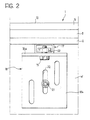
- each of the beam elements is of essentially channel section with the channel open downwardly (see Figure 2).
- the support plate 2 is connected to the beam elements 17 by connecting members such as screws, indicated 26 in Figure 1, located in the recesses 6d and 7d of the loops of this plate.
- the connecting members are obviously screwed in before the profiled cover element 10 is located on the support plate 2.
- Each beam element 17 is fixed to a horizontal limb 18a of an L-shaped bracket 18 by known connecting members such as a bolt 19 and associated nut or like female-thread element 20 (see in particular Figure 2).
- the other limb 18b of the bracket 18 is fixed to the wall W of the lift shaft S adjacent the lower edge of the door opening O, for example by means of a bolt 21 which passes through a slot 22 in the bracket.
- Each bracket 18 is fixed to the wall W of the lift shaft S at a level below the surface of the landing L ( Figure 1) close to the lower edge of the door opening O so that, in the assembled condition of the threshold, the upper surfaces of the profiled cover element 10 are substantially flush with the landing L.
- the threshold further includes a profiled trim element indicated 23 in Figure 1.
- this profiled trim element 23 has a substantially T-shaped cross-section with a first upper arm 23a which lies over a portion 13 of the profiled cover element 10 and a second arm or limb 23b which projects at least partly over the surface of the landing L, covering the space between the landing and the profiled cover element 10.
- the profiled trim element 23 also has an essentially vertical stem 23c located adjacent the vertical limb portion 9 of the support plate 2.
- the stem 23c of the trim element 23 has a bent lower edge portion 23d which engages beneath the edge of the vertical limb portion 9 of the support plate 2.
- the horizontal arm 23a of the trim element 23 has a downwardly-bent edge portion 23e with a tooth-shaped retaining formation 23f on its side facing the landing L which engages a cooperating groove 15a in the cover element 10.
- the trim element 23 is thus firmly connected to the cover element 10 and to the support plate 2. It may, however, easily be removed by slight resilient deformation to allow its bent lower edge 23d to be disengaged from the bottom edge of the edge portion 9 of the support plate 2 and then the toothed formation 23f to be removed from the groove 15a.
- the threshold described above with reference to Figures 1 and 2 is intended for use with a landing door for a lift in which the door has two door panels which run in the guide channels 14 and 15 of the profiled element 10.
- Figure 3 shows a variant of the threshold of the invention for a door having only one door panel indicated P.
- the support plate 2 forms a single channel-shaped portion indicated 6 and, correspondingly, the profiled cover element 10 forms a single guide channel 14.
- the threshold 1 further includes a profiled retaining element 24 (see also Figure 4) which has a horizontal limb 24a located on the plane of the landing L before the laying or casting of a layer 25 of material for covering the landing, such as mortar, cement.
- the limb 24a of the retaining element 24 is joined to a portion 24b of this profiled element which is essentially channel shaped and has a base interposed between the beam elements 17 and the associated support brackets 18.
- the limb 24a of the profiled element 24 when the limb 24a of the profiled element 24 is in its position of use, it is covered by the layer 25 of material which covers the landing L.
- Some of this material 25 may also be introduced into the channel portion 24b of this profiled element, extending as far as a vertical partition indicated 26 in Figure 3 which bears against the beam elements 17.
- the limb 23b of the profiled trim element 23 rests on the layer 25 which covers the landing L.
- a profiled retaining element 24 has been illustrated in a threshold with a single guide channel for the running of a door panel, obviously such a profiled retaining element may also be incorporated in a threshold with two or more guide channels, such as that described previously with reference to Figures 1 and 2.
Landscapes
- Elevator Door Apparatuses (AREA)
- Wing Frames And Configurations (AREA)
Description
- The present invention relates to a threshold for a landing door for a lift shaft.
- A threshold for a landing door for a lift shaft according to the preamble of
independent claim 1 is known from US-A-3 686 808. - The object of the present invention is to provide a threshold for a landing door for a lift which has a simple, robust structure and which is easy to put into operation.
- This object is achieved according to the invention by a threshold as defined in
independent claim 1. - Preferred embodiments are set out in the dependent claims.
- Further characteristics and advantages of the invention will become apparent from the detailed description which follows, given purely by way of non-limitative example, with reference to the appended drawings, in which:
- Figure 1 is a partially-sectioned side view of a threshold according to the invention shown in the assembled condition;
- Figure 2 is a partial view taken on the arrow II of Figure 1;
- Figure 3 shows a variant of the threshold according to the invention; and
- Figure 4 is a perspective view showing a profiled retaining element forming part of the threshold of Figure 3.
-
- With reference to Figure 1, a
threshold 1 according to the invention includes a support structure constituted by aplate 2 of steel having a sinuous transverse profile. - In the embodiment illustrated, the
plate 2 has three raisedportions shaped portions 6 and 7 which are upwardly open. These channel-shaped portions have respective, essentiallyvertical walls 6a, 6b and 7a, 7b and respective bases 6c and 7c. - The lower parts of the
walls 6b and 7b of the channel-shaped portions 6 and 7 define respective lateral recesses indicated 6d and 7d respectively. - The
shaped plate 2 also has two substantially vertical edge portions orskirts 8 and 9. - A profiled cover element indicated 10, preferably of aluminium, is located on the
shaped support plate 2. This profiled element has three raisedportions channel portions - The profiled
cover element 10 has anedge portion 16 bent downwardly. - As seen in Figure 1, the profiled
cover element 10 has a shape complementary to that of thesupport structure 2 so that saidcover element 10 can be fitted to thesupport structure 2 so that theguide channels shaped portions 6 and 7 of the support plate. The raisedportions cover element 10 rest on the corresponding raisedportions steel plate 2. - The
support plate 2 is fixed to a plurality of beam elements of which only one is visible in Figures 1 and 2 where it is indicated 17. In the embodiment illustrated by way of example, each of the beam elements is of essentially channel section with the channel open downwardly (see Figure 2). - Conveniently the
support plate 2 is connected to thebeam elements 17 by connecting members such as screws, indicated 26 in Figure 1, located in therecesses 6d and 7d of the loops of this plate. The connecting members are obviously screwed in before the profiledcover element 10 is located on thesupport plate 2. - Each
beam element 17 is fixed to ahorizontal limb 18a of an L-shaped bracket 18 by known connecting members such as abolt 19 and associated nut or like female-thread element 20 (see in particular Figure 2). - The
other limb 18b of thebracket 18 is fixed to the wall W of the lift shaft S adjacent the lower edge of the door opening O, for example by means of abolt 21 which passes through aslot 22 in the bracket. - Each
bracket 18 is fixed to the wall W of the lift shaft S at a level below the surface of the landing L (Figure 1) close to the lower edge of the door opening O so that, in the assembled condition of the threshold, the upper surfaces of the profiledcover element 10 are substantially flush with the landing L. - Conveniently the threshold further includes a profiled trim element indicated 23 in Figure 1. In the embodiment illustrated by way of example, this profiled
trim element 23 has a substantially T-shaped cross-section with a firstupper arm 23a which lies over aportion 13 of the profiledcover element 10 and a second arm orlimb 23b which projects at least partly over the surface of the landing L, covering the space between the landing and the profiledcover element 10. - The profiled
trim element 23 also has an essentiallyvertical stem 23c located adjacent the vertical limb portion 9 of thesupport plate 2. Thestem 23c of thetrim element 23 has a bentlower edge portion 23d which engages beneath the edge of the vertical limb portion 9 of thesupport plate 2. - The
horizontal arm 23a of thetrim element 23 has a downwardly-bent edge portion 23e with a tooth-shaped retaining formation 23f on its side facing the landing L which engages acooperating groove 15a in thecover element 10. Thetrim element 23 is thus firmly connected to thecover element 10 and to thesupport plate 2. It may, however, easily be removed by slight resilient deformation to allow its bentlower edge 23d to be disengaged from the bottom edge of the edge portion 9 of thesupport plate 2 and then thetoothed formation 23f to be removed from thegroove 15a. - The threshold described above with reference to Figures 1 and 2 is intended for use with a landing door for a lift in which the door has two door panels which run in the
guide channels element 10. - Figure 3 shows a variant of the threshold of the invention for a door having only one door panel indicated P. For this purpose the
support plate 2 forms a single channel-shaped portion indicated 6 and, correspondingly, the profiledcover element 10 forms asingle guide channel 14. - In the embodiment of Figure 3, the
threshold 1 further includes a profiled retaining element 24 (see also Figure 4) which has ahorizontal limb 24a located on the plane of the landing L before the laying or casting of alayer 25 of material for covering the landing, such as mortar, cement. Thelimb 24a of theretaining element 24 is joined to aportion 24b of this profiled element which is essentially channel shaped and has a base interposed between thebeam elements 17 and theassociated support brackets 18. As seen in Figure 3, when thelimb 24a of the profiledelement 24 is in its position of use, it is covered by thelayer 25 of material which covers the landing L. Some of thismaterial 25 may also be introduced into thechannel portion 24b of this profiled element, extending as far as a vertical partition indicated 26 in Figure 3 which bears against thebeam elements 17. - The
limb 23b of the profiledtrim element 23 rests on thelayer 25 which covers the landing L. - Although the use of a profiled
retaining element 24 has been illustrated in a threshold with a single guide channel for the running of a door panel, obviously such a profiled retaining element may also be incorporated in a threshold with two or more guide channels, such as that described previously with reference to Figures 1 and 2. - Naturally, the principle of the invention remaining the same, the forms of embodiment and details of construction may be varied widely with respect to those described and illustrated purely by way of non-limitative example, without thereby departing from the scope of the present invention as defined in the attached Claims.
Claims (8)
- A threshold (1) for a landing door (P) of a lift shaft (S), includinga support structure including a plate (2) of steel having a sinuous profile which forms at least one longitudinal, upwardly open channel-shaped portion (6, 7) between two raised portions (3, 4; 4, 5);at least one profiled cover element (10), preferably of aluminium, an intermediate portion whereof forms at least one guide (14, 15) for guiding the running of a door panel (P); andfixing means (17-22) which in use are suitable for anchoring the support structure (2) adjacent the zone connecting the landing (L) to the lift shaft (S) close to the lower edge of a door opening (○), with the channel-shaped portion (6, 7) and the guide (14, 15) being in use disposable parallel to the edge of the door opening (O), and with the upper surface (11-13) of the cover element (10) being substantially flush with the landing (L) when the threshold is installed, characterised in that the cover element (10) has a shape complementary to that of the support structure (2) so that said cover element (10) can be fitted to the support structure (2) so that the guide (14, 15) penetrates the corresponding channel-shaped portion (6, 7) of the support structure (2).
- A threshold according to Claim 1, characterised in that the plate (2) has two longitudinal, parallel, upwardly open channel-shaped portions (6, 7) formed between three raised portions (3-5) and the cover element (10) correspondingly forms two guides (14, 15) for the running of respective door panels (P); the guides (14, 15) penetrating the channel-shaped portions (6, 7) of the plate (2).
- A threshold according to Claim 1 or Claim 2, characterised in that it further includes a profiled trim element (23) coupled to the cover element (10) and having at least one projecting limb (23b) which, when the threshold (1) is installed, projects at least partly over the surface of the landing (L), covering the space between the landing (L) and the cover element (10).
- A threshold according to Claim 3, characterised in that the profiled trim element (23) has a substantially T-shaped cross-section with a first upper arm (23a) which lies over an edge portion (13) of the cover element (10) and a second upper arm (23b) which constitutes the said projecting limb; the vertical limb (23c) of the profiled trim element (23) being adjacent a corresponding vertical limb (9) of the shaped support plate (2) and having a bent appendage (23d) which engages beneath the edge of the vertical limb (9) of the shaped support plate (2); the first upper arm (23a) of the profiled trim element (23) having a downwardly bent edge portion (23e) with a toothed retaining formation (23f) which engages a groove (15a) in the profiled cover element (10).
- A threshold according to any one of the preceding Claims, characterised in that the at least one channel-shaped portion (6, 7) of the shaped support plate (2) has a lateral recess (6d, 7d) in an essentially vertical wall (6b, 7b) which forms a space which, during assembly, allows the introduction and putting into operation of connecting members (26), such as screws, bolts, for connecting the support plate (2) to the fixing means (17, 18).
- A threshold according to any one of the preceding Claims, characterised in that the fixing means comprisea plurality of L-shaped brackets (18) each having a limb (18a) which, in the assembled condition, extends horizontally and another limb (18b) for fixing in use in a vertical attitude to the wall (W) of the lift shaft or well (S), anda corresponding plurality of beam elements (17) each fixed to the horizontal limb (18a) of a respective L-shaped bracket (18) and having the shaped support plate (2) fixed thereto.
- A threshold according to Claim 6, characterised in that the beam elements (17) have channel sections with the channel facing downwardly.
- A threshold according to Claim 6 or Claim 7, characterised in that it further includes a profiled retaining element (24) having a horizontal limb (24a) for location in use on the plane of the landing (L) before the laying or casting of a layer (25) of material for covering the landing (L); the retaining element (24) essentially forming a channel (24b) adjacent the limb (24a) whose base is interposed between the beam elements (17) and the associated L-shaped brackets (18); the limb (24a) of the retaining element (24) being intended to be covered by the layer (25) of material for covering the landing (L) ; the profiled trim element (23) of the threshold (1) bearing on this layer (25).
Applications Claiming Priority (2)
| Application Number | Priority Date | Filing Date | Title |
|---|---|---|---|
| ITTO960320 | 1996-04-22 | ||
| IT96TO000320A IT1285848B1 (en) | 1996-04-22 | 1996-04-22 | THRESHOLD FOR A LANDING DOOR FOR A LIFT. |
Publications (2)
| Publication Number | Publication Date |
|---|---|
| EP0803463A1 EP0803463A1 (en) | 1997-10-29 |
| EP0803463B1 true EP0803463B1 (en) | 2002-06-12 |
Family
ID=11414573
Family Applications (1)
| Application Number | Title | Priority Date | Filing Date |
|---|---|---|---|
| EP97106326A Expired - Lifetime EP0803463B1 (en) | 1996-04-22 | 1997-04-17 | A threshold for a landing door for a lift |
Country Status (8)
| Country | Link |
|---|---|
| US (1) | US5915501A (en) |
| EP (1) | EP0803463B1 (en) |
| JP (1) | JPH1045361A (en) |
| CN (1) | CN1079075C (en) |
| CA (1) | CA2203288C (en) |
| DE (1) | DE69713204T2 (en) |
| ES (1) | ES2176550T3 (en) |
| IT (1) | IT1285848B1 (en) |
Cited By (2)
| Publication number | Priority date | Publication date | Assignee | Title |
|---|---|---|---|---|
| DE202011105571U1 (en) | 2011-09-09 | 2012-12-12 | Elevator Trading Gmbh | Door sill body for a sliding door |
| CN104118789A (en) * | 2014-07-22 | 2014-10-29 | 苏州市华威电梯部件有限公司 | M-shaped composite anti-disengagement aluminum sill assembly |
Families Citing this family (22)
| Publication number | Priority date | Publication date | Assignee | Title |
|---|---|---|---|---|
| US6938380B2 (en) * | 2001-12-14 | 2005-09-06 | Harold S. Friedman | Elevator entrance sill structure and installation method |
| GB2387164B (en) * | 2002-04-04 | 2005-08-24 | Sematic Italia Spa | Footplate for use in lifts |
| DE50304283D1 (en) * | 2003-01-14 | 2006-08-31 | Thyssenkrupp Aufzugswerke Gmbh | Threshold for elevator system |
| DE10333086A1 (en) * | 2003-07-21 | 2005-02-17 | Wittur Ag | Guide rail for lift doors has profiled body with at least one guide section accessible from lift shaft side in which guide elements of the door engage through an opening which is set near a deflector to keep out foreign bodies |
| US7082725B2 (en) * | 2003-09-15 | 2006-08-01 | James Edward Visser | Threshold tray and clip system |
| KR100768247B1 (en) | 2007-01-08 | 2007-10-17 | 주식회사 새한특수엘리베이터 | Cover for elevator door sill |
| ATE444931T1 (en) * | 2007-03-23 | 2009-10-15 | Wittur Holding Gmbh | THRESHOLD WITH CONCEALED GUIDE |
| CN102951530A (en) * | 2011-08-25 | 2013-03-06 | 康力电梯股份有限公司 | Landing sill device |
| EP2913468B1 (en) * | 2014-02-28 | 2017-04-19 | Terno Scorrevoli S.p.A. Unipersonale | Apparatus for the mechanical and automatic closure of sliding doors |
| CN103879865A (en) * | 2014-03-13 | 2014-06-25 | 苏州市华威电梯部件有限公司 | M-type composite sill assembly |
| CN103935872A (en) * | 2014-03-13 | 2014-07-23 | 苏州市华威电梯部件有限公司 | Goods elevator double-channel iron sill |
| CN103879863A (en) * | 2014-03-13 | 2014-06-25 | 苏州市华威电梯部件有限公司 | S-type composite sill assembly |
| CN106414303B (en) * | 2014-06-03 | 2018-08-28 | 三菱电机株式会社 | Elevator cage |
| CN104129700A (en) * | 2014-07-22 | 2014-11-05 | 苏州市华威电梯部件有限公司 | M-shaped composite stainless steel anti-falling sill assembly |
| US9873595B2 (en) * | 2014-11-20 | 2018-01-23 | Scott Akin | Elevator sill system |
| WO2016083922A1 (en) * | 2014-11-27 | 2016-06-02 | Sematic S.P.A. | Method for the manufacture of a sill for a lift door and sill |
| US20190093418A1 (en) * | 2016-08-01 | 2019-03-28 | Rodney Kim Ferris | Protect a track |
| JP6768630B2 (en) * | 2017-12-15 | 2020-10-14 | 株式会社日立ビルシステム | Elevator device |
| IT201900001073A1 (en) * | 2019-01-24 | 2020-07-24 | Wittur Holding Gmbh | THRESHOLD FOR ELEVATOR DOOR |
| JP7140918B2 (en) * | 2019-06-04 | 2022-09-21 | 株式会社日立製作所 | Elevator landing threshold device |
| BR112022000897A2 (en) * | 2019-07-22 | 2022-05-17 | Inventio Ag | Safety device for securing a position of an angle bracket of an elevator shaft door frame, angle bracket and safety plate equipped therewith, as well as a process for retrofitting such a safety plate |
| WO2022104084A1 (en) * | 2020-11-12 | 2022-05-19 | Nationwide Architectural Metals Inc. | Modular sills for elevators and methods of assembling the same |
Family Cites Families (16)
| Publication number | Priority date | Publication date | Assignee | Title |
|---|---|---|---|---|
| US3584417A (en) * | 1969-03-17 | 1971-06-15 | Streater Ind Inc | Removable sliding-door track |
| US3703788A (en) * | 1970-10-01 | 1972-11-28 | Pemko Mfg Co | Automatic door bottom |
| US3686808A (en) * | 1971-03-15 | 1972-08-29 | Charles M Loomis | Door frame, sill and facia construction for elevator |
| CH550929A (en) * | 1972-04-27 | 1974-06-28 | Milster John | BETWEEN THE WINDOW FRAME AND THE MASONRY, CERTAIN TERMINAL STRIPS. |
| US3805450A (en) * | 1972-10-25 | 1974-04-23 | Victor Metal Mfg Corp | Three section gravity door |
| US4781270A (en) * | 1987-03-02 | 1988-11-01 | Delaware Capital Formation, Inc. | Elevator door arrangement |
| JPH02188390A (en) * | 1989-01-17 | 1990-07-24 | Hitachi Ltd | Entrance/exit door device of elevator |
| JP2614326B2 (en) * | 1989-07-31 | 1997-05-28 | 株式会社東芝 | Elevator hall equipment |
| ATE116945T1 (en) * | 1990-08-14 | 1995-01-15 | Inventio Ag | GLASS DOOR WINGS FOR ELEVATORS. |
| JPH0517091A (en) * | 1991-07-12 | 1993-01-26 | Hitachi Ltd | Three-side frame fixing device for elevator |
| JP2516293B2 (en) * | 1991-09-24 | 1996-07-24 | 三菱電機株式会社 | Elevator platform sill device |
| EP0548486B1 (en) * | 1991-12-24 | 1996-09-25 | Inventio Ag | Fire-proof shaft door for elevators |
| JP2713013B2 (en) * | 1992-03-27 | 1998-02-16 | 三菱電機株式会社 | Mounting structure for elevator sill |
| US5305855A (en) * | 1993-03-25 | 1994-04-26 | Otis Elevator Company | Sealed elevator cab entrance assembly |
| US5469666A (en) * | 1994-09-13 | 1995-11-28 | Lewis, Jr.; William P. | Walkable secure patio door threshold |
| FI101064B (en) * | 1996-05-28 | 1998-04-15 | Kone Oy | Lift car sill arrangement |
-
1996
- 1996-04-22 IT IT96TO000320A patent/IT1285848B1/en active IP Right Grant
-
1997
- 1997-04-04 CN CN97110320A patent/CN1079075C/en not_active Expired - Lifetime
- 1997-04-17 ES ES97106326T patent/ES2176550T3/en not_active Expired - Lifetime
- 1997-04-17 DE DE69713204T patent/DE69713204T2/en not_active Expired - Lifetime
- 1997-04-17 EP EP97106326A patent/EP0803463B1/en not_active Expired - Lifetime
- 1997-04-21 CA CA002203288A patent/CA2203288C/en not_active Expired - Lifetime
- 1997-04-22 JP JP9117411A patent/JPH1045361A/en active Pending
- 1997-04-22 US US08/844,881 patent/US5915501A/en not_active Expired - Lifetime
Cited By (2)
| Publication number | Priority date | Publication date | Assignee | Title |
|---|---|---|---|---|
| DE202011105571U1 (en) | 2011-09-09 | 2012-12-12 | Elevator Trading Gmbh | Door sill body for a sliding door |
| CN104118789A (en) * | 2014-07-22 | 2014-10-29 | 苏州市华威电梯部件有限公司 | M-shaped composite anti-disengagement aluminum sill assembly |
Also Published As
| Publication number | Publication date |
|---|---|
| JPH1045361A (en) | 1998-02-17 |
| DE69713204D1 (en) | 2002-07-18 |
| CA2203288A1 (en) | 1997-10-22 |
| US5915501A (en) | 1999-06-29 |
| EP0803463A1 (en) | 1997-10-29 |
| CA2203288C (en) | 2004-02-10 |
| CN1167075A (en) | 1997-12-10 |
| ES2176550T3 (en) | 2002-12-01 |
| CN1079075C (en) | 2002-02-13 |
| ITTO960320A0 (en) | 1996-04-22 |
| IT1285848B1 (en) | 1998-06-24 |
| DE69713204T2 (en) | 2003-02-20 |
| ITTO960320A1 (en) | 1997-10-22 |
Similar Documents
| Publication | Publication Date | Title |
|---|---|---|
| EP0803463B1 (en) | A threshold for a landing door for a lift | |
| AU718959B2 (en) | Door sill arrangement in an elevator car | |
| US3262238A (en) | Elevated tile-stop member for adjustable electrical trench | |
| RU2395445C2 (en) | Door sill with closed guide | |
| EP0281403A2 (en) | Bath or shower tray installation | |
| DE59712358D1 (en) | End profile for tiled balconies, terraces or the like. | |
| US11498812B2 (en) | Elevator landing door assembly and its installation method | |
| US4769948A (en) | Cavity mounted door construction | |
| US3452500A (en) | Wall paneling system | |
| US5383240A (en) | Adjustable trim strips for bathroom fixtures | |
| FI103030B (en) | Door frame system for the shaft door to an elevator | |
| JPH02273B2 (en) | ||
| JPH0113715Y2 (en) | ||
| JPH0318591A (en) | Doorsill at elevator getting-on field | |
| JP3192338B2 (en) | Suspended ceiling drainage structure | |
| KR930000478Y1 (en) | Wall panel | |
| JP4391196B2 (en) | Elevator sill equipment | |
| JP3428784B2 (en) | Door structure and construction method | |
| JPH0764506B2 (en) | Elevator door equipment | |
| GB2254088A (en) | Floating floor | |
| JPH0330497Y2 (en) | ||
| JPH05162946A (en) | Elevator shaft structure | |
| GB2259314A (en) | Floor assembly | |
| JP4059493B2 (en) | Cover device | |
| GB2301137A (en) | Installing windows in cavity walls |
Legal Events
| Date | Code | Title | Description |
|---|---|---|---|
| PUAI | Public reference made under article 153(3) epc to a published international application that has entered the european phase |
Free format text: ORIGINAL CODE: 0009012 |
|
| AK | Designated contracting states |
Kind code of ref document: A1 Designated state(s): DE ES FR IT |
|
| 17P | Request for examination filed |
Effective date: 19980403 |
|
| RAP1 | Party data changed (applicant data changed or rights of an application transferred) |
Owner name: KONE CORPORATION |
|
| GRAG | Despatch of communication of intention to grant |
Free format text: ORIGINAL CODE: EPIDOS AGRA |
|
| 17Q | First examination report despatched |
Effective date: 20010716 |
|
| GRAG | Despatch of communication of intention to grant |
Free format text: ORIGINAL CODE: EPIDOS AGRA |
|
| GRAH | Despatch of communication of intention to grant a patent |
Free format text: ORIGINAL CODE: EPIDOS IGRA |
|
| GRAH | Despatch of communication of intention to grant a patent |
Free format text: ORIGINAL CODE: EPIDOS IGRA |
|
| GRAA | (expected) grant |
Free format text: ORIGINAL CODE: 0009210 |
|
| AK | Designated contracting states |
Kind code of ref document: B1 Designated state(s): DE ES FR IT |
|
| REF | Corresponds to: |
Ref document number: 69713204 Country of ref document: DE Date of ref document: 20020718 |
|
| ET | Fr: translation filed | ||
| REG | Reference to a national code |
Ref country code: ES Ref legal event code: FG2A Ref document number: 2176550 Country of ref document: ES Kind code of ref document: T3 |
|
| PLBE | No opposition filed within time limit |
Free format text: ORIGINAL CODE: 0009261 |
|
| STAA | Information on the status of an ep patent application or granted ep patent |
Free format text: STATUS: NO OPPOSITION FILED WITHIN TIME LIMIT |
|
| 26N | No opposition filed |
Effective date: 20030313 |
|
| REG | Reference to a national code |
Ref country code: FR Ref legal event code: PLFP Year of fee payment: 19 |
|
| REG | Reference to a national code |
Ref country code: FR Ref legal event code: PLFP Year of fee payment: 20 |
|
| PGFP | Annual fee paid to national office [announced via postgrant information from national office to epo] |
Ref country code: ES Payment date: 20160413 Year of fee payment: 20 Ref country code: DE Payment date: 20160421 Year of fee payment: 20 |
|
| PGFP | Annual fee paid to national office [announced via postgrant information from national office to epo] |
Ref country code: FR Payment date: 20160421 Year of fee payment: 20 Ref country code: IT Payment date: 20160426 Year of fee payment: 20 |
|
| REG | Reference to a national code |
Ref country code: DE Ref legal event code: R071 Ref document number: 69713204 Country of ref document: DE |
|
| REG | Reference to a national code |
Ref country code: ES Ref legal event code: FD2A Effective date: 20170726 |
|
| PG25 | Lapsed in a contracting state [announced via postgrant information from national office to epo] |
Ref country code: ES Free format text: LAPSE BECAUSE OF EXPIRATION OF PROTECTION Effective date: 20170418 |