EP0803225A2 - Anordnung zum lösbaren Verbinden eines Saugstutzens mit der Saugöffnung eines Staubsaugers - Google Patents
Anordnung zum lösbaren Verbinden eines Saugstutzens mit der Saugöffnung eines Staubsaugers Download PDFInfo
- Publication number
- EP0803225A2 EP0803225A2 EP97105992A EP97105992A EP0803225A2 EP 0803225 A2 EP0803225 A2 EP 0803225A2 EP 97105992 A EP97105992 A EP 97105992A EP 97105992 A EP97105992 A EP 97105992A EP 0803225 A2 EP0803225 A2 EP 0803225A2
- Authority
- EP
- European Patent Office
- Prior art keywords
- tubular
- extension
- locking element
- suction nozzle
- suction opening
- Prior art date
- Legal status (The legal status is an assumption and is not a legal conclusion. Google has not performed a legal analysis and makes no representation as to the accuracy of the status listed.)
- Granted
Links
Images
Classifications
-
- A—HUMAN NECESSITIES
- A47—FURNITURE; DOMESTIC ARTICLES OR APPLIANCES; COFFEE MILLS; SPICE MILLS; SUCTION CLEANERS IN GENERAL
- A47L—DOMESTIC WASHING OR CLEANING; SUCTION CLEANERS IN GENERAL
- A47L9/00—Details or accessories of suction cleaners, e.g. mechanical means for controlling the suction or for effecting pulsating action; Storing devices specially adapted to suction cleaners or parts thereof; Carrying-vehicles specially adapted for suction cleaners
- A47L9/24—Hoses or pipes; Hose or pipe couplings
- A47L9/242—Hose or pipe couplings
Definitions
- the invention relates to an arrangement for releasably connecting a suction nozzle to the suction opening of a vacuum cleaner according to the preamble of claim 1.
- the invention is therefore based on the object of developing a generic type in such a way that both the possible longitudinal tolerances of the parts to be sealed against one another and the tensile forces exerted on the sealing of the coupled parts are unaffected.
- the problem is solved by the features specified in the characterizing part of claim 1.
- the sealing element connected to the free end of the tubular extension of the locking element protrudes in the axial direction into the annular gap existing between the tubular end of the suction nozzle and the suction opening of the vacuum cleaner. Since the sealing element does not rest at any point in the axial direction, the sealing effect of the sealing element is in no way influenced in the event of an axial movement of the suction nozzle or in the event of axial length tolerances thereof.
- the sealing element is only on the wall in the axial direction moved along the suction opening without being affected by its sealing effect.
- An elastic sealing lip is expediently formed as a sealing element on the free end of the extension. This makes a separate installation of the sealing element unnecessary.
- a good sealing effect is achieved in that an obliquely outwardly pointing collar is formed as a sealing lip on the tubular part of the extension.
- the extension provided on the locking element can also be used for locking the locking element, in that a latching element which can be locked on the tubular end of the one pipe socket is provided on the inside of the tubular extension.
- suction opening of the vacuum cleaner is provided on the wall part 1.
- a suction nozzle 3 connected to a suction hose can be coupled to this suction opening 2.
- the suction opening 2 thus forms another pipe socket which can be coupled to the suction socket 3.
- One suction nozzle 3 has a tubular end 4 which can be inserted into the suction opening 2 and which has a radial distance from a tube extension 5 of the suction nozzle 3 to a certain axial length is surrounded. In this way, an annular space 6 results between the tubular end 4 and the tube extension 5.
- a locking element 7 is inserted in the annular space 6.
- the locking element 7 has a ring part 8 which is concentric with the tubular end 4.
- On the ring part 8 two radially outwardly projecting locking cams 9 are formed, each of which protrude through a slot 10 of the tubular extension 5 and engage under a locking projection 11 formed on the wall part 1.
- the suction nozzle 3 is held on the vacuum cleaner housing in the suction opening 2.
- an unlocking button 13 projecting outward through a corresponding opening 12 in the wall of the suction nozzle 3 is provided on the ring part 8.
- a corresponding pressure is exerted on the unlocking buttons 13.
- the ring part 8 is correspondingly deformed radially inward, so that the locking lugs 9 disengage from the locking projection 11 and the suction nozzle 3 can be pulled out of the suction opening 2.
- a tubular extension 14 is also provided on the locking element 7.
- the inner diameter of this extension 14 corresponds to the outer diameter of the tubular end 4 of the suction nozzle 3, so that the locking element 7 with its extension 14 can be pushed onto the tubular end 4 of the suction nozzle 3.
- On the inner wall of the extension 14 locking lugs 15 are provided which engage in correspondingly adapted locking recesses 16 of the tubular end 4.
- the locking lugs 15 and the locking recesses 16 are shaped so that in the pushing-on direction of the locking element 7 there is a locking which can no longer be released in the opposite direction to the pushing-on direction.
- the push-on distance of the locking element 7 is limited by the unlocking buttons 13 protruding through the opening 12 in such a way that the locking lugs 15 remain in contact with the locking edge 17 of the locking recess 16.
- a collar 18 is formed obliquely to the radially outward as a sealing element, which in turn is provided at its free end with a sealing lip 19.
- the outside diameter of the sealing lip 19 is dimensioned slightly larger than the inside diameter of the suction opening 2 in the area in which the sealing lip 19 is in the state of the suction port 3 coupled to the suction opening 2 when the suction port 3 is not inserted into the suction port 2. This ensures that the sealing lip 19 bears against the wall 20 of the suction opening 2 when the suction nozzle 3 is coupled to the suction opening 2 under a certain state of tension. This ensures a perfect seal between the coupling point of the suction nozzle 3 and the suction opening 2.
- the quality of the sealing point no longer depends on any length tolerances of the parts that are joined together. Also, tensile forces exerted on the suction nozzle 3 no longer have any influence on the sealing effect. Such influences can only lead to an axial displacement of the line of contact of the sealing lip 19 with the wall 20 of the suction opening 2.
Landscapes
- Engineering & Computer Science (AREA)
- Mechanical Engineering (AREA)
- Electric Vacuum Cleaner (AREA)
- Nozzles For Electric Vacuum Cleaners (AREA)
Abstract
Description
- Die Erfindung betrifft eine Anordnung zum lösbaren Verbinden eines Saugstutzens mit der Saugöffnung eines Staubsaugers gemäß dem Oberbegriff des Anspruches 1.
- Eine solche Anordnung ist durch die EP-B 0 212 313 bekannt. Bei dieser Anordnung sitzt das rohrförmige Ende des einen Rohrstutzens dicht auf einer an der Innenwand des anderen Rohrstutzens ausgebildeten Kante auf. Eine solche Abdichtung der Rohrstutzen gegeneinander ist in axialer Richtung sehr stark toleranzbehaftet. Außerdem kann es durch an einem Rohrstutzen wirksam werdende Zugkräfte zu einem Abheben des rohrförmigen Endes von der Kante kommen und somit die Dichtwirkung ebenfalls beeinträchtigt werden.
- Der Erfindung liegt daher die Aufgabe zugrunde eine der gattungsgemäßen Art so weiterzubilden, daß eine sowohl von etwaigen Längstoleranzen der gegeneinander abzudichtenden Teile als auch von auf diese ausgeübten Zugkräften unbeeinflußte Abdichtung der gekoppelten Teile erreicht wird.
- Die Lösung der gestelltten Aufgabe gelingt durch die im Kennzeichen des Anspruches 1 angegebenen Merkmale. Das mit dem freien Ende der rohrförmigen Verlängerung des Verriegelungselementes verbundene Dichtungselement ragt in axialer Richtung in den zwischen dem rohrförmigen Ende des Saugstutzens und der Saugöffnung des Staubsaugers bestehenden Ringspalt. Da das Dichtungselement in axialer Richtung an keiner Stelle aufliegt, wird bei einer axialen Bewegung des Saugstutzens oder bei axialen Längentoleranzen desselben die Dichtwirkung des Dichtungselementes in keiner Weise beeinflußt. Das Dichtungselement wird lediglich in axialer Richtung an der Wand der Saugöffnung entlang bewegt, ohne dadurch in seiner Dichtwirkung beeinflußt zu werden.
- Zweckmäßigerweise ist als Dichtungselement an dem freien Ende der Verlängerung eine elastische Dichtlippe angeformt. Hierdurch erübrigt sich eine gesonderte Montage des Dichtungselementes.
- Eine gute Dichtwirkung wird dadurch erreicht, daß als Dichtlippe an dem rohrförmigen Teil der Verlängerung ein schräg nach außen weisender Kragen angeformt ist.
- Die an dem Verriegelungselement vorgesehene Verlängerung kann auch zur Arretierung des Verriegelungselementes genutzt werden, in dem an der Innenseite der rohrförmigen Verlängerung ein an dem rohrförmigen Ende des einen Rohrstutzens verrastbares Rastelement vorgesehen wird.
- Anhand eines in der Zeichnung dargestellten Ausführungs-beispieles wird die Erfindung nachfolgend noch n näher beschrieben.
Es zeigt: - FIG 1
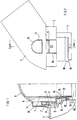
- eine Anordnung zum lösbaren Verbinden eines Saugstutzens mit der Saugöffnung eines Staubsaugers im Halbschnitt,
- FIG 2
- eine Seitenansicht eines Saugstutzens.
- Mit 1 ist ein Wandteil eines andeutungsweise dargestellten Staubsaugergehäuses bezeichnet. An dem Wandteil 1 ist die Saugöffnung des Staubsaugers vorgesehen. An diese Saugöffnung 2 ist ein mit einem Saugschlauch verbundener Saugstutzen 3 ankoppelbar. Die Saugöffnung 2 bildet somit einen mit dem Saugstutzen 3 koppelbaren anderen Rohrstutzen. Der eine Saugstutzen 3 weist ein in die Saugöffnung 2 einsteckbares rohrförmiges Ende 4 auf, das auf eine bestimmte axiale Länge von einem Rohransatz 5 des Saugstutzens 3 mit radialem Abstand umgeben ist. Auf diese Weise ergibt sich zwischen dem rohrförmigen Ende 4 und dem Rohransatz 5 ein Ringraum 6.
- In dem Ringraum 6 ist ein Verriegelungselement 7 eingesetzt. Das Verriegelungselement 7 weist einen zu dem rohrförmigen Ende 4 konzentrischen Ringteil 8 auf. An dem Ringteil 8 sind zwei nach radial außen vorstehende Rastnocken 9 angeformt, die jeweils durch eine Schlitz 10 des Rohransatzes 5 hindurch ragen und einen am Wandteil 1 angeformtem Rastvorsprung 11 untergreifen. Hierdurch wird der Saugstutzen 3 am Staubsaugergehäuse in der Saugöffnung 2 gehalten. Axial oberhalb jeder Rastnocke 9 ist jeweils eine durch eine entsprechende Öffnung 12 in der Wand des Saugstutzens 3 nach außen ragende Entriegelungstaste 13 an dem Ringteil 8 vorgesehen. Zum Entkoppeln des Saugstutzens 3 von der Saugöffnung 2 wird auf die Entriegelungstasten 13 ein entsprechender Druck ausgeübt. Hierdurch wird der Ringteil 8 entsprechend nach radial innen verformt, so daß die Rastnasen 9 außer Eingriff mit dem Rastvorsprung 11 kommen und der Saugstutzen 3 aus der Saugöffnung 2 herausgezogen werden kann.
- An dem Verriegelungselement 7 ist ferner eine rohrförmige Verlängerung 14 vorgesehen. Der Innendurchmesser dieser Verlängerung 14 entspricht dem Außendurchmesser des rohrförmigen Endes 4 des Saugstutzens 3, so daß das Verriegelungselement 7 mit seiner Verlängerung 14 auf das rohrförmige Ende 4 des Saugstutzens 3 aufschiebbar ist. An der Innenwand der Verlängerung 14 sind Rastnasen 15 vorgesehen, die in entsprechend angepaßte Rastvertiefungen 16 des rohrförmigen Endes 4 eingreifen. Die Rastnasen 15 und die Rastvertiefungen 16 sind so geformt, daß in Aufschieberichtung des Verriegelungselementes 7 eine Verrastung erfolgt, die in der zu der Aufschieberichtung entgegengesetzten Richtung nicht mehr lösbar ist. Durch die durch die Öffnung 12 ragenden Entriegelungstasten 13 wird die Aufschiebestrecke des Verriegelungselementes 7 derart begrenzt, daß die Rastnasen 15 in Anlage an der Rastkante 17 der Rastvertiefung 16 verbleiben.
- An dem freien Ende der Verlängerung 14 ist als Dichtungselement ein schräg nach radial außen weisender Kragen 18 angeformt, der wiederum an seinem freien Ende mit einer Dichtlippe 19 versehen ist. Der Außendurchmesser der Dichtlippe 19 ist im nicht in die Saugöffnung 2 eingesteckten Zustand des Saugstutzens 3 geringfügig größer bemessen als der Innendurchmesser der Saugöffnung 2 in dem Bereich, in dem sich die Dichtlippe 19 im an die Saugöffnung 2 angekoppelten Zustand des Saugstutzens 3 befindet. Somit wird sicher gestellt, daß sich die Dichtlippe 19 beim Ankoppeln des Saugstutzens 3 an die Saugöffnung 2 unter einem gewissen Spannungszustand an die Wand 20 der Saugöffnung 2 anlegt. Damit ist eine einwandfreie Abdichtung der Koppelstelle des Saugstutzens 3 an die Saugöffnung 2 gewährleistet. Die Güte der Abdichtstelle hängt nicht mehr von irgendwelchen Längentoleranzen der ineinandergefügten Teile ab. Auch haben auf den Saugstutzen 3 ausgeübte Zugkräfte keinen Einfluß mehr auf die Dichtwirkung. Derartige Einflüsse können lediglich zu einer axialen Verschiebung der Berührungslinie der Dichtlippe 19 mit der Wand 20 der Saugöffnung 2 führen.
Claims (4)
- Anordnung zum lösbaren Verbinden eines Saugstutzens mit der Saugöffnung eines Staubsaugers, bei welcher Anordnung zumindest an dem Saugstutzen (3) dessen koppelbares, rohrförmiges Ende (4) auf eine bestimmte axiale Länge von einem radial beabstandeten Rohransatz (5) umgeben ist, wobei in dem zwischen dem rohrförmigen Ende (4) und dem Rohransatz (5) gebildeten Ringraum (6) ein mindestens eine Entriegelungstaste (13) und mindestens ein durch Federkraft in einer in der Saugöffnnung (2) vorgesehenen Gegenrast (11) gehaltenes Rastglied (9) aufweisendes Verriegelungselement (7) angeordnet ist, durch das der Saugtutzen (3) lösbar mit der Saugöffnung (2) gekoppelt ist,
dadurch gekennzeichnet,
daß an dem Verriegelungselement (7) eine auf das rohrförmige Ende (4) aufsteckbare rohrförmige Verlängerung (14) vorgesehen ist, an deren freiem Ende ein den zwischen dem rohrförmigen Ende (4) und der Saugöffnung (2) bestehenden Ringspalt abdichtendes Dichtelement (18) angeordnet ist. - Anordnung nach Anspruch 1,
dadurch gekennzeichnet,
daß an dem freien Ende der Verlängerung (14) eine elastische Dichtlippe (18) angeformt ist. - Anordnung nach Anspruch 2,
dadurch gekennzeichnet,
daß als Dichtlippe an dem rohrförmigen Teil der Verlängerung (14) ein schräg nach außen weisender Kragen (18) angeformt ist. - Anordnung nach einem der vorhergehenden Ansprüche,
dadurch gekennzeichnet,
daß das Verriegelungselement (7) an der Innenseite seiner rohrförmigen Verlängerung (14) ein an dem rohrförmigen Ende (4) des Saugstutzens (3) verrastbares Rastelement (15) aufweist.
Applications Claiming Priority (2)
| Application Number | Priority Date | Filing Date | Title |
|---|---|---|---|
| DE19616389A DE19616389A1 (de) | 1996-04-24 | 1996-04-24 | Anordnung zum lösbaren Verbinden eines Saugstutzens mit der Saugöffnung eines Staubsaugers |
| DE19616389 | 1996-04-24 |
Publications (3)
| Publication Number | Publication Date |
|---|---|
| EP0803225A2 true EP0803225A2 (de) | 1997-10-29 |
| EP0803225A3 EP0803225A3 (de) | 1998-04-29 |
| EP0803225B1 EP0803225B1 (de) | 2001-11-14 |
Family
ID=7792322
Family Applications (1)
| Application Number | Title | Priority Date | Filing Date |
|---|---|---|---|
| EP97105992A Expired - Lifetime EP0803225B1 (de) | 1996-04-24 | 1997-04-10 | Anordnung zum lösbaren Verbinden eines Saugstutzens mit der Saugöffnung eines Staubsaugers |
Country Status (3)
| Country | Link |
|---|---|
| EP (1) | EP0803225B1 (de) |
| DE (2) | DE19616389A1 (de) |
| ES (1) | ES2168536T3 (de) |
Cited By (6)
| Publication number | Priority date | Publication date | Assignee | Title |
|---|---|---|---|---|
| EP1356756A1 (de) * | 2002-04-26 | 2003-10-29 | Truplast Kunststofftechnik Gmbh | Kupplungsmuffe für die Verbindung eines Saugschlauchs mit einem Gehäuse |
| FR2918259A1 (fr) * | 2007-07-03 | 2009-01-09 | Seb Sa | Connexion etanche pour aspirateur |
| DE112007002189T5 (de) | 2006-11-13 | 2009-09-24 | Kolektor Liv Predelava Plastike D.O.O. | Schlauchkupplung für einen Staubsauger |
| WO2011012482A1 (de) | 2009-07-31 | 2011-02-03 | BSH Bosch und Siemens Hausgeräte GmbH | Staubsauger mit stutzen |
| EP2385282A1 (de) * | 2010-05-07 | 2011-11-09 | Otto Bock Healthcare GmbH | Ventilanordnung mit einem Basisteil und einem Einsatzteil |
| WO2015159046A1 (en) * | 2014-04-16 | 2015-10-22 | Dyson Technology Limited | Cleaning implement for a vacuum cleaner and cleaning apparatus |
Families Citing this family (4)
| Publication number | Priority date | Publication date | Assignee | Title |
|---|---|---|---|---|
| DE102010039282A1 (de) | 2010-08-12 | 2012-02-16 | BSH Bosch und Siemens Hausgeräte GmbH | Anschlussstutzen mit Rastelement |
| DE102010039285B3 (de) | 2010-08-12 | 2012-01-26 | BSH Bosch und Siemens Hausgeräte GmbH | Anschlussstutzen für einen Staubsauger |
| DE102010039283A1 (de) | 2010-08-12 | 2012-02-16 | BSH Bosch und Siemens Hausgeräte GmbH | Anschlussstutzen mit Federelement |
| DE102010039286A1 (de) | 2010-08-12 | 2012-02-16 | BSH Bosch und Siemens Hausgeräte GmbH | Anschlussstutzen für einen Staubsauger mit Rastelement |
Family Cites Families (6)
| Publication number | Priority date | Publication date | Assignee | Title |
|---|---|---|---|---|
| US2367188A (en) * | 1943-04-27 | 1945-01-16 | Landers Frary & Clark | Hose coupling for vacuum cleaners |
| DE2132181A1 (de) * | 1971-06-29 | 1973-01-11 | Siemens Elektrogeraete Gmbh | Rohrverbindung, insbesondere von staubsaugerrohren |
| DE3214682C2 (de) * | 1982-04-21 | 1987-01-29 | Progress-Elektrogeräte Mauz & Pfeiffer GmbH & Co, 7000 Stuttgart | Reinigungsgerät für Staubsauger |
| DE3312193A1 (de) * | 1983-04-02 | 1984-10-04 | Licentia Patent-Verwaltungs-Gmbh, 6000 Frankfurt | Kupplung fuer einen saugschlauch |
| DE8522551U1 (de) * | 1985-08-05 | 1986-12-04 | Siemens AG, 1000 Berlin und 8000 München | Anordnung zum lösbaren Verbinden des Anschlußstutzens eines Saugschlauches in einer am Staubsaugergehäuse vorgesehenen Saugöffnung |
| SE460331B (sv) * | 1988-02-09 | 1989-10-02 | Electrolux Ab | Kopplingsanordning |
-
1996
- 1996-04-24 DE DE19616389A patent/DE19616389A1/de not_active Withdrawn
-
1997
- 1997-04-10 EP EP97105992A patent/EP0803225B1/de not_active Expired - Lifetime
- 1997-04-10 DE DE59705327T patent/DE59705327D1/de not_active Expired - Lifetime
- 1997-04-10 ES ES97105992T patent/ES2168536T3/es not_active Expired - Lifetime
Cited By (9)
| Publication number | Priority date | Publication date | Assignee | Title |
|---|---|---|---|---|
| EP1356756A1 (de) * | 2002-04-26 | 2003-10-29 | Truplast Kunststofftechnik Gmbh | Kupplungsmuffe für die Verbindung eines Saugschlauchs mit einem Gehäuse |
| DE112007002189T5 (de) | 2006-11-13 | 2009-09-24 | Kolektor Liv Predelava Plastike D.O.O. | Schlauchkupplung für einen Staubsauger |
| FR2918259A1 (fr) * | 2007-07-03 | 2009-01-09 | Seb Sa | Connexion etanche pour aspirateur |
| WO2011012482A1 (de) | 2009-07-31 | 2011-02-03 | BSH Bosch und Siemens Hausgeräte GmbH | Staubsauger mit stutzen |
| DE102009035604A1 (de) | 2009-07-31 | 2011-02-10 | BSH Bosch und Siemens Hausgeräte GmbH | Staubsauger mit Stutzen |
| EP2385282A1 (de) * | 2010-05-07 | 2011-11-09 | Otto Bock Healthcare GmbH | Ventilanordnung mit einem Basisteil und einem Einsatzteil |
| DE102010020068A1 (de) * | 2010-05-07 | 2011-11-10 | Otto Bock Healthcare Gmbh | Ventilanordnung mit einem Basisteil und einem Einsatzteil |
| WO2015159046A1 (en) * | 2014-04-16 | 2015-10-22 | Dyson Technology Limited | Cleaning implement for a vacuum cleaner and cleaning apparatus |
| CN105011858A (zh) * | 2014-04-16 | 2015-11-04 | 戴森技术有限公司 | 用于真空吸尘器的清洁工具和清洁装置 |
Also Published As
| Publication number | Publication date |
|---|---|
| ES2168536T3 (es) | 2002-06-16 |
| EP0803225A3 (de) | 1998-04-29 |
| DE19616389A1 (de) | 1997-10-30 |
| EP0803225B1 (de) | 2001-11-14 |
| DE59705327D1 (de) | 2001-12-20 |
Similar Documents
| Publication | Publication Date | Title |
|---|---|---|
| DE3873033T2 (de) | Bewegliche verbindung fuer rohrfoermige leitungen. | |
| DE3813192C2 (de) | ||
| EP0379655B1 (de) | Verbindungsvorrichtung | |
| DE4030277C2 (de) | Verbinder für Rohre geringen Durchmessers | |
| DE4001275A1 (de) | Zwischen einer metallrohrleitung geringen durchmessers und einem flexiblen schlauch eingebrachter konnektor | |
| EP0806597A1 (de) | Schnellkupplung | |
| EP0465896A1 (de) | Verbindungselement für Wellrohre und Schläuche | |
| EP1361385A1 (de) | Rohrpressverbindung | |
| DE19715899A1 (de) | Steckkupplung mit Auslaufschutz | |
| EP0510369B1 (de) | Kupplungseinrichtung für ein Schlauchsystem | |
| EP0579194B1 (de) | Steckarmatur zum schnellen und lösbaren Anschluss von Rohrleitungen | |
| EP0474657B1 (de) | Schlauchsteckkupplung | |
| DE69612171T2 (de) | Steckkupplung mit Federverrieglung | |
| EP0247214B1 (de) | Steckarmatur zum lösbaren Anschluss einer Kunststoffleitung mit abgedichtetem Spannelement | |
| EP0803225A2 (de) | Anordnung zum lösbaren Verbinden eines Saugstutzens mit der Saugöffnung eines Staubsaugers | |
| DE69829545T2 (de) | Kupplung mit vergrößerter Rückhaltevorrichtung | |
| EP1636521B1 (de) | Verbindungseinrichtung für ein rohr oder dgl | |
| DE29921406U1 (de) | Steckarmatur zum schnellen und lösbaren Anschluß von Druckmittel-Leitungen | |
| EP1264127B1 (de) | Drehbarer absperrhahn für eine steckkupplung mit abgewinkeltem anschlussstutzen | |
| DE2822259C2 (de) | Schnellkupplung für rohrförmige Leitungen, insbesondere für Flüssigkeiten | |
| EP0003746B1 (de) | Steckarmatur | |
| EP2438842A2 (de) | Anschlussstutzen mit Rastelement | |
| EP0545037A1 (de) | Vorrichtung zum gegenseitigen Verbinden von zwei Leitungen, insbesondere Kraftstoffleitungen | |
| DE4205142C1 (de) | ||
| DE3529052C2 (de) | Schlauchsteckverbindung |
Legal Events
| Date | Code | Title | Description |
|---|---|---|---|
| PUAI | Public reference made under article 153(3) epc to a published international application that has entered the european phase |
Free format text: ORIGINAL CODE: 0009012 |
|
| AK | Designated contracting states |
Kind code of ref document: A2 Designated state(s): DE ES FR GB IT SE |
|
| PUAL | Search report despatched |
Free format text: ORIGINAL CODE: 0009013 |
|
| AK | Designated contracting states |
Kind code of ref document: A3 Designated state(s): DE ES FR GB IT SE |
|
| 17P | Request for examination filed |
Effective date: 19981012 |
|
| GRAG | Despatch of communication of intention to grant |
Free format text: ORIGINAL CODE: EPIDOS AGRA |
|
| GRAG | Despatch of communication of intention to grant |
Free format text: ORIGINAL CODE: EPIDOS AGRA |
|
| GRAH | Despatch of communication of intention to grant a patent |
Free format text: ORIGINAL CODE: EPIDOS IGRA |
|
| 17Q | First examination report despatched |
Effective date: 20010406 |
|
| RAP1 | Party data changed (applicant data changed or rights of an application transferred) |
Owner name: BSH BOSCH UND SIEMENS HAUSGERAETE GMBH |
|
| GRAH | Despatch of communication of intention to grant a patent |
Free format text: ORIGINAL CODE: EPIDOS IGRA |
|
| GRAA | (expected) grant |
Free format text: ORIGINAL CODE: 0009210 |
|
| AK | Designated contracting states |
Kind code of ref document: B1 Designated state(s): DE ES FR GB IT SE |
|
| GBT | Gb: translation of ep patent filed (gb section 77(6)(a)/1977) |
Effective date: 20011114 |
|
| REF | Corresponds to: |
Ref document number: 59705327 Country of ref document: DE Date of ref document: 20011220 |
|
| REG | Reference to a national code |
Ref country code: GB Ref legal event code: IF02 |
|
| ET | Fr: translation filed | ||
| PG25 | Lapsed in a contracting state [announced via postgrant information from national office to epo] |
Ref country code: SE Free format text: LAPSE BECAUSE OF FAILURE TO SUBMIT A TRANSLATION OF THE DESCRIPTION OR TO PAY THE FEE WITHIN THE PRESCRIBED TIME-LIMIT Effective date: 20020214 |
|
| REG | Reference to a national code |
Ref country code: ES Ref legal event code: FG2A Ref document number: 2168536 Country of ref document: ES Kind code of ref document: T3 |
|
| PLBE | No opposition filed within time limit |
Free format text: ORIGINAL CODE: 0009261 |
|
| STAA | Information on the status of an ep patent application or granted ep patent |
Free format text: STATUS: NO OPPOSITION FILED WITHIN TIME LIMIT |
|
| 26N | No opposition filed | ||
| PGFP | Annual fee paid to national office [announced via postgrant information from national office to epo] |
Ref country code: GB Payment date: 20120423 Year of fee payment: 16 Ref country code: FR Payment date: 20120511 Year of fee payment: 16 |
|
| PGFP | Annual fee paid to national office [announced via postgrant information from national office to epo] |
Ref country code: IT Payment date: 20120424 Year of fee payment: 16 |
|
| PGFP | Annual fee paid to national office [announced via postgrant information from national office to epo] |
Ref country code: ES Payment date: 20120423 Year of fee payment: 16 |
|
| GBPC | Gb: european patent ceased through non-payment of renewal fee |
Effective date: 20130410 |
|
| PG25 | Lapsed in a contracting state [announced via postgrant information from national office to epo] |
Ref country code: GB Free format text: LAPSE BECAUSE OF NON-PAYMENT OF DUE FEES Effective date: 20130410 |
|
| REG | Reference to a national code |
Ref country code: FR Ref legal event code: ST Effective date: 20131231 |
|
| PG25 | Lapsed in a contracting state [announced via postgrant information from national office to epo] |
Ref country code: FR Free format text: LAPSE BECAUSE OF NON-PAYMENT OF DUE FEES Effective date: 20130430 Ref country code: IT Free format text: LAPSE BECAUSE OF NON-PAYMENT OF DUE FEES Effective date: 20130410 |
|
| REG | Reference to a national code |
Ref country code: ES Ref legal event code: FD2A Effective date: 20140606 |
|
| PG25 | Lapsed in a contracting state [announced via postgrant information from national office to epo] |
Ref country code: ES Free format text: LAPSE BECAUSE OF NON-PAYMENT OF DUE FEES Effective date: 20130411 |
|
| REG | Reference to a national code |
Ref country code: DE Ref legal event code: R081 Ref document number: 59705327 Country of ref document: DE Owner name: BSH HAUSGERAETE GMBH, DE Free format text: FORMER OWNER: BSH BOSCH UND SIEMENS HAUSGERAETE GMBH, 81739 MUENCHEN, DE Effective date: 20150402 |
|
| PGFP | Annual fee paid to national office [announced via postgrant information from national office to epo] |
Ref country code: DE Payment date: 20160430 Year of fee payment: 20 |
|
| REG | Reference to a national code |
Ref country code: DE Ref legal event code: R071 Ref document number: 59705327 Country of ref document: DE |