EP0802262A1 - Verfahren zum frischen in einem konverter von oben mit hervorragenden enthohlungseigenschaften und blaslanze zum frischen von oben - Google Patents
Verfahren zum frischen in einem konverter von oben mit hervorragenden enthohlungseigenschaften und blaslanze zum frischen von oben Download PDFInfo
- Publication number
- EP0802262A1 EP0802262A1 EP96900181A EP96900181A EP0802262A1 EP 0802262 A1 EP0802262 A1 EP 0802262A1 EP 96900181 A EP96900181 A EP 96900181A EP 96900181 A EP96900181 A EP 96900181A EP 0802262 A1 EP0802262 A1 EP 0802262A1
- Authority
- EP
- European Patent Office
- Prior art keywords
- lance
- nozzle
- oxygen
- gas
- range
- Prior art date
- Legal status (The legal status is an assumption and is not a legal conclusion. Google has not performed a legal analysis and makes no representation as to the accuracy of the status listed.)
- Granted
Links
Images






Classifications
-
- C—CHEMISTRY; METALLURGY
- C21—METALLURGY OF IRON
- C21C—PROCESSING OF PIG-IRON, e.g. REFINING, MANUFACTURE OF WROUGHT-IRON OR STEEL; TREATMENT IN MOLTEN STATE OF FERROUS ALLOYS
- C21C5/00—Manufacture of carbon-steel, e.g. plain mild steel, medium carbon steel or cast steel or stainless steel
- C21C5/28—Manufacture of steel in the converter
- C21C5/30—Regulating or controlling the blowing
- C21C5/32—Blowing from above
-
- C—CHEMISTRY; METALLURGY
- C21—METALLURGY OF IRON
- C21C—PROCESSING OF PIG-IRON, e.g. REFINING, MANUFACTURE OF WROUGHT-IRON OR STEEL; TREATMENT IN MOLTEN STATE OF FERROUS ALLOYS
- C21C5/00—Manufacture of carbon-steel, e.g. plain mild steel, medium carbon steel or cast steel or stainless steel
- C21C5/28—Manufacture of steel in the converter
- C21C5/42—Constructional features of converters
- C21C5/46—Details or accessories
- C21C5/4606—Lances or injectors
Definitions
- the present invention relates to a refining method featuring excellent decarburization in a top- and bottom-blown converter and to a top-blown lance for the converter.
- the refining reaction in a top-blown converter and in a top- and bottom-blown converter proceeds by supplying an oxygen gas from a top-blown lance to oxidize impurities such as carbon, silicon, phosphorus, etc.
- the top-blown lance usually employs a convergent-divergent nozzle having a single aperture or a plurality of apertures in order to efficiently convert the secondary pressure of the lance into kinetic energy of a jet of oxygen gas, and as a result, the stirring in a steel bath is promoted by the jet.
- the top-blown lance as described above is used and the refining is carried out under a secondary pressure within a proper range of expansion of the convergent-divergent nozzle from the first period of refining up to the last period of refining, however, an optimum flow rate or a velocity of jet of oxygen gas depending upon the refining steps cannot be selected freely.
- the rate determining step of supplying oxygen in the initial period of refining therefore, when the flow rate of oxygen gas is increased to increase the rate of decarburization, the velocity of jet of oxygen gas is increased, as a result, the amount of dust and spitting increases.
- the velocity of jet becomes so small that the temperature at a hot spot where jet impinges on the steel bath drops or the stirring force becomes insufficient, resulting in a decrease in the rate of decarburization.
- the decarburization in the converter i.e., 1 in a high carbon range, dust is generated less and the slag is formed quickly, 2 in an intermediate carbon range, the decarburization oxygen efficiency is high, and 3 the decarburization proceeds up to a low carbon range while suppressing the formation of iron oxide.
- the converter dust of 1 is generated from two sources, i.e., the dust is generated from a surface (hot spot) where the top-blown oxygen impinges the steel bath, namely, is generated by vaporization of iron from the high-temperature hot spot or is generated by volumetric expansion of a molten steel which occurs when the CO gas is formed by the decarburization reaction at the hot spot.
- Japanese Unexamined Patent Publication (Kokai) No. 2-156012 discloses a method by which the height of the lance is increased and an inert gas is mixed into the top-blown gas in order to decrease the amount of dust formation. According to this method, the post combustion rate increases accompanying an increase in the height of the lance, and the heat transfer efficiency decreases. Therefore, melt loss increases considerably in the converter refractories. Besides, inert gas is used in large amounts, which is disadvantageous.
- the generating rate of dust is dependent upon a value that is obtained by dividing the oxygen supplying rate by the area of hot spot.
- the productivity decreases.
- a nozzle having many apertures is used to increase the area of hot spot, on the other hand, the hot spots are overlapped one upon the other causing the splash to increase.
- the height of the lance is increased, furthermore, the post combustion rate increases causing the heat transfer efficiency to decrease. Therefore, melt loss occurs conspicuously in the converter refractories.
- Japanese Unexamined Patent Publication (Kokai) No. 62-228424 discloses technology for increasing the post combustion rate by using a top-blown lance nozzle that is greatly deformed like that of a star type. Though there has been described no effect of this technology for decreasing dust or splash, simple use of this lance does not help decrease the dust.
- the velocity of jet of the oxygen gas arriving at the bath surface can be decreased, i.e., the jet velocity (u) can be lowered or, in other words, a soft blow is accomplished.
- the jet velocity (u) can be lowered or, in other words, a soft blow is accomplished.
- u the jet velocity
- the temperature drops in the region (hot spot) where the jet of oxygen gas impinges the bath surface. Therefore, the decarburization oxygen efficiency starts decreasing from a range of a high carbon concentration, and the above-mentioned object 2 is not fulfilled.
- Japanese Unexamined Patent Publications (Kokai) Nos. 60-131908 and 60-63307 disclose technology for mixing a top-blown oxygen gas and an inert gas as represented by argon together in the ultra-low carbon range. These methods, however, require argon gas in large amounts, resulting in a great increase in the cost of gas.
- Japanese Examined Patent Publication (Kokoku) No. 47-4770 discloses a lance provided with a spindle having an operation mechanism that moves up and down in a tubular passage between the opening at an end of a circular oxygen nozzle of the top-blown lance and a throat portion (narrowest portion of the lance nozzle).
- oxygen flows through slit portions formed in gaps between the circular nozzle and the spindle, but the jets passing through the gaps meet together immediately after the opening to establish a hard blow. Even when the gaps are broadened, therefore, a soft blow is not realized.
- Japanese Unexamined Patent Publication (Kokai) No. 1-123016 discloses a lance having a nozzle for inert gas such as Ar or CO 2 in addition to a nozzle for supplying oxygen.
- a nozzle for inert gas such as Ar or CO 2
- the velocity of the jet does not decrease due to the inert gas.
- the oxygen gas is supplied from only one kind of nozzle, the skull is formed on the nozzle to clog it when the flow rate of the oxygen gas is greatly lowered. It is not, therefore, possible to greatly change the flow rate of the oxygen gas or the velocity of jet.
- Japanese Unexamined Patent Publication (Kokai) No. 1-219116 discloses a lance having a main hole and a sub-hole which is coupled to an oxygen-supplying pipe which is independent from the main hole. Due to the problem of clogging of the nozzle caused by forming the skull, however, it is not allowed to greatly decrease the flow rate of the oxygen gas. Besides, since the oxygen gas is supplied through both the main hole and the sub-hole, it is not possible to greatly change the flow rate or the velocity of the jet of oxygen gas.
- the object of the present invention is to solve the above mentioned defects and to provide a method which maintains the velocity of a jet within a nearly predetermined range without affected the flow rate of the oxygen gas by solving the above-mentioned defects, in order to realize the high-speed blowing, to lower dust and spitting, to prevent super oxidizing of the steel bath and to lower the amount of iron oxide in the slag, without employing a complex mechanism.
- Another object of the present invention is to provide a novel nozzle for a top-blown converter which is based on the two new discoveries, i.e., the velocity of flow of a gas blown through a so-called long and narrow shaped jet hole having a large ratio of the short side to the long side and a suitable shape of jet hole, greatly attenuates immediately after it is blown compared with that of the gas blown through a circular hole, as a result, it is possible to realize a soft blow, and by a gas blown through an elongated jet hole and a gas blown through a separate circular nozzle are combined together under suitable conditions, it is possible to realize a hard blow.
- the present invention provides a method of blowing for decarburization as well as a nozzle for blowing as described below.
- the gist of the present invention resides in a refining method in a converter by utilizing an improperly expanding jet wherein, in effecting the blowing for decarburization by using a top-blown lance, the absolute secondary pressure P 0 of a nozzle is maintained within a range of from 0.7 to 2.5 times as great as the properly expanding absolute secondary pressure P 0p of the nozzle of the lance, and the flow rate of the oxygen gas is changed by at least one time changing the absolute secondary pressure during the blowing.
- the absolute secondary pressure P 0 of nozzle is an absolute pressure of a stagnating portion over the throat portion of the nozzle.
- the absolute secondary pressure P 0 of the nozzle is changed at least one time while maintaining a nearly constant distance LG between the end of the nozzle and the static bath surface of the molten steel found according to the above-mentioned formula (1) in an improperly expanding range where an absolute secondary pressure ratio P 0 /P 0p of nozzle is from 0.85 to 1.75, and the oxygen supplying rate is decreased depending upon the amount of the solid-dissolved carbon remaining in the molten steel without changing the velocity of the jet of the oxygen gas and maintaining a predetermined depth of the cavity in the molten steel.
- the molten steel is stirred to a sufficient degree in the last period of decarburization and the formation of iron oxide is suppressed.
- a distance LG between the end of lance and the static bath surface of the molten metal is found in accordance with the formula (1) accompanying a change in the absolute secondary pressure of nozzle P 0 so that a predetermined cavity depth L in the molten steel is maintained within a range of ⁇ 20% of a predetermined value, and the blowing is executed at the above-found height of the lance, i.e., the distance LG.
- the distance LG in the case of the present invention becomes much larger than the distance LG of when the nozzle of which the pressure P 0 is the properly expanding absolute secondary pressure P 0p is used. That is, in the last period of blowing, the blowing can be executed to a sufficient degree without the need of lowering the lance to a low position at which the end of the lance is thermally deformed and is damaged.
- the oxygen supplying rate per a unit weight of the molten steel is set to be from 150 to 300 Nm 3 /h/ton when the carbon concentration is not smaller than 0.5% and is set to be from 20 to 100 Nm 3 /h/ton when the carbon concentration is up to 0.2%.
- the present invention is further characterized by the use of a top-blown lance having gas pipes of two to four independent lines and having a ratio of a minimum line to a maximum line in the total area of the nozzle throat portions of from 2 to 10.
- the present invention provides a lance having gas pipes of two independent lines, i.e., a top-blown lance for a converter having an oxygen-supplying pipe with 2 to 10 shielding portions in the long and narrow shaped nozzle openings of a concentric polygonal shape having 3 to 16 corners or of a concentric circular shape in cross section, and having 1 to 6 circular nozzles formed on the inside of the concentric polygonal or circular long and narrow shaped nozzles independent of the above-mentioned oxygen-supplying pipe.
- the lance of the present invention is constituted by two elements, i.e., forming suitably the long and narrow shaped nozzles that create a soft blow, and a relationship between the long and narrow shaped nozzles and circular nozzles of the inner side for properly accomplishing the merging.
- the distance LG i.e., the height of the end of the lance, can be maintained at a still lower position in the initial period and in the intermediate period of blowing.
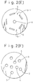
- Fig. 2 illustrates an end portion of the lance, wherein Fig. 2(A) is a plan view of a lance having one line, Fig. 2(B) is a sectional view along the line X-X of Fig. 2(A), Fig. 2(C) is a plan view of a lance having two lines, and Fig. 2(D) is a sectional view along the line Y-Y of Fig. 2(C).
- the lance N 1 of one line has circular nozzles 1-1 formed in the end of a circular gas-supplying pipe 1 so as to be opened as designated at 3 in the end surface of the lance.
- the lance N 2 of two lines has a central circular gas-supplying pipe 2 arranged at the center of the circumferential circular gas-supplying pipe 1, and has nozzles 1-1 and 2-1 that are opened as designated at 3 and 4 in the end surface of the lance.
- Symbol d t denotes a diameter of a nozzle throat portion S
- d e denotes a diameter of the opening 3 or 4.
- the absolute secondary pressure P 0 of the nozzle represents the absolute secondary pressure of a gas in the stagnating portion over the nozzle throat portion, and assumes a value obtained by adding 1.033 kgf/cm 2 (atmospheric pressure) to a value indicated on an ordinary pressure gauge.
- the properly expanding absolute secondary pressure P 0p of nozzle is a value found in accordance with the above-mentioned formula (2) and is a constant value determined by the shape of the lance.
- Symbol P e is a pressure on the outside of the nozzle and is, usually, atmospheric pressure.
- the oxygen gas is supplied to the molten steel by using the above-mentioned nozzles.
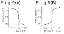
- U max is a maximum jet velocity on a plane perpendicular to the direction of the gas jet
- U maxP is a maximum jet velocity of during the proper expansion (expansion which occurs when P 0 is the same as P 0p determined by the shape of a nozzle from which the gas is released)
- the jet velocity u is a measured value
- the blowing has been carried out under a secondary pressure within a range of proper expansion of the nozzle (e.g., U max /U maxP : 1 when P 0 /P 0p : 1 in Fig. 1) from the initial period to the last period of refining, and it was not possible to freely select an optimum oxygen supplying rate (F 02 ) or the jet velocity (u) that suits the steps of refining.
- a secondary pressure within a range of proper expansion of the nozzle (e.g., U max /U maxP : 1 when P 0 /P 0p : 1 in Fig. 1) from the initial period to the last period of refining, and it was not possible to freely select an optimum oxygen supplying rate (F 02 ) or the jet velocity (u) that suits the steps of refining.
- the oxygen supplying rate can be greatly changed while maintaining a maximum jet velocity within a nearly predetermined range without greatly changing the distance between the end of the lance and the static bath surface of the molten steel. In the initial period of refining, therefore, the oxygen supplying rate can be increased without greatly increasing the velocity of the jet. Even when the blowing is effected at a high speed, therefore, it is allowed to decrease the amount of generation of dust and spitting per the oxygen supplying rate.
- the oxygen supplying rate can be lowered without greatly decreasing the velocity of the jet. Therefore, since a hot spot of a high temperature is easily obtained and the stirring force is maintained, the decarburization can be advantageously carried out.
- a maximum value of the absolute secondary pressure of a nozzle during the blowing is set to be not smaller than 1.1 times as great as its minimum value, so that the oxygen supplying rate can be greatly changed.
- the absolute secondary pressure of a nozzle is maintained to be from 0.85 to 1.75 times of the properly expanding secondary pressure of nozzle, in order to further narrow the range in which the velocity of the jet varies.
- the above-mentioned operation means is entirely to carry out the decarburization by utilizing the improperly expanding jet, that had not been considered so far.
- the cavity depth L in the molten steel is set to a predetermined value (target value), in advance, in proportion to an object of blowing so that L/L 0 (L 0 : depth of steel bath) lies within a range of from 0.3 to 0.7, and the distance LG between the end of the lance and the static bath surface of the molten steel is adjusted relying upon the predetermined value and the value P 0 /P 0p .
- the distance LG is found from the formula (1) by using the upper-limit value of the above value, i.e., by using 1.75, and the absolute secondary pressure P 0 of a nozzle, i.e., the oxygen supplying rate is adjusted by this height of nozzle depending upon the state of decarburization.
- the oxygen supplying rate F 02 blown from a nozzle having a constant sectional area of an opening varies in proportion to the absolute secondary pressure P 0 of a nozzle.
- the allowable range of the depth L from the target value is ⁇ 20%.
- the refining time is greatly lengthened in a range where the carbon concentration is not smaller than 0.5% where the decarburization oxygen efficiency becomes a maximum during the blowing.
- the oxygen supplying rate is set to be larger than 300 Nm 3 /h/ton, on the other hand, dust and spitting are generated in large amounts.
- the stirring force becomes insufficient and the decarburization rate decreases when the oxygen supplying rate is set to be smaller than 20 Nm 3 /h/ton.
- the oxygen supplying rate is set to be larger than 100 Nm 3 /h/ton, on the other hand, the steel bath tends to be excessively oxidized and iron oxide tends to be formed in the slag.
- the above-mentioned method can be put into practice by using a lance having a pipe of one line as shown in Figs. 2(A) and 2(B) but, preferably, using a lance having gas pipes of 2 to 4 independent lines.
- a lance having gas pipes of 2 to 4 independent lines This is because, by using the pipe of one line, the amount of change in the flow rate of oxygen gas is 3.57 times the minimum flow rate at the greatest.
- the flow rate of oxygen gas can be changed by more than 3.57 times.
- the pipes of five or more lines are used, on the other hand, the structure of the lance becomes so complex that the lance is fabricated with difficulty.
- a central circular gas-supplying pipe 2 and a circumferential circular gas-supplying pipe 1 which are constructed of two lines, which are capable of controlling the flow rate independently each other and are coupled to pipes having a flow rate control valve and a flow meter, respectively are provided.
- the central circular gas-supplying pipe 2 is coupled to a central opening 4 through a circular nozzle 2-1
- the circumferential circular gas-supplying pipe 1 is coupled to four circumferential openings 3 through circular nozzles 1-1, the central opening 4 being surrounded by the four circumferential openings 3.
- the oxygen jets through the circumferential openings 3 arrive at the surface of the molten metal in a separate manner like those through an ordinary multi-hole nozzle to create a soft blow.
- the average oxygen supplying rate of oxygen gas per one opening of the central opening 4 is larger than 70% of the average oxygen supplying rate per one opening of the circumferential openings 3 (condition 2), the central jet interferes with the jets through the circumferential openings 3, and the jets arrive at the bath surface in a merged form to create a hard blow that corresponds to that of a single-hole lance.
- the ratio of oxygen supplying rates, through the central opening 4 and through the circumferential openings 3, is so adjusted during the blowing as to at least include the processing that satisfies the condition 1 and the processing that satisfies the condition 2, thereby to obtain, as required, a soft blow of the multi-hole lance and a hard blow corresponding to that of a single-hole lance.
- the conditions 1 and 2 are defined because of the following reasons. That is, the present inventors have learned through study that in the lance of the structure used in the present invention, the critical condition for merging or separating the jets through the circumferential openings and the jet through the central opening involving interference, lies in a range where the average oxygen supplying rate per one opening of the central opening is greater than 50% but is smaller than 70% of the average oxygen supplying rate per one opening of the circumferential openings.
- the critical condition for merging or separating the jets through the circumferential openings and the jet through the central opening involving interference lies in a range where the average oxygen supplying rate per one opening of the central opening is greater than 50% but is smaller than 70% of the average oxygen supplying rate per one opening of the circumferential openings.
- the critical condition for merging or separating the jets through the circumferential openings and the jet through the central opening involving interference lies in a range where the average oxygen supplying rate per one opening of the central opening is greater than 50% but is smaller than 70% of the average oxygen
- the shape of the circumferential openings needs not be limited to a circular shape but may be of a shape of short strips or the like shape as shown in Fig. 2(E).
- the number of the jets arriving at the surface of the molten metal can be changed into a predetermined number by adjusting the positions, spout angle and number of the spout openings which the flow rate is varied.
- the number of the central opening needs not necessarily be one; i.e., the central openings may be arranged in a separate manner (2 to 6 places) surrounded by the circumferential openings 3 as shown in Fig. 2(F).
- This is advantageous for merging the jets together particularly when the angle of aperture ⁇ of the circular nozzle 1-1 is as wide as not smaller than 12 degrees with respect to the perpendicular direction and where the jets are less likely to merge together.
- the condition for merging or separating the jets is evaluated in the same manner as when there is only one opening of the central opening with the ratio of the average oxygen supplying rate per one opening of the circumferential opening to the average oxygen supplying rate per one opening of the central opening as a target.
- the circumferential openings are formed in 2 to 10 places and, preferably, in 3 to 6 places having an angle of aperture ⁇ of 6 to 20 degrees with respect to the perpendicular direction.
- the number of the circumferential openings is specified because of the reason that the soft-blow effect of a multi-hole lance becomes conspicuous when the number of the openings is three or more and that the neighboring jets interfere and merge together irrespective of the flow rate of gas through the central openings when the number of the holes is not smaller than seven.
- the angle of aperture is specified because the jets from the circumferential openings tend to merge together even when the angle of aperture is smaller than 6 degrees irrespective of the gas flow rate through the central opening.
- the jets through the central openings are less likely to be merged.
- the number of the central openings is limited to be not larger than six. This is because it becomes difficult to realize the water-cooling structure when the number of the central holes are increased in order to accelerate merging the jets and, besides, the effect for merging the jets does not increase even if the number of the central holes becomes larger than seven.
- An increased effect for merging is obtained when the angle of aperture of the central openings is not larger than a maximum angle of aperture of the circumferential openings.
- the nozzles having rectangle-like circumferential openings are constituted by an oxygen-supplying pipe having, formed in the end of the top-blown lance, 2 to 10 openings (shielding portions 5-1 are formed in the openings 5 neighboring each other) which are the slit-like nozzles of a concentric polygonal shape having 3 to 16 corners or of a concentric circular shape, and by an oxygen-supplying pipe having 1 to 6 circular nozzle openings 4 on the inside of the slit-like nozzles independently of the above oxygen-supplying pipe.
- the end of the thus constituted lance is formed as a unitary structure by, for example, pouring a metal into a wood frame for forming slit-like nozzles.
- the present invention it is particularly desired to maintain a state where the jets are separated in an intermediate carbon range where the carbon concentration in the molten metal is not smaller than 0.5% by weight and to merge the jets in a low carbon range where the carbon concentration is not larger than 0.2% by weight. That is, when the carbon concentration is not smaller than 0.5% by weight, it is desired that the oxygen supplying rate of the two lines is so adjusted as to satisfy the condition 1 and when the carbon concentration is smaller than 0.2% by weight, it is desired that the oxygen supplying rate of the two lines is so adjusted as to satisfy the condition 2.
- Figs. 7(A) and 7(B) illustrate an example in which long and narrow shaped slit-like nozzles 8 having openings 6 of a concentric circular shape separated by shielding plates 7 are formed at the end of the circumferential gas-supplying pipe 10.
- the lance of this embodiment is constituted by a gas-supplying pipe having 2 to 10 shielding plates arranged in the openings which are slit-like nozzles of a concentric polygonal shape having 3 to 16 corners or of a concentric circular shape in cross section, and by a gas-supplying pipe which is independent from the above pipe and has 1 to 6 circular nozzles on the inside of the slit-like nozzles, the lance body and the end of the lance including the lance center being fastened together via the shielding plates.
- the nozzle has a concentric polygonal or circular slit in cross section, the concentric polygon having 3 to 16 corners This is because a shape with two corners does not exist and, on the other hand, a polygon having more than 16 corners involves difficulty in fabrication.
- the long side (B) becomes very large.
- the long side (B) becomes very small. In either case, therefore, B/h and B ⁇ h do not lie within proper ranges, and the effects of the invention are not obtained.
- the lance body N 2 and the end of the lance including a center point a are secured together via the shielding plates 7, and the center point a does not move up and down relative to the lance body N 2 .
- the lance is constructed in a simple structure, which is a great advantage.
- the jet When the soft blow is continued up to the range where the carbon concentration is smaller than 0.5%, however, much iron is oxidized. In such an intermediate carbon concentration range, therefore, the jet must be intense enough to establish a hard blow.
- the gas must be supplied from the circular nozzles at the center of the lance, and these jets and the jets from the slit-like nozzles must be merged together.
- the average oxygen supplying rate per one opening of the central opening 4 is set to be not smaller than 70% of the average oxygen supplying rate per one opening of the circumferential openings, so as to be interfered by the jets through the circumferential openings 6, so that the merged stream establishes a hard blow that corresponds to the one established by the single-hole lance.
- the circular nozzles are so arranged that an equilateral shape (equilateral triangle in Fig. 7(A)) is formed by connecting the center points of the circular nozzles by straight lines on the lower end surface of the lance, that the geometrical center of gravity of the equilateral shape comes into agreement with the center a of the lance, and that the total length V of partial circumferences V 1 passing through the openings at the end of the circular nozzles, is 0.3 to 0.7 in terms of V/W relative to the circumferential length W of a circle circumscribing the equilateral shape formed by coupling the center points of the circular nozzles by straight lines.
- an equilateral shape equilateral triangle in Fig. 7(A)
- the openings 6 of the slit-like nozzles 8 may be formed in polygonal shapes as shown in Figs. 10(A) to 10(C).
- the blowing is effected in the converter in a state having such a suitable shape, a metallurgical effect that the dust and splash are greatly decreased, as described above, is obtained.
- the soft blowing is established in a state where the height of lance is greatly lowered compared to that of the ordinary circular multi-hole nozzle. Therefore, the post combustion rate does not so increase as to cause the refractories to be damaged. Besides, good heat transfer is obtained since the post combustion takes place in a state where the height of the lance is low.
- the distance LG between the end of the lance and the static bath surface of the molten steel may be found in compliance with the following formula (6) instead of the above-mentioned formula (1) in order to more reliably adjust the cavity depth L in the molten steel during the blowing.
- inert gases such as argon, CO, CO 2 may be blown, as required, together with the oxygen gas through the central nozzles or the circumferential nozzles. This makes it possible to prevent an accident such as clogging of the nozzle openings due to blowing out of the oxygen gas.
- the inert gas is supplied from the circumferential gas-supplying pipe in the last period of blowing.
- oxygen is supplied through the slit-like or circular nozzle coupled to the circumferential gas-supplying pipe and is supplied through the circular nozzle coupled to the central gas-supplying pipe such that L/L 0 is from 0.5 to 0.3, and the oxygen supplying rate per one opening of the circular nozzle coupled to the central gas-supplying pipe is selected to be not larger than 50% of the oxygen supplying rate per one opening of the slit-like or circular nozzle coupled to the circumferential gas-supplying pipe, so that the total oxygen supplying rate through the two supplying pipes is within a range of from 150 to 300 Nm 3 /h/ton.
- oxygen is supplied through the slit-like or circular nozzle coupled to the circumferential gas-supplying pipe and is supplied through the circular nozzle coupled to the central gas-supplying pipe such that L/L 0 is from 0.5 to 0.7, and the oxygen supplying rate per one opening of the circular nozzle coupled to the central gas-supplying pipe is selected to be not smaller than 70% of the oxygen supplying rate per one opening of the slit-like or circular nozzle coupled to the circumferential gas-supplying pipe, so that the total oxygen supplying rate from the two supplying pipes is within a range of from 100 to 200 Nm 3 /h/ton.
- one or two or more kinds of nitrogen, carbon dioxide, argon and carbon monoxide are supplied through the slit-like or circular nozzles coupled to the circumferential gas-supplying pipe in amounts of from 15 to 30 Nm 3 /h/ton and, at the same time, oxygen is supplied through the circular nozzles coupled to the central gas-supplying pipe in an amount of from 20 to 100 Nm 3 /h/ton.
- the absolute secondary pressure of nozzle P 0 /P 0p is set to be from 1.75 to 2.5, in the range where the carbon concentration is from 0.05 to 0.1%, P 0 /P 0p is set to be from 1 to 1.75 and in the range where the carbon concentration is from 0.05 to 0.01%, P 0 /P 0p is set to be from 1 to 0.7.
- Decarburization testing was conducted on nine conditions A, B, C, D, E, F, G, H and I by using a top- and bottom-blown converter having an inner diameter of about 2.1 m and by introducing 6 tons of molten pig-iron.
- the depth L 0 , of the steel bath was about 240 mm. From the testing previously conducted by using this converter, the cavity depth L in the molten steel was presumed to be about 120 mm.
- nitrogen was used as a bottom-blow gas at a rate of 100 Nm 3 /h.
- lime was thrown in an amount of 130 kg so that the basicity (weight ratio of SiO 2 and CaO) of the slag was about 3.5.
- Design values of the nozzles on each of the conditions are shown in Table 1, and the ends of the lances are schematically diagramed in Figs. 2(A) to 2(D).
- the oxygen supplying rate was changed from 167 Nm 3 /h/ton to 67 Nm 3 /h/ton depending upon the carbon concentration, and the ratio P 0 /P 0p of the properly expanding absolute secondary pressure to the absolute secondary pressure of the nozzle was changed from 2.86 to 1.14 correspondingly.
- a maximum ratio P 0 /P 0p on this condition was greater than the upper limit of the range of P 0 /P 0p of the present invention.
- the cavity depth in the molten steel has changed from 240 mm to 55 mm depending upon a change in the oxygen supplying rate.
- the oxygen supplying rate was changed from 167 Nm 3 /h/ton to 67 Nm 3 /h/ton depending upon the carbon concentration, and the ratio P 0 /P 0p of the properly expanding absolute secondary pressure to the absolute secondary pressure of the nozzle was changed from 1.25 to 0.50 correspondingly.
- a minimum ratio P 0 /P 0p on this condition was smaller than the lower limit of the range of P 0 /P 0p of the present invention.
- the cavity depth in the molten steel has changed from 140 mm to 10 mm depending upon a change in the oxygen supplying rate.
- the oxygen supplying rate was changed from 167 Nm 3 /h/ton to 83 Nm 3 /h/ton depending upon the carbon concentration, and the ratio P 0 /P 0p of the properly expanding absolute secondary pressure to the absolute secondary pressure of the nozzle was changed from 1.25 to 0.625 correspondingly.
- a minimum ratio P 0 /P 0p on this condition was smaller than the lower limit of the range of P 0 /P 0p of the present invention.
- the distance between the end of the lance and the static bath surfaces of the molten steel was changed from 900 to 200 mm depending upon the change in the oxygen supplying rate, so that the cavity depth in the molten steel was within ⁇ 20% of the predetermined value of 120 mm.
- the oxygen supplying rate was changed from 167 Nm 3 /h/ton to 67 Nm 3 /h/ton depending upon the carbon concentration, and the ratio P 0 /P 0p of the properly expanding absolute secondary pressure to the absolute secondary pressure of the nozzle was changed from 2.00 to 0.80 correspondingly.
- the ratio P 0 /P 0p on this condition was within the range of P 0 /P 0p of the present invention.
- the cavity depth in the molten steel has changed from 160 mm to 50 mm depending upon a change in the oxygen supplying rate.
- the oxygen supplying rate was changed from 167 Nm 3 /h/ton to 67 Nm 3 /h/ton depending upon the carbon concentration, and the ratio P 0 /P 0p of the properly expanding absolute secondary pressure to the absolute secondary pressure of the nozzle was changed from 2.00 to 0.80 correspondingly.
- the ratio P 0 /P 0p on this condition was within the range of P 0 /P 0p of the present invention.
- the distance between the end of the lance and the static bath surface of the molten steel was changed from 997 mm to 454 mm depending upon a change in the oxygen supplying rate, so that the cavity depth in the molten steel was within ⁇ 20% of the predetermined value of 120 mm.
- the oxygen supplying rate was changed from 145 Nm 3 /h/ton to 72 Nm 3 /h/ton depending upon the carbon concentration, and the ratio P 0 /P 0p of the properly expanding absolute secondary pressure to the absolute secondary pressure of the nozzle was changed from 1.74 to 0.85 correspondingly.
- the ratio P 0 /P 0p on this condition was within the most desirable range of P 0 /P 0p of the present invention.
- the distance between the end of the lance and the static bath surface of the molten steel was set to be 631 mm constant, the cavity depth of the molten steel has changed from 140 mm to 100 mm depending upon a change in the oxygen supplying rate.
- the oxygen supplying rate was changed from 233 Nm 3 /h/ton to 33 Nm 3 /h/ton depending upon the carbon concentration.
- the oxygen supplying rate through the gas pipe of the first line was changed from 233 Nm 3 /h/ton to 83 Nm 3 /h/ton, and the ratio P 0 /P 0p of the properly expanding absolute secondary pressure to the absolute secondary pressure of the nozzle was changed from 2.15 to 0.77 correspondingly.
- the distance between the end of the lance and the static bath surface of the molten steel was changed from 1053 mm to 468 mm depending upon a change in the oxygen supplying rate, and the cavity depth in the molten steel was adjusted to be within ⁇ 20% of the predetermined value of 120 mm.
- the gas pipe was changed over to the gas pipe of the second line, the oxygen supplying rate was changed from 83 Nm 3 /h/ton to 33 Nm 3 /h/ton, and the ratio P 0 /P 0p of the properly expanding absolute secondary pressure to the absolute secondary pressure of the nozzle was changed from 1.92 to 0.77 correspondingly.
- the distance between the end of the lance and the static bath surface of the molten steel was changed from 1363 mm to 624 mm depending upon a change in the oxygen supplying rate, and the cavity depth in the molten steel was adjusted to be within ⁇ 20% of the predetermined value of 120 mm.
- the ratio P 0 /P 0p on this condition was within the range of P 0 /P 0p of the present invention.
- the oxygen supplying rate was changed from 167 Nm 3 /h/ton to 42 Nm 3 /h/ton depending upon the carbon concentration.
- the oxygen supplying rate through the gas pipe of the first line was changed from 167 Nm 3 /h/ton to 83 Nm 3 /h/ton, and the ratio P 0 /P 0p of the properly expanding absolute secondary pressure to the absolute secondary pressure of the nozzle was changed from 1.74 to 0.87 correspondingly.
- the ratio P 0 /P 0p on this condition was within the most desired range of P 0 /P 0p of the present invention.
- the cavity depth in the molten steel has changed from 140 mm to 100 mm depending upon a change in the oxygen supplying rate.
- the gas pipe was changed over to the gas pipe of the second line, the oxygen supplying rate was changed from 83 Nm 3 /h/ton to 42 Nm 3 /h/ton, and the ratio P 0 /P 0p of the properly expanding absolute secondary pressure to the absolute secondary pressure of the nozzle was changed from 1.74 to 0.87 correspondingly.
- the refining was carried out according to the method of the present invention by using the same converter as that of Example 1 and by using a lance that is described below.
- the top-blown lance possessed a basic shape as shown in Figs. 7(A) and 7(B).
- the number of the nozzle openings, shape, gap and the thickness of the shielding plates were changed.
- the distance between the end of the lance and the bath surface was 0.5 to 1.5 m, the concentration of dust during the blowing was measured from the amount of dust in the dust-collecting water and was evaluated as an average rate of generation per unit blowing time.
- the lance was of the type in which the lance body was secured to the end of the lance that includes the center of the lance via the shielding plates.
- the height of the lance was 700 to 900 mm in the period I, 700 to 900 mm in the period II, and 700 mm in the period III.
- the present invention it is possible to maintain the velocity of jets within a nearly predetermined range without being affected by an increase or decrease in the flow rate of the oxygen gas and without so much decreasing the distance between the ends of the nozzles of the blowing lance and the static bath surface of the molten steel. It is therefore allowed to blow at high-speed, to lower the generation of dust and spitting, to prevent the steel bath from being excessively oxidized and to decrease the formation of iron oxide in the slag without increasing the thermal load to the blowing lance. A complex mechanism is not required, either.
Landscapes
- Engineering & Computer Science (AREA)
- Chemical & Material Sciences (AREA)
- Manufacturing & Machinery (AREA)
- Materials Engineering (AREA)
- Metallurgy (AREA)
- Organic Chemistry (AREA)
- Carbon Steel Or Casting Steel Manufacturing (AREA)
Applications Claiming Priority (16)
| Application Number | Priority Date | Filing Date | Title |
|---|---|---|---|
| JP79495A JPH08188816A (ja) | 1995-01-06 | 1995-01-06 | 転炉吹錬方法 |
| JP794/95 | 1995-01-06 | ||
| JP79495 | 1995-01-06 | ||
| JP44602/95 | 1995-03-03 | ||
| JP04460295A JP3655659B2 (ja) | 1995-03-03 | 1995-03-03 | 歩留りの良い転炉上吹き送酸方法 |
| JP4460295 | 1995-03-03 | ||
| JP6734695 | 1995-03-27 | ||
| JP67348/95 | 1995-03-27 | ||
| JP6734695A JPH08157928A (ja) | 1994-10-06 | 1995-03-27 | ダスト発生量が少ない転炉用上吹きランス |
| JP67346/95 | 1995-03-27 | ||
| JP6734895A JPH08165508A (ja) | 1994-10-14 | 1995-03-27 | 脱炭特性に優れた転炉用上吹きランスおよび精錬方法 |
| JP6734895 | 1995-03-27 | ||
| JP8727995 | 1995-04-12 | ||
| JP87279/95 | 1995-04-12 | ||
| JP08727995A JP3655662B2 (ja) | 1995-04-12 | 1995-04-12 | 不適正膨張噴流を利用した溶鉄精錬方法 |
| PCT/JP1996/000008 WO1996021047A1 (en) | 1995-01-06 | 1996-01-05 | Converter top-blow refining method having excellent decarburization characteristics and top-blow lance for converter |
Publications (3)
| Publication Number | Publication Date |
|---|---|
| EP0802262A1 true EP0802262A1 (de) | 1997-10-22 |
| EP0802262A4 EP0802262A4 (de) | 1998-04-22 |
| EP0802262B1 EP0802262B1 (de) | 2003-05-02 |
Family
ID=27517999
Family Applications (1)
| Application Number | Title | Priority Date | Filing Date |
|---|---|---|---|
| EP96900181A Expired - Lifetime EP0802262B1 (de) | 1995-01-06 | 1996-01-05 | Verfahren zum frischen in einem konverter von oben mit hervorragenden enthohlungseigenschaften und blaslanze zum frischen von oben |
Country Status (8)
| Country | Link |
|---|---|
| US (1) | US6017380A (de) |
| EP (1) | EP0802262B1 (de) |
| KR (1) | KR100227066B1 (de) |
| CN (1) | CN1059470C (de) |
| AU (1) | AU693630B2 (de) |
| CA (1) | CA2209647C (de) |
| DE (1) | DE69627819T2 (de) |
| WO (1) | WO1996021047A1 (de) |
Cited By (5)
| Publication number | Priority date | Publication date | Assignee | Title |
|---|---|---|---|---|
| EP1179602A1 (de) * | 2000-08-07 | 2002-02-13 | L'air Liquide, Societe Anonyme Pour L'etude Et L'exploitation Des Procedes Georges Claude | Verfahren zum Einblasen eines Gases mit Hilfe einer Düse |
| FR2816324A1 (fr) * | 2000-11-09 | 2002-05-10 | Air Liquide | Procede d'injection d'un gaz a l'aide d'une tuyere |
| EP1340823A4 (de) * | 2000-11-16 | 2005-03-02 | Jfe Steel Corp | Sauerstoffblasverfahren und aufwärtsblasende lanze für sauerstoffblaskonverter |
| WO2012155225A1 (pt) * | 2011-05-17 | 2012-11-22 | Magnesita Refratários S/A | Lança para injeção de topo em vasos metalúrgicos e método para fabricação dessa lança |
| WO2016166189A1 (en) | 2015-04-16 | 2016-10-20 | Vesuvius Crucible Company | Lance for top injection in metallurgical vessels and process for manufacturing same |
Families Citing this family (9)
| Publication number | Priority date | Publication date | Assignee | Title |
|---|---|---|---|---|
| JP2000073118A (ja) * | 1998-08-26 | 2000-03-07 | Nippon Steel Corp | 簡易取鍋精錬方法 |
| BRPI0918626A2 (pt) * | 2008-09-16 | 2015-12-01 | Istc Co Ltd | processo para produção de ferro fundido |
| JP6721129B2 (ja) * | 2017-08-21 | 2020-07-08 | 日本製鉄株式会社 | 転炉吹錬用上吹きランスおよび溶銑の精錬方法 |
| KR102344147B1 (ko) * | 2017-12-22 | 2021-12-27 | 제이에프이 스틸 가부시키가이샤 | 용철의 송산 정련 방법 및 상취 랜스 |
| EP3954789A4 (de) * | 2019-04-09 | 2022-05-18 | JFE Steel Corporation | Lanzendüse |
| CN114096685A (zh) * | 2019-07-22 | 2022-02-25 | 杰富意钢铁株式会社 | 铁水的脱磷方法 |
| JP7617402B2 (ja) * | 2021-03-17 | 2025-01-20 | 日本製鉄株式会社 | 転炉用上吹きランス及び転炉精錬方法 |
| CN115807146B (zh) * | 2023-01-20 | 2023-07-04 | 北京科技大学 | 一种多介质共用底吹枪的转炉底吹系统及其使用方法 |
| CN116377155B (zh) * | 2023-02-24 | 2024-07-26 | 新疆八一钢铁股份有限公司 | 一种欧冶炉还原竖炉cgd操作控制方法 |
Family Cites Families (15)
| Publication number | Priority date | Publication date | Assignee | Title |
|---|---|---|---|---|
| JPS484690B1 (de) * | 1968-12-16 | 1973-02-10 | ||
| JPS53108814A (en) * | 1977-03-05 | 1978-09-22 | Nippon Steel Corp | Oxygen steel-making method using low phosphorus low sulfur pig iron as raw material |
| JPS5541909A (en) * | 1978-09-14 | 1980-03-25 | Sumitomo Metal Ind Ltd | Blowing method of high carbon material |
| FR2496699B1 (fr) * | 1980-12-22 | 1985-06-21 | Siderurgie Fse Inst Rech | Lance de soufflage de gaz oxydant, notamment d'oxygene, pour le traitement des metaux en fusion |
| JPS609959U (ja) * | 1983-06-29 | 1985-01-23 | 日新製鋼株式会社 | 酸素吹き込みノズル |
| JPS6063307A (ja) * | 1983-09-14 | 1985-04-11 | Kawasaki Steel Corp | 極低炭素鋼の転炉製鋼法 |
| JPS60131908A (ja) * | 1983-12-21 | 1985-07-13 | Kawasaki Steel Corp | 極低炭素鋼の溶製方法 |
| JPS60228424A (ja) * | 1984-04-27 | 1985-11-13 | Hitachi Chem Co Ltd | ビフエニル体の製造法 |
| JPS61143507A (ja) * | 1984-12-17 | 1986-07-01 | Kawasaki Steel Corp | 転炉の2次燃焼促進用ランス |
| JPH01123016A (ja) * | 1987-11-06 | 1989-05-16 | Nkk Corp | 転炉吹錬法 |
| JPH01219116A (ja) * | 1988-02-26 | 1989-09-01 | Sumitomo Metal Ind Ltd | 二次燃焼比率を高めた転炉精錬法 |
| JPH02156012A (ja) * | 1988-12-09 | 1990-06-15 | Kawasaki Steel Corp | 転炉吹錬における排ガス中のダスト低減方法 |
| JPH04160109A (ja) * | 1990-10-22 | 1992-06-03 | Sumitomo Metal Ind Ltd | 転炉精錬方法 |
| SE511424C2 (sv) * | 1993-12-30 | 1999-09-27 | Stiftelsen Metallurg Forsk | Ringspaltdysa och sätt att blåsa en metallsmälta |
| JPH08165508A (ja) * | 1994-10-14 | 1996-06-25 | Nippon Steel Corp | 脱炭特性に優れた転炉用上吹きランスおよび精錬方法 |
-
1996
- 1996-01-05 KR KR1019970704627A patent/KR100227066B1/ko not_active Expired - Fee Related
- 1996-01-05 CA CA002209647A patent/CA2209647C/en not_active Expired - Fee Related
- 1996-01-05 WO PCT/JP1996/000008 patent/WO1996021047A1/ja not_active Ceased
- 1996-01-05 AU AU43571/96A patent/AU693630B2/en not_active Ceased
- 1996-01-05 DE DE69627819T patent/DE69627819T2/de not_active Expired - Fee Related
- 1996-01-05 US US08/860,766 patent/US6017380A/en not_active Expired - Fee Related
- 1996-01-05 CN CN96191366A patent/CN1059470C/zh not_active Expired - Fee Related
- 1996-01-05 EP EP96900181A patent/EP0802262B1/de not_active Expired - Lifetime
Non-Patent Citations (2)
| Title |
|---|
| No further relevant documents disclosed * |
| See also references of WO9621047A1 * |
Cited By (5)
| Publication number | Priority date | Publication date | Assignee | Title |
|---|---|---|---|---|
| EP1179602A1 (de) * | 2000-08-07 | 2002-02-13 | L'air Liquide, Societe Anonyme Pour L'etude Et L'exploitation Des Procedes Georges Claude | Verfahren zum Einblasen eines Gases mit Hilfe einer Düse |
| FR2816324A1 (fr) * | 2000-11-09 | 2002-05-10 | Air Liquide | Procede d'injection d'un gaz a l'aide d'une tuyere |
| EP1340823A4 (de) * | 2000-11-16 | 2005-03-02 | Jfe Steel Corp | Sauerstoffblasverfahren und aufwärtsblasende lanze für sauerstoffblaskonverter |
| WO2012155225A1 (pt) * | 2011-05-17 | 2012-11-22 | Magnesita Refratários S/A | Lança para injeção de topo em vasos metalúrgicos e método para fabricação dessa lança |
| WO2016166189A1 (en) | 2015-04-16 | 2016-10-20 | Vesuvius Crucible Company | Lance for top injection in metallurgical vessels and process for manufacturing same |
Also Published As
| Publication number | Publication date |
|---|---|
| AU693630B2 (en) | 1998-07-02 |
| EP0802262A4 (de) | 1998-04-22 |
| CN1059470C (zh) | 2000-12-13 |
| EP0802262B1 (de) | 2003-05-02 |
| CA2209647A1 (en) | 1996-07-11 |
| AU4357196A (en) | 1996-07-24 |
| DE69627819T2 (de) | 2004-04-01 |
| US6017380A (en) | 2000-01-25 |
| DE69627819D1 (de) | 2003-06-05 |
| WO1996021047A1 (en) | 1996-07-11 |
| CN1168157A (zh) | 1997-12-17 |
| KR100227066B1 (ko) | 1999-10-15 |
| CA2209647C (en) | 2001-05-01 |
Similar Documents
| Publication | Publication Date | Title |
|---|---|---|
| EP0802262B1 (de) | Verfahren zum frischen in einem konverter von oben mit hervorragenden enthohlungseigenschaften und blaslanze zum frischen von oben | |
| CA2397551C (en) | Converter oxygen blowing method and upward blowing lance for converter oxygen blowing | |
| JP3496522B2 (ja) | 溶融金属精錬用上吹きランス | |
| US6284016B1 (en) | Pressure converter steelmaking method | |
| US5540753A (en) | Method for refining chromium-containing molten steel by decarburization | |
| JP2006348331A (ja) | 溶融金属精錬用上吹きランス及び溶融金属の吹錬方法 | |
| JP4206736B2 (ja) | 上吹きランスとそれを用いた転炉操業方法 | |
| JPH1112633A (ja) | 溶融金属の精錬用ランスおよび精錬方法 | |
| JP3547246B2 (ja) | 溶鉄精錬用ランスおよび溶鉄精錬方法 | |
| JP4980175B2 (ja) | 溶鉄精錬用ランスおよび溶鉄精錬方法 | |
| JP2012082492A (ja) | 転炉精錬方法 | |
| JP2007537355A (ja) | 溶融金属の精錬 | |
| JP4385855B2 (ja) | 転炉吹錬方法及び転炉吹錬用上吹きランス | |
| US6309443B1 (en) | Simple ladle refining method | |
| JP3577959B2 (ja) | 酸素吹きランス | |
| JP4218234B2 (ja) | 転炉吹錬方法 | |
| JP4862860B2 (ja) | 転炉吹錬方法 | |
| JPH1143714A (ja) | 精錬用ランス | |
| JP4244546B2 (ja) | 転炉吹錬用上吹きランス | |
| JPH11158527A (ja) | 溶融金属精錬用上吹きランス | |
| JP2000256724A (ja) | 操業安定性に優れた転炉製鋼方法 | |
| CN2740619Y (zh) | 精炼氧枪喷头 | |
| RU2185447C2 (ru) | Способ продувки металла в конвертере и фурма для его осуществления | |
| JPH11158529A (ja) | 精錬用ランス | |
| JPH08157928A (ja) | ダスト発生量が少ない転炉用上吹きランス |
Legal Events
| Date | Code | Title | Description |
|---|---|---|---|
| PUAI | Public reference made under article 153(3) epc to a published international application that has entered the european phase |
Free format text: ORIGINAL CODE: 0009012 |
|
| 17P | Request for examination filed |
Effective date: 19970801 |
|
| AK | Designated contracting states |
Kind code of ref document: A1 Designated state(s): DE FR GB NL SE |
|
| A4 | Supplementary search report drawn up and despatched |
Effective date: 19980305 |
|
| AK | Designated contracting states |
Kind code of ref document: A4 Designated state(s): DE FR GB NL SE |
|
| 17Q | First examination report despatched |
Effective date: 19991015 |
|
| GRAH | Despatch of communication of intention to grant a patent |
Free format text: ORIGINAL CODE: EPIDOS IGRA |
|
| GRAH | Despatch of communication of intention to grant a patent |
Free format text: ORIGINAL CODE: EPIDOS IGRA |
|
| GRAA | (expected) grant |
Free format text: ORIGINAL CODE: 0009210 |
|
| AK | Designated contracting states |
Designated state(s): DE FR GB NL SE |
|
| REG | Reference to a national code |
Ref country code: GB Ref legal event code: FG4D |
|
| REF | Corresponds to: |
Ref document number: 69627819 Country of ref document: DE Date of ref document: 20030605 Kind code of ref document: P |
|
| REG | Reference to a national code |
Ref country code: SE Ref legal event code: TRGR |
|
| PGFP | Annual fee paid to national office [announced via postgrant information from national office to epo] |
Ref country code: GB Payment date: 20031201 Year of fee payment: 9 |
|
| PGFP | Annual fee paid to national office [announced via postgrant information from national office to epo] |
Ref country code: FR Payment date: 20031204 Year of fee payment: 9 |
|
| PGFP | Annual fee paid to national office [announced via postgrant information from national office to epo] |
Ref country code: SE Payment date: 20031230 Year of fee payment: 9 |
|
| PGFP | Annual fee paid to national office [announced via postgrant information from national office to epo] |
Ref country code: NL Payment date: 20040128 Year of fee payment: 9 |
|
| PGFP | Annual fee paid to national office [announced via postgrant information from national office to epo] |
Ref country code: DE Payment date: 20040130 Year of fee payment: 9 |
|
| ET | Fr: translation filed | ||
| PLBE | No opposition filed within time limit |
Free format text: ORIGINAL CODE: 0009261 |
|
| STAA | Information on the status of an ep patent application or granted ep patent |
Free format text: STATUS: NO OPPOSITION FILED WITHIN TIME LIMIT |
|
| 26N | No opposition filed |
Effective date: 20040203 |
|
| PG25 | Lapsed in a contracting state [announced via postgrant information from national office to epo] |
Ref country code: GB Free format text: LAPSE BECAUSE OF NON-PAYMENT OF DUE FEES Effective date: 20050105 |
|
| PG25 | Lapsed in a contracting state [announced via postgrant information from national office to epo] |
Ref country code: SE Free format text: LAPSE BECAUSE OF NON-PAYMENT OF DUE FEES Effective date: 20050106 |
|
| PG25 | Lapsed in a contracting state [announced via postgrant information from national office to epo] |
Ref country code: NL Free format text: LAPSE BECAUSE OF NON-PAYMENT OF DUE FEES Effective date: 20050801 |
|
| PG25 | Lapsed in a contracting state [announced via postgrant information from national office to epo] |
Ref country code: DE Free format text: LAPSE BECAUSE OF NON-PAYMENT OF DUE FEES Effective date: 20050802 |
|
| GBPC | Gb: european patent ceased through non-payment of renewal fee |
Effective date: 20050105 |
|
| EUG | Se: european patent has lapsed | ||
| PG25 | Lapsed in a contracting state [announced via postgrant information from national office to epo] |
Ref country code: FR Free format text: LAPSE BECAUSE OF NON-PAYMENT OF DUE FEES Effective date: 20050930 |
|
| NLV4 | Nl: lapsed or anulled due to non-payment of the annual fee |
Effective date: 20050801 |
|
| REG | Reference to a national code |
Ref country code: FR Ref legal event code: ST |