EP0797094A2 - Abgassensor - Google Patents
Abgassensor Download PDFInfo
- Publication number
- EP0797094A2 EP0797094A2 EP97104603A EP97104603A EP0797094A2 EP 0797094 A2 EP0797094 A2 EP 0797094A2 EP 97104603 A EP97104603 A EP 97104603A EP 97104603 A EP97104603 A EP 97104603A EP 0797094 A2 EP0797094 A2 EP 0797094A2
- Authority
- EP
- European Patent Office
- Prior art keywords
- oxygen
- exhaust gas
- detection space
- cell
- concentration
- Prior art date
- Legal status (The legal status is an assumption and is not a legal conclusion. Google has not performed a legal analysis and makes no representation as to the accuracy of the status listed.)
- Withdrawn
Links
Images


Classifications
-
- G—PHYSICS
- G01—MEASURING; TESTING
- G01N—INVESTIGATING OR ANALYSING MATERIALS BY DETERMINING THEIR CHEMICAL OR PHYSICAL PROPERTIES
- G01N27/00—Investigating or analysing materials by the use of electric, electrochemical, or magnetic means
- G01N27/26—Investigating or analysing materials by the use of electric, electrochemical, or magnetic means by investigating electrochemical variables; by using electrolysis or electrophoresis
- G01N27/403—Cells and electrode assemblies
- G01N27/406—Cells and probes with solid electrolytes
- G01N27/407—Cells and probes with solid electrolytes for investigating or analysing gases
- G01N27/4073—Composition or fabrication of the solid electrolyte
- G01N27/4074—Composition or fabrication of the solid electrolyte for detection of gases other than oxygen
-
- G—PHYSICS
- G01—MEASURING; TESTING
- G01N—INVESTIGATING OR ANALYSING MATERIALS BY DETERMINING THEIR CHEMICAL OR PHYSICAL PROPERTIES
- G01N27/00—Investigating or analysing materials by the use of electric, electrochemical, or magnetic means
- G01N27/26—Investigating or analysing materials by the use of electric, electrochemical, or magnetic means by investigating electrochemical variables; by using electrolysis or electrophoresis
- G01N27/416—Systems
- G01N27/417—Systems using cells, i.e. more than one cell and probes with solid electrolytes
- G01N27/419—Measuring voltages or currents with a combination of oxygen pumping cells and oxygen concentration cells
Definitions
- the present invention relates to an exhaust gas sensor or analyzer for detecting contaminants in exhaust gas, such as hydrocarbons (HC), carbon monoxide (CO), oxides of nitrogen (NO x ) and the like.
- the present invention further relates to a method of producing such an exhaust gas sensor.
- the present invention relates to a sensor system using such an exhaust gas sensor.
- a resistive type sensor as an analyzer or sensor for detecting the above described contaminants in exhaust gas.
- an oxide semiconductor such as a semiconductor made of SnO 2 or the like is used as a detection element for detecting the content of contaminants in exhaust gas depending upon a variation in resistance of the oxide semiconductor in proportion to its absorption of contaminants.
- the resistive type sensor has such a characteristic that the output of the detection element made of oxide semiconductor varies depending upon a variation of the concentration of oxygen in the exhaust gas. Due to this, there is caused a problem in that the output for detection of the same concentration of contaminants varies depending upon a variation of the concentration of oxygen in the exhaust gas.
- Japanese patent provisional publication No. 5-180794 it has been proposed to send oxygen into the exhaust gas by means of a pump cell made of solid electrolyte and make higher the concentration of oxygen therein for thereby making smaller the relative variation in the concentration of oxygen in the exhaust gas and making higher the detection accuracy.
- the concentration of oxygen in the detection space is regulated so as to be included within a predetermined range through control of the charge or discharge of oxygen by the oxygen pump cell on the basis of the result of detection by the oxygen sensor cell, i.e., on the basis of the detected concentration of oxygen in the exhaust gas, which is detected by the oxygen sensor cell.
- the concentration of oxygen in the detection space is detected by the oxygen sensor cell, and on the basis of the detected concentration of oxygen the oxygen pump cell controls charge and discharge of oxygen into and from the detection space for thereby regulating the concentration of oxygen in the detection space.
- a reference gas introducing space for introducing a reference gas and making it contact the oxygen sensor cell can be formed in the oxygen sensor cell on the side thereof opposite to the detection space for the exhaust gas.
- oxygen can be selectively conveyed to the reference gas introducing space by way of the oxygen sensor cell to enable the gas of the concentration of oxygen of nearly 100 % to be used as the reference gas, so the accuracy in detection of oxygen by the oxygen sensor cell can be improved.
- the oxygen sensor cell can be formed with porous electrodes on the opposite sides opposed in the direction of application of voltage.
- one of the porous electrodes can be formed at a location facing or associated with the reference gas introducing space.
- the reference gas introducing space can be communicated with the exhaust gas atmosphere (hereinafter referred to simply as the atmosphere) which is the subject of detection or the open air by way of associated one of the porous electrodes of the oxygen sensor cell and its lead portion.
- a porous communication portion that crosses the oxygen sensor cell in the thickness direction thereof to communicate at one end thereof with the detection space, can be provided to the oxygen sensor cell to provide communication by way of itself and through the above described porous electrode (and its lead portion) between the reference gas introducing space and the detection space.
- the kind of oxide semiconductor constituting the semiconductor detection element differs depending upon the kind of detected substance, for example, for detection of CO or HC, SnO 2 , ZnO, In 2 O 3 and the like are suitably used. Further, for detection of oxides of nitrogen (No x ) WO 3 , perovskite oxide containing La, and the like can be used suitably. Further, as the solid electrolyte for the oxygen pump cell and the oxygen sensor cell, such ZrO 2 base one that is partly stabilized by Y 2 O 3 or the like can be used suitably.
- the semiconductor detection element such one that is formed by printing a predetermined element pattern using starting material powder of oxide semiconductor on a previously sintered oxygen sensor cell, and thereafter sintering the printed pattern at the temperature lower than the sintering temperature of the oxygen sensor cell. That is, since the oxide semiconductor used for the semiconductor detection element may, in may cases, sublime or decompose at the sintering temperature of the ZrO 2 base solid electrolyte constituting the oxygen sensor cell, it is impossible to form the detection element by simultaneous or concurrent sintering with the oxygen sensor cell. However, as mentioned above, by printing an oxygen sensor cell pattern on the previously sintered oxygen sensor cell and secondarily sintering the printed pattern at a lower temperature, the detection element can be formed readily and assuredly.
- the above described exhaust gas sensor can be comprised of an oxygen pump cell unit including an oxygen pump cell and a sensor cell unit including an oxygen sensor cell which are formed so as to constitute separate units and then joined with cement or adhesive to constitute an integral unit. Since with this structure the pump cell unit and the sensor cell unit are formed separately, there results an advantage in being capable of producing the sensor more reasonably, for example, the semiconductor detection element can be formed on the sensor cell unit by secondary sintering and thereafter joined with the pump cell unit to constitute an integral body or unit.
- the pump cell unit can have the pump cell side coupling portion
- the sensor cell unit can have the sensor cell side coupling portion to be coupled with the pump cell side coupling portion, so that the pump cell unit and the sensor cell unit can be joined at the coupling portions thereof to constitute an integral body or unit.
- Such joining can be attained by filling the gap between the coupling portions (hereinafter referred to as coupling gap) with adhesive such as glass or the like.
- the coupling portions can be formed so as to prevent the adhesive such as glass or the like filled in the gap from flowing freely, whereby such a trouble, for example, in that the adhesive is adhered to the semiconductor detection element, the electrodes of the oxygen sensor cell or the oxygen pump cell, etc., is hard to occur.
- an adhesive storing portion can be formed in such a manner as to make the coupling gap wider.
- the oxygen pump cell unit can be comprised of the following elements:
- the sensor cell unit can be comprised of the following elements:
- the stepped surface portions are constituted by the protruded opposite ends of the base member and the side surface of the oxygen sensor cell to serve as the coupling portion of the oxygen sensor cell unit, and the coupling projections constituting the coupling portion of the pump cell unit are coupled with the stepped surface portions, whereby the pump cell unit and the sensor cell unit are placed one upon another to constitute an integral body or unit.
- each electrodes of the oxygen pump cell and oxygen sensor cell need to have a reversible catalytic function for a dissociation reaction for charging oxygen to the solid electrolyte constituting such cells and an oxygen recombining reaction for allowing oxygen to be discharged from the solid electrolyte (hereinafter referred to as oxygen dissociating and catalyzing function), and such electrodes can be constituted by porous electrodes made of Pt or its alloy for instance.
- the above described electrode has, depending upon the material from which it is formed and depending upon the detected substance, a catalytic function for a reaction of combining the detected substance and oxygen (i.e., the oxidation reaction or burning reaction of the detected substance) in addition to the oxygen dissociating and catalyzing function. Accordingly, when the electrode located on the side to face or to be associated with the detection space has such an oxidation catalytic function, such a case may occur in which the detected substance is reacted with oxygen in the detection space to be consumed, thus lowering the accuracy in detection of the detected substance by the semiconductor detection element.
- detection space side electrode By constructing at least those of the electrodes of the pump cell unit and the sensor cell unit that face or that are associated with the above described detection space (hereinafter referred to as detection space side electrode), so as to be catalytically inactive in the reaction of the detected substance and oxygen, it becomes possible to prevent or restrain the detected substance from being reacted with oxygen and consumed, thus making it possible to detect the detected substance with high accuracy by means of the semiconductor element.
- the "catalytically inactive electrode in the reaction of the detected substance and oxygen" so referred to in the specification is such an electrode, if subjected to such a test under a condition in which an example is prepared to have a disk-shaped electrode of 8 mm in diameter which is formed on a solid electrolyte plate of 12 mm in diameter and 1 mm thick and disposed within a tubular body having a gas inlet and outlet and a test gas containing 350 ppm of the detected substance and 300 ppm of oxygen in the argon gas carrier is introduced at the flow rate of 100 ml/min. into the tubular body through the inlet and discharged through the outlet, that causes the concentration of the detected substance in the test gas to reduce to 10 % or less.
- the example is heated up to a predetermined temperature corresponding to the operating temperature of the sensor by means of a heating means such as a heater and the like.
- one of the electrodes of the pump cell unit or the oxygen sensor cell which is located on the side not to face be associated with the detection space can be constructed so as to be catalytically inactive in the reaction of the detected substance and oxygen, provided that it has a sufficient oxygen dissociating and catalyzing function for operating the pump cell unit or the oxygen sensor cell.
- the above described detection space side electrode i.e., at least a portion thereof including a surface for contact with the exhaust gas can be made of a material which is catalytically inactive in the reaction of the detected substance and oxygen.
- the entire electrode can be made of the above described catalytically inactive material, but it will do that only the surface of the portion for contact with the exhaust gas is made of a catalytically inactive material, for example, the electrode can be produced by forming a main body from a catalytically active material and providing the surface of the main body with a coating of a catalytically inactive material.
- the metal containing Au or Ag for its major component is particularly low in its catalytic activity for oxide reaction of CO or HC when CO or HC is the detected substance and has a sufficient oxygen dissociating and catalyzing function, so when this kind of metal is used for the above described electrode material excellent operation of the pump cell unit and the sensor cell unit can be obtained and in addition the above described detected substances can be detected with high accuracy.
- the electrode formed by the use of the above metal is particularly low in the catalytic activity in the reaction of methane and oxygen and thus has an advantage of being capable of detecting the methane in the exhaust gas selectively.
- a sensor system which comprises the above described exhaust gas sensor, and oxygen concentration control means for controlling the concentration of oxygen in the detection space so as to be included within a predetermined range through control of charge or discharge of oxygen into or from the detection space by means of the oxygen pump cell through variable control of a voltage to be applied to the oxygen pump cell on the basis of the concentration of oxygen in the exhaust gas, which is detected by the oxygen sensor cell.
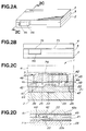
- an exhaust gas sensor 1 consists of a sensor cell unit 2, a pump cell unit 3 and a heater unit 4 which are in the form of a generally rectangular plate and laminated or placed one upon another in this order to constitute an integral body or unit.
- the sensor unit 2 has incorporated therein an oxygen sensor cell 21 in the form of a rectangular plate.
- the oxygen sensor cell 21 has porous electrodes 22 in the place adjacent a longitudinal end and on the opposite side surfaces thereof.
- the pump cell unit 3 has incorporated therein a similar pump cell 41 having similar porous electrodes 42.
- the heater unit 4 is constituted by a known ceramic heater or the like.
- the oxygen sensor cell 21 and oxygen pump cell 41 are made of solid electrolyte having an oxygen ion conductivity.
- a typical example of such solid electrolyte is ZrO 2 having solid solution of Y 2 O 3 or CaO, but a solid solution of another alkaline earth metal or an oxide of rare earth metal and a solid solution of ZrO 2 can be used.
- ZrO 2 which serves as a base metal, may contain HfO 2 .
- the porous electrodes 22 and 42 of the both cells 2 and 3 have a reversible catalytic function (i.e., oxygen dissociating and catalyzing function) for a dissociation reaction for charging oxygen into the solid electrolyte constituting those cells and an oxygen recombining reaction for allowing oxygen to be discharged from the solid electrolyte, and all of them may be, for example, constructed of Pt porous electrodes.
- a reversible catalytic function i.e., oxygen dissociating and catalyzing function
- an oxygen recombining reaction for allowing oxygen to be discharged from the solid electrolyte
- the Au porous electrode is of the kind having a sufficient oxygen dissociating and catalyzing function for activating the oxygen sensor cell 21 and the oxygen pump cell 41, while having a character of being catalytically inactive for the reaction of a detected substance such as methane and oxygen.
- Fig. 1B which is a perspective view taken from the side opposite to that from which Fig. 1A is taken
- the oxygen pump cell 41 is joined, at the side opposite to the sensor cell unit 2, with a detection space forming member 43 which is made of the same solid electrolyte as the oxygen pump cell 41 and in the form of a rectangular plate, while being formed with a window at a portion corresponding to the porous electrode 42, to constitute an integral body or unit.
- the window constitutes the detection space 44.
- the detection space forming member 43 serves as a reinforcement for reinforcing the oxygen pump cell 41 to prevent or restrain bending and expansion thereof.
- an electrode lead 42a is formed on the oxygen pump cell 41 so as to protrude from each porous electrodes 42 toward a longitudinal end of the oxygen pump cell 41 (i.e., an attaching end of the sensor 1), so that the electrode lead 42a is to be connected at the attaching end to an external output lead wire or the like.
- the oxygen pump cell 41 has at opposite ends opposed widthwise thereof and at a location corresponding to the detection space 44 a cut or notched portion 45.
- a porous ceramic member 46 made of Al 2 O 3 or the like and having a number of communication pores is disposed at the notched portion 45 and between the oxygen pump cell 41 and the detection space forming member 43 and constructed so as to introduce therethrough exhaust gas into the detection space 44.
- the porous ceramic member 46 may be disposed between the oxygen pump cell 41 and the detection space forming member 43.
- a base member 23 is joined to the oxygen sensor cell 21 in such a way as to contact the side surface thereof opposite to the detection space forming member 43, to constitute an integral body or unit.
- the base member 23 is formed wider than the oxygen sensor cell 21 and protruded widthwise from the opposite ends of the oxygen sensor cell 21.
- the porous electrode 22 on the side of the oxygen sensor cell 21 confronting the base member 23 is buried or embedded in the base member 23 so that a reference gas is held or stored in the pores or vacant portion of the porous electrode 22. Accordingly, the vacant portion of the porous electrode 22 can be regarded as constituting a reference gas introducing space. Further, as shown in Figs.
- the porous electrode 22 has an integral lead portion 22a, and the above described vacant portion, i.e., the reference gas introducing space of the porous electrode 22 embedded in the base member 23 is communicated by way of the lead portion 22a and at the attaching end of the sensor 1 with the open air.
- a porous communication portion 21a made of porous zirconia, porous alumina or the like, may be provided in a way as to across the oxygen sensor cell 21 in the thickness direction and have an end communicated with the detection space 44, so as to provide communication between the reference gas introducing space and the detection space 44 by way of the porous communication portion 21a and the lead portion 22a.
- the side of the oxygen sensor cell 21 to be joined with the pump cell unit 3 is covered, at least at a portion formed with a semiconductor detection element 25 and except for an area formed with the porous electrode 22, by an insulation layer 28 (refer to Figs. 8B) made of Al 2 O 3 or the like, and the semiconductor detection element 25 in the form of film is formed on the insulation layer 28 at a location adjacent the porous electrode 22.
- the semiconductor detection element 25 is constituted by oxide semiconductor and detects the concentration of a contaminant (detected substance) on the basis of a variation in the electric resistance thereof in proportion to its absorption of the contaminants which are contained in the exhaust gas introduced into the detection space 44.
- the kind of oxide semiconductor differs depending upon the kind of detected substance, for example, for detection of CO or HC, SnO 2 , ZnO, In 2 O 3 and the like are used. Further, for detection of oxides of nitrogen (NO x ), WO 3 is used.
- the pump cell unit 3 is provided with a pair of coupling projections 47 which are made of the same solid electrolyte as the oxygen pump cell 41 to serve as a pump cell side coupling portion.
- the coupling projections 47 are disposed along the opposite ends of the oxygen pump cell 41 opposed widthwise and joined with the same to constitute an integral body or unit.
- a stepped surface formed by the opposite end portions of the base member 23 and the peripheral surface or edge of the oxygen sensor cell 21 serves as or constitute a sensor cell side coupling portion 26.
- adhesive collecting portions 72, 73 and 74 may be formed by partially increasing the clearance 70 at an opening portion 71 opening to the surface of the sensor and the corner portions. More specifically, the collecting portions 72, 73 and 74 are formed by chamfering the base member 23, the corner of the coupling projection 47, and the corner of the oxygen sensor cell 21, respectively. By this, an excess of adhesive is collected at the adhesive collecting portions 72, 73 and 74, so such a trouble in that the adhesive leaks or oozes out from the clearance 70 and sticks to the semiconductor detection element 25 is hard to occur.
- porous electrodes 22 and 42 of the both units 2 and 3 are brought in direct contact with the exhaust gas except one that constitutes the reference gas introducing space, it is desirable to cover them with a porous protective film made of Al 2 O 3 , spinel, ZrO 2 , mullite or the like.
- a green compact 121 corresponding in shape to the oxygen sensor cell 21 (hereinafter referred to as an oxygen sensor cell compact) and a base member compact 123 are prepared separately as shown in Fig. 4, by using a green sheet which is prepared by mixing solid electrolyte powder with binder.
- Fig. 5 shows the oxygen sensor cell compact 121 which is formed with an electrode pattern 122 and lead pattern 122a on the side surface thereof to face or to be associated with the detection space 44.
- the compact 121 is further formed with an electrode pattern 122 and lead pattern 122a on the side surface thereof to face or contact the base member compact 123.
- These patterns are produced by printing of a paste which is prepared by mixing Pt or Au powder selected depending upon the electrode material with a predetermined amount (e.g., 10 wt.% or so ) of ceramic powder which is of the same material as solid electrolyte, and the printed patterns are respectively formed into the porous electrode 22 and the lead portion 22a by firing (refer to Fig. 1).
- the side surfaces of the oxygen sensor cell compact 121 are covered by insulation substance layers 128 (formed into the above described insulation layers 28 after firing) except for an area corresponding to the printed patterns 122 for the porous electrodes, and then lead patterns 125a for forming the lead portions 25a (refer to Fig. 1) of the semiconductor detection element 25 are formed on the insulation substance layer 128.
- the base member compact 123 and the oxygen sensor cell compact 121 are placed one upon another and then fired at a predetermined temperature (for example, 1400 °C ⁇ 1600 °C), whereby the both are joined together and a sintered body 129 as shown in Fig. 7 is obtained.
- Fig. 7 is a sectional view corresponding to that taken along the line 5C-5C in Fig. 5A.
- an element pattern 125 is formed on the sintered body 129 by using a paste containing starting material powder of oxide semiconductor and by being printed on the insulation layer 28 in such a manner as to connect between the respective ends of the two lead portions 25a, and then the sintered body 129 is secondarily sintered at the temperature lower than the sintering temperature of the oxygen sensor cell compact 121, whereby the semiconductor detection element 25 as shown in Fig. 8B is obtained.
- the secondary sintering temperature varies depending upon variations of the material of the oxide semiconductor, e.g., in case of SnO 2 it is set so as to be within the range from 900 °C to 1200 °C.
- the secondary sintering temperature exceeds beyond 1200 °C , volatilization of SnO 2 during sintering becomes prominent, so it is disabled to form a good detection element 25.
- the adherence (joining strength) between the element and oxygen sensor cell becomes insufficient.
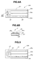
- the semiconductor detection element 25 is shown in Fig. 8A as being formed into a rectangular shape, it can otherwise be formed into an arcuate shape surrounding at least a portion of the porous electrode 22 as shown in Fig. 9.
- the pump cell unit 3 is formed similarly to the sensor cell unit 2. That is, as shown in Fig. 10, compacts 141, 143, 146 and 147 for forming the oxygen pump cell 41, detection space forming member 43, porous ceramic member 46, and coupling projections 47 are prepared independently. Further, as seem from in Figs. 10 and 11, electrode patterns 142 and lead patterns 142a for forming the electrodes 42 and lead portions 42a are formed on the opposite sides of the compact 141 by printing.
- the above described compacts 141, 143, 146 and 147 are placed one upon another in a positional relationship as shown in Fig. 12A, i.e., the compact 143 for the detection space forming member 43 is disposed in such a manner as to allow the electrode pattern 142 of the compact 141 for the oxygen pump cell 41 to be superimposed on the window portion 144 which defines the detection space 44 after firing, and further the compacts 147 for forming the coupling projections 47 are disposed along the respective edges of the compacts 143 opposed widthwise.
- the compact 143 is formed with recesses 149 at a location corresponding to the notched portions 145 of the compact 141 which is formed into notched portions 45 after firing and in such a manner as to allow the opposite ends of the window portion 144 of the compact 143 to be recessed in the thickness direction thereof, and as shown in Fig. 12B the compacts 146 for forming the porous ceramic members 46 are fitted in the recesses 149.
- This laminated assembly is fired at a temperature within the range similar to that of the sensor cell unit, whereby the laminated sections of the assembly are joined together to constitute the pump cell unit 3 as shown in Fig. 13.
- the sensor cell unit 2 and the pump cell unit 3 which are formed in the above manner are adhered by the adhesive 27 as shown in Fig. 3 to constitute an integral body or unit.
- the adhesive 27 made of glass or the like is relatively large, it is desirable, for the purpose of making it hard to occur that the adhesive leaks off and sticks to the semiconductor detection element 25 and the lead portion 25a (refer to Fig. 1), to allow the adhesive to be filled mainly at a location adjacent the peripheral surface of the pump cell 21, and it is further desirable to form one of such adhesive collecting portions 72, 73 an 74 as shown in Figs. 3C.
- the heater unit 4 is similarly adhered to the above described pump cell unit 3 by an adhesive such as glass or the like, to constitute the exhaust gas sensor 1.
- a resistance type heating element is buried or embedded in the heater unit 4 at a portion thereof corresponding in position to the detection space 44 so that the temperature of the heater unit 4 rises easily or readily particularly at or adjacent that portion.
- the adhesive 75 is less likely to stick to the porous electrode 42, the semiconductor detection element 25 or the like within the detection space 44.
- a clearance 76 is formed between the pump cell unit 3 and the heater unit 4, so it becomes possible to allow the exhaust gas EG in the atmosphere to contact the porous electrode 42 on the opposite side of the detection space smoothly.
- the exhaust gas sensor 1 has a threaded portion 51 and an attachment portion 52 and is attached thereat to an exhaust pipe 50.
- the porous electrodes 22 and 42 are connected to the control unit 60 which serves as an oxygen concentration control means by way of the lead portions 22a and 42a (refer to Fig. 1), respectively.
- exhaust gas EG is introduced into the detection space 44 by way of the porous ceramic member 46, so that the concentration of the harmful substances such as CO, HC or the like is detected by the semiconductor element 25.
- the concentration of oxygen in the exhaust gas EG is detected by the oxygen sensor cell 21.
- a constant bias voltage V B is applied across the both porous electrodes 22 of the oxygen sensor cell 21 by means of a power source (not shown) provided within the control unit 60 in such a manner that the detection space 44 side goes negative and the reference gas introducing space side goes positive.
- a pump voltage V P is applied across the both porous electrodes 42 of the oxygen pump cell 41 in such a direction as to cause oxygen to be conveyed or charged from the exhaust gas atmosphere side to the detection space 44 side or in such a direction as to cause oxygen to be conveyed or discharged out of the detection space 44.
- the heater unit 4 heats the oxygen sensor cell 21 and the oxygen pump cell 41 and hold them heated at a predetermined operating temperature (e.g., 300 °C or higher).
- the oxygen contained in the exhaust gas EG is selectively conveyed to the reference gas introducing space side by means of the oxygen sensor cell 21.
- the reference gas introducing space 24 is filled with oxygen gas of the oxygen concentration of nearly 100 %, which oxygen gas is used as a reference gas.
- the exhaust gas EG within the detection space 44 is lower in the oxygen concentration than the above described reference gas, so there is caused a concentration cell electromotive force corresponding to the difference in the oxygen concentration therebetween and in such a direction as to cause current to flow from the reference gas introducing space to the detection space 44.
- the control unit 60 detects the concentration of oxygen in the exhaust gas on the basis of the output voltage V S of the oxygen sensor cell 21 to which the bias voltage V B is applied in addition to the concentration cell voltage and controls the pump voltage V P to be applied to the oxygen pump cell 41 in both directions so as to maintain the concentration of oxygen substantially constant. In the meantime, it is necessary to set the bias voltage V B to be larger than the concentration cell voltage generated in the oxygen sensor cell 21.
- Fig. 15 shows an example of a circuit for the control unit 60.
- the control unit 60 mainly consists of three operational amplifiers 61, 62 and 63, and the terminals P1 and P2 are connected with the respective electrodes 22 of the oxygen sensor cell 21 while the terminals P3 and P4 being connected with the respective electrodes 42 of the oxygen pump cell 41.
- the output voltage V S from the oxygen sensor cell 21 is amplified by a predetermined factor by means of the operational amplifiers 61 and 62 in the preceding section and is thereafter compared with the reference voltage V C by means of the operational amplifier 63 in the succeeding section.
- the operational amplifier 63 outputs the pump voltage V P proportional to the difference between the amplified input voltage V S ' from the oxygen sensor cell 21 and the reference voltage V C .
- V S ' is larger than V C , i.e., in the case the concentration Q S of oxygen in the exhaust gas EG is smaller than the reference concentration Q C that is determined in accordance with the reference voltage V C
- the pump voltage V P is applied in such a direction as to make oxygen be conveyed into the detection space 44, while in the reverse case in such a direction as to make oxygen be conveyed out of the same.
- the concentration of oxygen within the detection space is maintained substantially at a constant value adjacent the reference concentration Q C .
- the control unit 60 can otherwise be constituted by using a microprocessor as a main component so as to carry out the above described control in accordance with a software.
- the detection output of the semiconductor detection element 25 varies depending upon a variation of the concentration of oxygen in exhaust gas and therefore it becomes possible to detect the concentration of contaminants in the exhaust gas with high accuracy.
- the porous electrodes 22 and 42 facing or associated with the detection space 44 are both made of Au which is small in catalytic activity about the reaction of the detected substance such as methane and the like with oxygen, consumption of the above described detected substance in the reaction with oxygen is prevented or restrained, thus similarly contributing to improvement in the accuracy in detection of the above described detected substance.
- the detection substance is methane
- such an electrode has an excellent selectivity in the detection of it. In this instance, a particularly good selectivity in methane is obtained in case the operating temperature of exhaust gas sensor 1 is within the range from 650 °C to 800 °C.
- the control circuit may be structured so as not to apply the bias voltage V B to the oxygen sensor cell 21.
- the sensor cell unit 2 may be formed with an open air communicating portion 30 in the form of a groove for providing communication between the reference gas introducing space 24 and the open air.
- the open air communicating portion 30 is communicated at one end with the reference gas introducing space 24 and at the other end, which opens to an end face of the base member 23, with the open air.
- the heater unit 4 can be joined with the pump cell unit 3 by simultaneous or concurrent firing of them. That is, as shown in Fig. 17, on the surface of a powder compact 150 in the form of a plate, which is produced by compacting ceramic powder together with binder, a resistance heating wire pattern 151 is formed by printing of a paste including resistance heating material powder. On the surface on which the pattern 151 has been formed, another powder compact similarly in the form of plate is placed, and the laminated assembly is fired, whereby the exhaust gas sensor 1 with the heater unit 4 and the pump cell unit 3 joined to constitute an integral body or unit can be obtained.
- the temperature control can be performed with higher accuracy, and the error in the output of the semiconductor detection element can be reduced to improve the reliability and the stability in operation of the exhaust gas sensor 1.
- the porous electrodes 22 and 42 facing or associated with the detection space 44 can be made of Au alloy such as Au-Pd alloy or the like. Further, the electrodes can be made of Ag or Ag alloy such as Ag-Pd alloy. Otherwise, the electrodes can be made of such an alloy that is made lower in the catalytic activity of Pt by adding Au, Ni, Ag or the like metal to Pt. Further, as shown in Fig.
- a porous electrode 100 by first forming a porous electrode main body 101 which is made of Pt, Rh, Pd, Ir or the like metal and then providing a coating 102 made of a catalytically active material such as Au base metal, Ag base metal, oxide such as SnO 2 , ZnO, In 3 O 3 , WO 3 , Bi 2 O 3 or the like to the surface of the main body 101 for contact with exhaust gas.
- a porous electrode main body 101 which is made of Pt, Rh, Pd, Ir or the like metal
- a coating 102 made of a catalytically active material such as Au base metal, Ag base metal, oxide such as SnO 2 , ZnO, In 3 O 3 , WO 3 , Bi 2 O 3 or the like to the surface of the main body 101 for contact with exhaust gas.
- the above described coating 102 may be formed by a method of applying a paste containing particles of the above described catalytically inactive material to the main body 101 and firing the paste secondarily as shown in Fig. 21B or by a vapor-phase film forming method such as vapor deposition, sputtering or the like as shown in Figs. 21C.
- the porous main body 101 is formed so as to have a number of intricate pores P, so such a case may possibly occur in which the coating 102 is not formed so as to intrude deeply into the pores P.
- the catalytic activity about the reaction of the detected substance and oxygen can be made sufficiently small, it does not matter that the electrode has such a portion not coated.
- the porous electrode facing or associated with the detection space 44 is made of another material suited for detection of the detected substance or the operating temperature of the sensor is changed so as to be suited for selective detection of the substance desired to be detected. In the latter case, solid electrolyte suited for the operating temperature is used if necessary.
- FIG. 2A to 2C An example of the exhaust gas sensor 1 shown in Figs. 2A to 2C was produced according to the above described method.
- the solid electrolyte is ZrO 2 having a solid solution of Y 2 O 3
- the detection space 44 is 0.003 cm 3 in volume
- each electrode 42 of the pump cell 41 is 0.08 cm 2 in area and 10 ⁇ m thick
- each electrode 22 of the oxygen sensor cell 21 is 0.02 cm 2 and 10 ⁇ m thick.
- examples in which a disk-shaped porous electrode of 8 mm in diameter and made of Au or Pt were prepared.
- the examples were disposed within a tubular receptacle having a gas inlet and outlet and heated up to 750 °C. Under this condition, a test gas containing 300 ppm oxygen, 350 ppm methane and the remainder of Ar was charged through the inlet at the flow rate of 100 ml/min. and discharged through the outlet to measure the decrease percentage as to the concentration of methane in the test gas.
- the decrease percentage as to the concentration of oxygen reached 30 %, so it was recognized that the catalytic activity for the reaction of methane and oxygen was large.
- the above described decrease percentage as to the concentration of methane was less than 10 %, so it was confirmed that the example was catalytically inactive about the above reaction.
- the above described exhaust gas sensor was installed on the exhaust pipe and each terminals thereof were connected to the control unit shown in Figs. 14 and 15.
- the exhaust gas sensor 1 was heated up to 750 °C, and various measured gases consisting of various concentrations of oxygen in the range from 50 to 5000 ppm, various concentrations of detected substance in the range from 0 to 500 ppm and the remainder of nitrogen were conducted through the exhaust pipe at the flow rate of 12 l/min. to measure the resistance of the semiconductor element.
- selected as the detected substance is either of methane (CH 4 ), propylene (C 3 H 6 ), carbon monoxide (CO) or nitrogen monoxide (NO).
- Figs. 18A and 18B are the graphs showing the detection result of the resistance of the semiconductor element 25 in relation to the concentration of oxygen in the measured or tested gas, resulting when the concentration of oxygen is varied variously within the above described range, with respect to the cases the concentration of oxygen in the detection space 44 is controlled or not.
- Fig. 18A shows the result obtained when Pt porous electrodes were used for the electrodes 22 and 42 on the detection space 44 side
- Fig. 18B shows the result obtained when Au porous electrodes were used.
- the resistance of the semiconductor detection element 25 varies depending upon a variation of the concentration of oxygen in the test gas when the control by the control unit 60 is not carried out, whereas when the control is carried out, the resistance becomes substantially constant, so it is seen that the concentration of oxygen in the detection space 44 is maintained substantially constant. Further, it is indicated or meant by this that both of the Pt porous electrode and Au porous electrode have an excellent oxygen dissociating and catalyzing function.
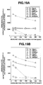
- Figs. 19A and 19B are graphs in which the detection result of the resistance of the semiconductor detection element 25 resulting when both of the methane concentration and oxygen concentration are varied variously within the above described range, is represented by lines for each oxygen concentrations in relation to the concentration of methane in the measured or tested gas and with respect to the cases the concentration of oxygen in the detection space 44 is controlled or not.
- Figs. 19A shows the result obtained when Pt porous electrodes are used for the electrodes 22 and 42 on the detection space 44 side
- Fig. 19B shows the result obtained when Au porous electrodes are used.
- the solid lines in the graphs represent the case where the control is made on the concentration of oxygen in the detection space 44 according to the present invention, whereas the dotted lines represent the case where the control is not made.
- Fig. 20 is a graph showing the resistance of the semiconductor element 25 in relation to the concentration of various detected substance when the Au porous electrodes are used in the sensor and the measured gas is changed variously. From the graph, it is seen that the resistance of the semiconductor element 25 in the sensor varies largely in case the detected substance is methane, so the sensor is excellent in the selectivity of detection of methane.
Applications Claiming Priority (6)
| Application Number | Priority Date | Filing Date | Title |
|---|---|---|---|
| JP9061796 | 1996-03-19 | ||
| JP90617/96 | 1996-03-19 | ||
| JP9061796 | 1996-03-19 | ||
| JP14779/97 | 1997-01-10 | ||
| JP1477997 | 1997-01-10 | ||
| JP01477997A JP3521170B2 (ja) | 1996-03-19 | 1997-01-10 | 排気ガスセンサ及びそれを用いたセンサシステム |
Publications (2)
| Publication Number | Publication Date |
|---|---|
| EP0797094A2 true EP0797094A2 (de) | 1997-09-24 |
| EP0797094A3 EP0797094A3 (de) | 2000-04-05 |
Family
ID=26350793
Family Applications (1)
| Application Number | Title | Priority Date | Filing Date |
|---|---|---|---|
| EP97104603A Withdrawn EP0797094A3 (de) | 1996-03-19 | 1997-03-18 | Abgassensor |
Country Status (3)
| Country | Link |
|---|---|
| US (1) | US5993625A (de) |
| EP (1) | EP0797094A3 (de) |
| JP (1) | JP3521170B2 (de) |
Cited By (8)
| Publication number | Priority date | Publication date | Assignee | Title |
|---|---|---|---|---|
| GB2334785A (en) * | 1998-02-27 | 1999-09-01 | Siemens Ag | Gas sensor |
| US6153072A (en) * | 1997-09-09 | 2000-11-28 | Ngk Spark Plug Co., Ltd. | Gas sensor, gas sensor system using the same, and method of manufacturing a gas sensor |
| US6303012B1 (en) | 1997-09-22 | 2001-10-16 | Ngk Spark Plug Co., Ltd. | Gas sensor, gas sensor system using the same |
| US6337006B1 (en) | 1999-02-08 | 2002-01-08 | Ngk Spark Plug Co., Ltd. | Lanthanum gallate sintered body |
| EP0897112A3 (de) * | 1997-08-14 | 2002-03-27 | NGK Spark Plug Co. Ltd. | Gassensor |
| EP1178304A3 (de) * | 2000-08-04 | 2002-05-22 | Ngk Insulators, Ltd. | Vorrichtung und Verfahren zur Detektion von Sauerstoffspuren |
| EP1217361A2 (de) * | 2000-12-22 | 2002-06-26 | Siemens Aktiengesellschaft | Mehrstufiger Gassensor, Betriebs- und Herstellungsverfahren |
| EP2927677A1 (de) * | 2014-03-31 | 2015-10-07 | NGK Insulators, Ltd. | Gassensor |
Families Citing this family (18)
| Publication number | Priority date | Publication date | Assignee | Title |
|---|---|---|---|---|
| DE19750123C2 (de) * | 1997-11-13 | 2000-09-07 | Heraeus Electro Nite Int | Verfahren zur Herstellung einer Sensoranordnung für die Temperaturmessung |
| JP3560316B2 (ja) * | 1998-11-25 | 2004-09-02 | 日本特殊陶業株式会社 | ガスセンサとその製造方法及びガスセンサシステム |
| JP3540177B2 (ja) * | 1998-12-04 | 2004-07-07 | 日本特殊陶業株式会社 | ガスセンサ及びそれを用いた可燃性ガス成分濃度測定装置 |
| WO2001041508A1 (fr) * | 1999-11-30 | 2001-06-07 | Ibiden Co., Ltd. | Appareil chauffant en ceramique |
| JP2002116172A (ja) * | 2000-10-10 | 2002-04-19 | Ngk Spark Plug Co Ltd | 湿度センサ |
| US7017389B2 (en) * | 2002-04-20 | 2006-03-28 | The Research Foundation Of Suny At Stony Brook | Sensors including metal oxides selective for specific gases and methods for preparing same |
| US8485983B2 (en) * | 2003-04-21 | 2013-07-16 | The Research Foundation Of State University Of New York | Selective nanoprobe for olfactory medicine |
| JP2005300470A (ja) * | 2004-04-15 | 2005-10-27 | Denso Corp | 積層型ガスセンサ素子の製造方法 |
| DE202005002060U1 (de) * | 2005-02-09 | 2006-06-14 | Liebherr-Werk Lienz Gmbh | Kühl- und/oder Gefriergerät mit Eiswürfelbereiter |
| US20070089501A1 (en) * | 2005-09-30 | 2007-04-26 | Endicott Dennis L | Method for monitoring exhaust gas condensates |
| JP4795874B2 (ja) * | 2006-07-05 | 2011-10-19 | 日本特殊陶業株式会社 | ガスセンサ素子およびそれを用いたガスセンサ、ガスセンサ素子の製造方法 |
| US20080128274A1 (en) * | 2006-12-04 | 2008-06-05 | Honeywell International Inc. | Nanostructured sensor for high temperature applications |
| JP5209401B2 (ja) * | 2008-08-07 | 2013-06-12 | 日本特殊陶業株式会社 | マルチガスセンサ及びガスセンサ制御装置 |
| JP4999894B2 (ja) | 2009-08-17 | 2012-08-15 | 日本碍子株式会社 | ガスセンサ |
| US20120237968A1 (en) | 2011-03-14 | 2012-09-20 | Anastasia Rigas | Detector and Method for Detection of H. Pylori |
| JP5724832B2 (ja) * | 2011-11-07 | 2015-05-27 | トヨタ自動車株式会社 | 酸素濃度センサ |
| EP3145403A4 (de) | 2012-03-14 | 2018-01-24 | Anastasia Rigas | Atemanalysevorrichtung und atemtestverfahren |
| US10176696B2 (en) * | 2014-11-21 | 2019-01-08 | Richard Harper | Apparatus and process for measuring gaseous emissions from an engine |
Citations (6)
| Publication number | Priority date | Publication date | Assignee | Title |
|---|---|---|---|---|
| US4578171A (en) * | 1983-12-15 | 1986-03-25 | Ngk Spark Plug Co., Ltd. | Air/fuel ratio detector |
| US4601809A (en) * | 1984-04-16 | 1986-07-22 | Nissan Motor Co., Ltd. | Oxygen concentration detecting system using oxygen sensor including oxygen ion pump |
| US4609452A (en) * | 1984-02-08 | 1986-09-02 | Mitsubishi Denki Kabushiki Kaisha | Engine air/fuel ratio sensing device |
| US4615787A (en) * | 1983-12-15 | 1986-10-07 | Mitsubishi Denki NGK Spark Plug Co. Ltd. | Air/fuel ratio detector |
| US5413683A (en) * | 1993-03-25 | 1995-05-09 | Ngk Insulators Ltd. | Oxygen sensing apparatus and method using electrochemical oxygen pumping action to provide reference gas |
| EP0743431A2 (de) * | 1995-04-19 | 1996-11-20 | Ngk Insulators, Ltd. | Verfahren und Vorrichtung zum Feststellen der Verschlechterung eines Abgaskatalysators |
Family Cites Families (12)
| Publication number | Priority date | Publication date | Assignee | Title |
|---|---|---|---|---|
| JPS5348594A (en) * | 1976-10-14 | 1978-05-02 | Nissan Motor | Oxygen sensor |
| US4578172A (en) * | 1983-12-15 | 1986-03-25 | Ngk Spark Plug Co. | Air/fuel ratio detector |
| EP0147989A3 (de) * | 1983-12-17 | 1985-08-14 | NGK Spark Plug Co. Ltd. | Messfühler zum Messen des Luft-Kraftstoff-Verhältnisses |
| GB2183042B (en) * | 1985-09-27 | 1989-09-20 | Ngk Spark Plug Co | Air/fuel ratio sensor |
| JPH0814570B2 (ja) * | 1986-02-07 | 1996-02-14 | 日本特殊陶業株式会社 | 空燃比センサ |
| US5250169A (en) * | 1991-06-07 | 1993-10-05 | Ford Motor Company | Apparatus for sensing hydrocarbons and carbon monoxide |
| DE4311849C2 (de) * | 1992-12-23 | 2003-04-24 | Bosch Gmbh Robert | Sensor zur Bestimmung von Gaskomponenten und/oder Gaskonzentrationen von Gasgemischen |
| DE4243733C2 (de) * | 1992-12-23 | 2003-03-27 | Bosch Gmbh Robert | Sensor zur Bestimmung von Gaskomponenten und/oder Gaskonzentrationen von Gasgemischen |
| DE4311851A1 (de) * | 1993-04-10 | 1994-10-13 | Bosch Gmbh Robert | Sensoranordnung zur Bestimmung von Gaskomponenten und/oder von Gaskonzentrationen von Gasgemischen |
| DE4333232B4 (de) * | 1993-09-30 | 2004-07-01 | Robert Bosch Gmbh | Meßfühler zur Bestimmung des Sauerstoffgehaltes von Gasgemischen |
| US5672811A (en) * | 1994-04-21 | 1997-09-30 | Ngk Insulators, Ltd. | Method of measuring a gas component and sensing device for measuring the gas component |
| JPH08122287A (ja) * | 1994-10-24 | 1996-05-17 | Ngk Insulators Ltd | ガス成分の濃度の測定装置および方法 |
-
1997
- 1997-01-10 JP JP01477997A patent/JP3521170B2/ja not_active Expired - Fee Related
- 1997-03-18 EP EP97104603A patent/EP0797094A3/de not_active Withdrawn
- 1997-03-19 US US08/820,522 patent/US5993625A/en not_active Expired - Fee Related
Patent Citations (6)
| Publication number | Priority date | Publication date | Assignee | Title |
|---|---|---|---|---|
| US4578171A (en) * | 1983-12-15 | 1986-03-25 | Ngk Spark Plug Co., Ltd. | Air/fuel ratio detector |
| US4615787A (en) * | 1983-12-15 | 1986-10-07 | Mitsubishi Denki NGK Spark Plug Co. Ltd. | Air/fuel ratio detector |
| US4609452A (en) * | 1984-02-08 | 1986-09-02 | Mitsubishi Denki Kabushiki Kaisha | Engine air/fuel ratio sensing device |
| US4601809A (en) * | 1984-04-16 | 1986-07-22 | Nissan Motor Co., Ltd. | Oxygen concentration detecting system using oxygen sensor including oxygen ion pump |
| US5413683A (en) * | 1993-03-25 | 1995-05-09 | Ngk Insulators Ltd. | Oxygen sensing apparatus and method using electrochemical oxygen pumping action to provide reference gas |
| EP0743431A2 (de) * | 1995-04-19 | 1996-11-20 | Ngk Insulators, Ltd. | Verfahren und Vorrichtung zum Feststellen der Verschlechterung eines Abgaskatalysators |
Cited By (12)
| Publication number | Priority date | Publication date | Assignee | Title |
|---|---|---|---|---|
| EP0897112A3 (de) * | 1997-08-14 | 2002-03-27 | NGK Spark Plug Co. Ltd. | Gassensor |
| US6153072A (en) * | 1997-09-09 | 2000-11-28 | Ngk Spark Plug Co., Ltd. | Gas sensor, gas sensor system using the same, and method of manufacturing a gas sensor |
| US6303012B1 (en) | 1997-09-22 | 2001-10-16 | Ngk Spark Plug Co., Ltd. | Gas sensor, gas sensor system using the same |
| US6554984B2 (en) | 1997-09-22 | 2003-04-29 | Ngk Spark Plug Co., Ltd. | Method of manufacturing a gas sensor |
| GB2334785A (en) * | 1998-02-27 | 1999-09-01 | Siemens Ag | Gas sensor |
| FR2775521A1 (fr) * | 1998-02-27 | 1999-09-03 | Siemens Ag | Detecteur de gaz a comportement de reponse ameliore |
| US6337006B1 (en) | 1999-02-08 | 2002-01-08 | Ngk Spark Plug Co., Ltd. | Lanthanum gallate sintered body |
| EP1178304A3 (de) * | 2000-08-04 | 2002-05-22 | Ngk Insulators, Ltd. | Vorrichtung und Verfahren zur Detektion von Sauerstoffspuren |
| EP1217361A2 (de) * | 2000-12-22 | 2002-06-26 | Siemens Aktiengesellschaft | Mehrstufiger Gassensor, Betriebs- und Herstellungsverfahren |
| EP1217361A3 (de) * | 2000-12-22 | 2004-05-19 | Siemens Aktiengesellschaft | Mehrstufiger Gassensor, Betriebs- und Herstellungsverfahren |
| EP2927677A1 (de) * | 2014-03-31 | 2015-10-07 | NGK Insulators, Ltd. | Gassensor |
| US9804118B2 (en) | 2014-03-31 | 2017-10-31 | Ngk Insulators, Ltd. | Gas sensor |
Also Published As
| Publication number | Publication date |
|---|---|
| JPH09311120A (ja) | 1997-12-02 |
| JP3521170B2 (ja) | 2004-04-19 |
| EP0797094A3 (de) | 2000-04-05 |
| US5993625A (en) | 1999-11-30 |
Similar Documents
| Publication | Publication Date | Title |
|---|---|---|
| US5993625A (en) | Exhaust gas sensor | |
| US7153412B2 (en) | Electrodes, electrochemical elements, gas sensors, and gas measurement methods | |
| US9304102B2 (en) | Amperometric electrochemical sensors, sensor systems and detection methods | |
| KR101851281B1 (ko) | 암모니아 센서 | |
| EP0851225B1 (de) | Abgassensorsystem | |
| EP0259175B1 (de) | Elektrochemischer Gassensor und Verfahren zu seiner Herstellung | |
| EP0880026B1 (de) | Gassensor | |
| EP0188900B1 (de) | Elektrochemische Vorrichtung | |
| EP0867715B1 (de) | Gassensor | |
| EP0845669B1 (de) | Luft-/Kraftstoffverhältnissensor über einen breiten Bereich mit einer elektrochemischen Zelle und Verfahren zur Detektion von zwei Arten von Luft/Kraftstoffverhältnissen unter Verwendung dieses Sensors | |
| US8974657B2 (en) | Amperometric electrochemical cells and sensors | |
| US20090218220A1 (en) | Amperometric Electrochemical Cells and Sensors | |
| US5861092A (en) | Nitrogen oxide detector | |
| EP0294085B1 (de) | Elektrochemische Elemente | |
| US20020108854A1 (en) | Gas sensor | |
| US20030116448A1 (en) | Gas sensor element, production method, and reconditioning method thereof | |
| JP3587290B2 (ja) | NOxガスセンサ | |
| EP0227257B1 (de) | Elektrochemische Vorrichtung | |
| KR102370434B1 (ko) | 전류측정 전기화학 센서, 센서 시스템 및 검출 방법 (Amperometric electrochemical sensors, sensor systems and detection methods) | |
| JP2003518619A (ja) | ガス成分を測定するためのガスセンサーのセンサー素子 | |
| JP3587282B2 (ja) | 窒素酸化物濃度検出器 | |
| US6797138B1 (en) | Gas senior design and method for forming the same | |
| JP3556790B2 (ja) | 排気ガスセンサ及び排気ガスセンサシステム | |
| JP3943262B2 (ja) | NOxガス濃度測定装置及びNOxガス濃度測定方法 | |
| JPH11118758A (ja) | 排気ガスセンサ及び排気ガスセンサシステム |
Legal Events
| Date | Code | Title | Description |
|---|---|---|---|
| PUAI | Public reference made under article 153(3) epc to a published international application that has entered the european phase |
Free format text: ORIGINAL CODE: 0009012 |
|
| AK | Designated contracting states |
Kind code of ref document: A2 Designated state(s): DE FR GB IT SE |
|
| PUAL | Search report despatched |
Free format text: ORIGINAL CODE: 0009013 |
|
| AK | Designated contracting states |
Kind code of ref document: A3 Designated state(s): DE FR GB IT SE |
|
| RIC1 | Information provided on ipc code assigned before grant |
Free format text: 7G 01N 27/407 A, 7G 01N 27/419 B, 7G 01N 27/406 B |
|
| STAA | Information on the status of an ep patent application or granted ep patent |
Free format text: STATUS: THE APPLICATION IS DEEMED TO BE WITHDRAWN |
|
| 18D | Application deemed to be withdrawn |
Effective date: 20001006 |