EP0743431A2 - Verfahren und Vorrichtung zum Feststellen der Verschlechterung eines Abgaskatalysators - Google Patents
Verfahren und Vorrichtung zum Feststellen der Verschlechterung eines Abgaskatalysators Download PDFInfo
- Publication number
- EP0743431A2 EP0743431A2 EP96302665A EP96302665A EP0743431A2 EP 0743431 A2 EP0743431 A2 EP 0743431A2 EP 96302665 A EP96302665 A EP 96302665A EP 96302665 A EP96302665 A EP 96302665A EP 0743431 A2 EP0743431 A2 EP 0743431A2
- Authority
- EP
- European Patent Office
- Prior art keywords
- oxygen
- exhaust gas
- processing zone
- pumping
- combustion exhaust
- Prior art date
- Legal status (The legal status is an assumption and is not a legal conclusion. Google has not performed a legal analysis and makes no representation as to the accuracy of the status listed.)
- Granted
Links
Images


Classifications
-
- F—MECHANICAL ENGINEERING; LIGHTING; HEATING; WEAPONS; BLASTING
- F01—MACHINES OR ENGINES IN GENERAL; ENGINE PLANTS IN GENERAL; STEAM ENGINES
- F01N—GAS-FLOW SILENCERS OR EXHAUST APPARATUS FOR MACHINES OR ENGINES IN GENERAL; GAS-FLOW SILENCERS OR EXHAUST APPARATUS FOR INTERNAL COMBUSTION ENGINES
- F01N11/00—Monitoring or diagnostic devices for exhaust-gas treatment apparatus, e.g. for catalytic activity
- F01N11/007—Monitoring or diagnostic devices for exhaust-gas treatment apparatus, e.g. for catalytic activity the diagnostic devices measuring oxygen or air concentration downstream of the exhaust apparatus
-
- G—PHYSICS
- G01—MEASURING; TESTING
- G01N—INVESTIGATING OR ANALYSING MATERIALS BY DETERMINING THEIR CHEMICAL OR PHYSICAL PROPERTIES
- G01N27/00—Investigating or analysing materials by the use of electric, electrochemical, or magnetic means
- G01N27/26—Investigating or analysing materials by the use of electric, electrochemical, or magnetic means by investigating electrochemical variables; by using electrolysis or electrophoresis
- G01N27/416—Systems
- G01N27/417—Systems using cells, i.e. more than one cell and probes with solid electrolytes
- G01N27/419—Measuring voltages or currents with a combination of oxygen pumping cells and oxygen concentration cells
-
- F—MECHANICAL ENGINEERING; LIGHTING; HEATING; WEAPONS; BLASTING
- F01—MACHINES OR ENGINES IN GENERAL; ENGINE PLANTS IN GENERAL; STEAM ENGINES
- F01N—GAS-FLOW SILENCERS OR EXHAUST APPARATUS FOR MACHINES OR ENGINES IN GENERAL; GAS-FLOW SILENCERS OR EXHAUST APPARATUS FOR INTERNAL COMBUSTION ENGINES
- F01N2550/00—Monitoring or diagnosing the deterioration of exhaust systems
- F01N2550/02—Catalytic activity of catalytic converters
-
- Y—GENERAL TAGGING OF NEW TECHNOLOGICAL DEVELOPMENTS; GENERAL TAGGING OF CROSS-SECTIONAL TECHNOLOGIES SPANNING OVER SEVERAL SECTIONS OF THE IPC; TECHNICAL SUBJECTS COVERED BY FORMER USPC CROSS-REFERENCE ART COLLECTIONS [XRACs] AND DIGESTS
- Y02—TECHNOLOGIES OR APPLICATIONS FOR MITIGATION OR ADAPTATION AGAINST CLIMATE CHANGE
- Y02T—CLIMATE CHANGE MITIGATION TECHNOLOGIES RELATED TO TRANSPORTATION
- Y02T10/00—Road transport of goods or passengers
- Y02T10/10—Internal combustion engine [ICE] based vehicles
- Y02T10/40—Engine management systems
-
- Y—GENERAL TAGGING OF NEW TECHNOLOGICAL DEVELOPMENTS; GENERAL TAGGING OF CROSS-SECTIONAL TECHNOLOGIES SPANNING OVER SEVERAL SECTIONS OF THE IPC; TECHNICAL SUBJECTS COVERED BY FORMER USPC CROSS-REFERENCE ART COLLECTIONS [XRACs] AND DIGESTS
- Y10—TECHNICAL SUBJECTS COVERED BY FORMER USPC
- Y10T—TECHNICAL SUBJECTS COVERED BY FORMER US CLASSIFICATION
- Y10T436/00—Chemistry: analytical and immunological testing
- Y10T436/20—Oxygen containing
- Y10T436/207497—Molecular oxygen
- Y10T436/208339—Fuel/air mixture or exhaust gas analysis
Definitions
- the present invention relates in general to a method and a system for detecting deterioration of an exhaust gas control or purification catalyst.
- the invention is concerned with such method and system for detecting the deterioration of a catalyst which is adapted to purify a combustion exhaust gas emitted by internal combustion engines of automobiles, and which catalyst is provided in an exhaust emission passage through which the combustion exhaust gas including combustible gas components is discharged.
- the present invention further relates to a method and an apparatus for measuring the concentration of residual oxygen remaining in the combustion exhaust gas.
- a catalyst such as a three way catalyst or an oxidizing catalyst, which is adapted to oxidize and remove combustible gas components included in the combustion exhaust gas.
- a catalyst tends to deteriorate during a long period of use depending upon its operating condition.
- catalytic poison components present in the combustion exhaust gas undesirably deteriorate the catalyst.
- the deterioration of the catalyst results in reduction in its efficiency for purifying the exhaust combustion gas, i.e., catalytic conversion efficiency.
- the apparatus disclosed in the publication includes: means for detecting the temperatures of the exhaust gas at an inlet and an outlet of the catalyst, respectively; means for detecting the operating condition of the engine; and means for determining that the catalyst is deteriorated when a difference between the inlet and outlet temperatures of the exhaust gas respectively detected before and after its passage through the catalyst is smaller than a predetermined value, which is determined depending upon the operating condition of the engine.
- an oxygen sensing apparatus for measuring the concentration of oxygen in a combustion exhaust gas which includes: an electrochemical oxygen pumping cell; an oxygen concentration cell; and diffusion control means.
- a subject gas in the form of the combustion exhaust gas is introduced into a measuring space in the apparatus under a predetermined diffusion resistance determined by the diffusion control means.
- the pumping cell is adapted to pump out oxygen from the measuring space and pump in oxygen into the measuring space, such that an electromotive force detected by the oxygen concentration cell is held at a constant level.
- the thus constructed sensing apparatus is adapted to measure a pumping current which keeps the concentration of oxygen within the measuring space at a constant value.
- combustible gas components such as hydrogen, carbon monoxide or hydrocarbon if included in the subject gas (e.g.. combustion exhaust gas) may react with oxygen in the measuring space so as to reduce an amount of oxygen included in the combustion exhaust gas, deteriorating the accuracy of measurement of the oxygen concentration in the exhaust gas.
- the present invention was developed to solve the drawbacks of the known method and apparatus for measuring the oxygen concentration in the combustion exhaust gas. It is therefore a first object of the present invention to provide a method and a system for detecting, with a single sensor, the deterioration of the catalyst with high accuracy in an actual running state of the vehicle, without an influence of heat capacity of the exhaust system including the catalyst.
- the invention provides a method of detecting deterioration of an exhaust gas control catalyst provided in an exhaust gas passage through which a combustion exhaust gas containing a combustible gas component is discharged, comprising the steps of: introducing the combustion exhaust gas which has passed through the catalyst into a processing zone under a predetermined diffusion resistance; energizing an electrochemical oxygen pumping cell to perform an oxygen pumping action for pumping oxygen out of the processing zone to thereby control an oxygen concentration in the combustion exhaust gas within the processing zone to a predetermined value at which the combustible gas component cannot be substantially burned; detecting a pumping current flowing through the electrochemical oxygen pumping cell during energization of the electrochemical pumping cell; and determining a degree of deterioration of the catalyst according to an oxygen concentration in the combustion exhaust gas which is obtained on the basis of the detected pumping current.
- the invention provides a system for detecting deterioration of an exhaust gas control catalyst provided in an exhaust gas passage through which a combustion exhaust gas containing a combustible gas component is discharged, comprising: a processing zone communicating with a portion of the exhaust gas passage which is downstream of the catalyst as viewed in a direction of flow of the exhaust gas; diffusion control means for introducing, under a predetermined diffusion resistance, the combustion exhaust gas which has passed through the catalyst into the processing zone; an electrochemical oxygen pumping cell including an oxygen ion conductive solid electrolyte layer which partially defines the processing zone, and a pair of electrodes which are disposed in contact with the oxygen ion conductive solid electrolyte layer and one of which is exposed to the processing zone, the electrochemical oxygen pumping cell being energized to perform an oxygen pumping action for pumping oxygen out of the processing zone to thereby control an oxygen concentration in an atmosphere within the processing zone to a predetermined value at which the combustible gas component cannot be substantially burned; detecting means for detecting detecting deterioration
- one of electrodes which is exposed to the processing zone is formed of an electrode material which has substantially no or a small degree of function as an oxidizing catalyst.
- the invention provides a method of measuring a concentration of oxygen in a combustion exhaust gas containing a combustible gas component, comprising the steps of: introducing the combustion exhaust gas into a processing zone under a predetermined diffusion resistance; energizing an electrochemical oxygen pumping cell to perform an oxygen pumping action for pumping oxygen out of the processing zone to thereby control an oxygen concentration in the combustion exhaust gas within the processing zone to a predetermined value at which the combustible gas component cannot be substantially burned; detecting a pumping current flowing through the electrochemical oxygen pumping cell during energization of the electrochemical pumping cell; and obtaining an oxygen concentration in the combustion exhaust gas on the basis of the detected pumping current.
- the invention provides an apparatus for measuring a concentration of oxygen in a combustion exhaust gas containing a combustible gas component, comprising: a processing zone communicating with an exhaust gas passage through which the combustion exhaust gas is discharged; diffusion control means for introducing the combustion exhaust gas from the exhaust gas passage into the processing zone under a predetermined diffusion resistance; an electrochemical oxygen pumping cell including an oxygen ion conductive solid electrolyte layer which partially defines the processing zone, and a pair of electrodes which are disposed in contact with the oxygen ion conductive solid electrolyte layer and one of which is exposed to the processing zone, the electrochemical oxygen pumping cell being energized to perform an oxygen pumping action for pumping oxygen out of the processing zone to thereby control an oxygen concentration in an atmosphere within the processing zone to a predetermined value at which the combustible gas component cannot be substantially burned; and detecting means for detecting a pumping current flowing through the electrochemical oxygen pumping cell, during energization of the electrochemical oxygen pumping cell.
- one of electrodes which is exposed to the processing zone is formed of an electrode material which has substantially no or a small degree of function as an oxidizing catalyst.
- the electrochemical oxygen pumping cell which includes the oxygen ion conductive solid electrolyte layer and a pair of electrodes disposed in contact with the electrolyte layer is energized to perform the oxygen pumping action at a suitable temperature, so that the oxygen partial pressure in the atmosphere which is in contact with one of the pair of electrodes (i.e., cathode) is controlled to a predetermined level which is low enough to inhibit a reaction of oxygen with the combustible gas components existing in the subject gas. Accordingly, the amount of oxygen in the subject gas can be accurately obtained by measuring the electric current flowing between the pair of electrodes.
- the electrochemical oxygen pumping cell performs the pumping action for establishing a condition wherein the reaction of oxygen with the combustible gas components existing in the combustion exhaust gas as the subject gas is inhibited.
- the pumping current flowing between the pair of electrodes is detected to obtain the concentration of residual oxygen remaining in the combustion exhaust gas, when the oxygen concentration is controlled as described above.
- the present invention makes it possible to accurately detect the degree of deterioration of the exhaust gas control or purification catalyst, on the basis of the obtained oxygen concentration.
- a sensing element 2 of the conventional oxygen sensor having an integral laminar structure including a plurality of oxygen ion conductive solid electrolyte layers.
- an internal space 4 as a measuring space which is in communication with an external subject gas space through an orifice 6, which functions as a diffusion control passage having a predetermined diffusion resistance.
- an outer pumping electrode 8 and an inner pumping electrode 10 are provided on the opposite major surfaces of the solid electrolyte layer through which the orifice 6 is formed, so that the above-indicated solid electrolyte layer and the electrodes 8, 10 constitute an electrochemical oxygen pumping cell.
- the sensing element 2 also has a reference air passage 12 as shown in Fig 1.
- a reference electrode 14 and a measuring electrode 16 On the opposite surfaces of the solid electrolyte layer which partially defines the internal space 4 and the reference air passage 12, there are provided a reference electrode 14 and a measuring electrode 16, so that the above-indicated solid electrolyte layer and the electrodes 14, 16 constitute an electrochemical oxygen sensing cell.
- the subject gas is introduced from the external subject gas space into the internal space 4 through the orifice 6 under the predetermined diffusion resistance.
- the oxygen pumping cell is energized to perform an oxygen pumping action for pumping oxygen out of the internal space 4, at a voltage supplied from a variable-voltage power source 18, which voltage is controlled such that a voltage (monitor voltage) of the oxygen sensing cell is held at a constant level.
- the operation of the sensing element 2 of the conventional oxygen sensor provides a relationship characteristic of a pumping current (mA) and a monitor voltage (V), as represented by the graph of Fig. 2, as well known in the art.
- the pumping current increases proportionally to an increase in the monitor voltage (V) corresponding to an electromotive force which is induced between the reference and measuring electrodes 14 and 16 according to a difference in the oxygen concentration between the atmosphere within the internal space 4 and the reference air within the reference air passage 12.
- V monitor voltage
- the amount of oxygen which is introduced into the internal space 4 through the orifice 6 as the diffusion control passage is larger than the amount of oxygen which is pumped out from the internal space 4 into the external subject gas space by the oxygen pumping cell.
- This second range “II” is referred to as a "current limiting range” in which the amount of oxygen which is introduced through the orifice 6 into the internal space 4 is substantially equal to the amount of oxygen which is pumped out into the external space by the oxygen pumping cell.
- the conventional oxygen sensing apparatus is operated in this second range II so as to detect the pumping current (limiting current) flowing between the two pumping electrodes 8, 10.
- the oxygen concentration in the subject gas is obtained on basis of the detected pumping current since the pumping current in this second range II is proportional to the oxygen concentration in the subject gas.
- the pumping current and monitor voltage characteristic fluctuated as shown in the graph of Fig. 3, depending upon the presence of combustible gas components included in the subject gas and the degree of the oxygen concentration in the subject gas.
- a curve indicated by "a” represents a relationship between the monitor voltage and the pumping current, which was obtained when the subject gas included no combustible gas components
- a curve indicated by “b” represents a relationship between the monitor voltage and the pumping current, which was obtained when the subject gas included the combustible gas components.
- the pumping current of the subject gas as represented by the curve "b” is considerably lower than that of the subject gas as represented by the curve "a", in the second range II. This means that, in the second range II, the pumping current is greatly influenced by the presence of the combustible gas components included in the subject gas.
- the pumping currents as represented by the two curves "a" and "b" are similarly increased with an increase of the monitor voltage.
- the pumping current is completely free from the influence of the combustible gas components included in the subject gas. That is, in the third range III, it is possible to obtain the pumping current which accurately reflects the oxygen concentration in the subject gas, regardless of the presence of the combustible gas components in the subject gas.
- a curve "c" indicates a relationship between the monitor voltage and the pumping current, which was obtained when the subject gas had a higher oxygen concentration than the subject gas as represented by the curve "a".
- the subject gas of the curve "c” included no combustible gas components.
- the pumping current in the subject gas of the curve "c” is higher than that in the subject gas of the curve "a", in the third range III.
- the pumping current varies in proportion to the change in the monitor voltage depending upon the oxygen concentration in the subject gas.
- it is possible to obtain the oxygen concentration in the subject gas by detecting the pumping current in the third range III, on the basis of a predetermined relationship between the pumping current and the oxygen concentration.
- the present invention was developed based on the findings that the oxidization of the combustible gas components does not occur in the third range III and that the pumping current varies in proportion to the change in the oxygen concentration in the subject gas in the third range III. Described in detail, the present invention provides a technique for accurately measuring the oxygen concentration in the subject gas by detecting the pumping current upon application of a voltage corresponding to a suitably controlled monitor voltage. The technique of the invention is utilized to measure the oxygen concentration in the exhaust combustion gas that contains the combustible gas components and to detect the deterioration of the catalyst for purifying the combustion exhaust gas.
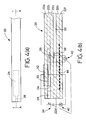
- FIGs. 4(a) and 4(b) there is shown a typical example of a sensing element 20 used in an apparatus according to one embodiment of the present invention, for measuring the oxygen concentration in a combustion exhaust gas containing combustible gas components.
- the sensing element 20 is a plate-like body having a relatively small width and a relatively large length.
- the plate-like body of the sensing element 20 is an integral laminar structure including a plurality of dense, substantially gas-tight layers 22a, 22b, 22c, 22d, 22e and 22f of oxygen ion conductive solid electrolyte.
- These solid electrolyte layers 22a-22f are formed of zirconia ceramics or other known oxygen ion conductive solid electrolyte materials.
- This integral sensing element 20 is produced by co-firing a stack of unfired precursors of the oxygen ion conductive solid electrolyte layers 22a-22f in a manner known in the art.
- the sensing element 20 has a reference gas space in the form of a reference air passage 26 which is formed gas-tightly with respect to the internal cavity 24.
- the reference air passage 26 extends in the longitudinal direction of the sensing element 20, and is open to the ambient atmosphere at one longitudinal end (proximal end) of the sensing element 20.
- the internal cavity 24 is defined by a rectangular hole which is formed through the solid electrolyte layer 22b and which is closed by the adjacent upper and lower solid electrolyte layers 22a, 22c.
- the reference air passage 26 is defined by a rectangular slot which is formed through the solid electrolyte layer 22d and which is closed by the adjacent upper and lower solid electrolyte layers 22c, 22e.
- the solid electrolyte layer 22b has a slot which is closed by the adjacent upper and lower solid electrolyte layers 22a, 22c, so as to provide a diffusion control means in the form of a diffusion control passage 28, which is open at the other longitudinal end (distal end) of the sensing element 20.
- the sensing element 20 is positioned such that the distal end portion at which the diffusion control passage 28 is open is exposed to an external space in which there exists a subject gas (i.e., combustion exhaust gas) including combustible gas components.
- a subject gas i.e., combustion exhaust gas
- the combustible exhaust gas is introduced into the internal cavity 24 through the diffusion control passage 28 under a predetermined diffusion resistance.
- the diffusion control passage 28 functions to limit a rate of flow of the exhaust gas introduced into the internal cavity 24 upon application of a voltage to an electrochemical oxygen pumping cell which will be described, so as to restrict a current flowing through the pumping cell.
- a rectangular porous platinum (Pt) inner pumping electrode 30 is provided in contact with an area of the inner surface of the solid electrolyte layer 22a which is exposed to and partially defines the internal cavity 24. Further, a rectangular porous platinum (Pt) outer pumping electrode 32 is provided in contact with an area of the outer surface of the solid electrolyte layer 22a which correspond to the inner surface area on which the inner pumping electrode 30 is provided.
- These inner and outer pumping electrodes 30, 32 and the solid electrolyte layer 22a constitute an electrochemical oxygen pumping cell.
- the porous platinum (Pt) pumping electrodes 30, 32 are formed of a cermet consisting of platinum (Pt) as an electrode metal and zirconia (ZrO 2 ) as a ceramic material.
- a rectangular porous platinum (Pt) measuring electrode 36 is provided in contact with an area of one of the opposite surfaces of the solid electrolyte layer 22c which is exposed to the internal cavity 24, while a rectangular porous platinum (Pt) reference electrode 38 is provided in contact with the corresponding area of the other surface of the solid electrolyte layer 22c which is exposed to the reference air passage 26.
- These measuring and reference electrodes 36, 38 and the solid electrolyte layer 22c constitute oxygen partial pressure detecting means in the form of an electrochemical sensing cell.
- the sensing cell 22c, 36, 38 is adapted to detect the oxygen partial pressure of the atmosphere in the internal cavity 24 on the basis of an output of a potentiometer 40 indicative of an electromotive force which is induced between the measuring and reference electrodes 36, 38 according to a difference in oxygen concentration between the atmosphere within the internal cavity 24 and the reference air (ambient atmosphere) within the reference air passage 26.
- the voltage of the variable-voltage power source 34 is controlled based on a voltage (referred to as "monitor voltage" where appropriate) which corresponds to the oxygen partial pressure of the atmosphere in the internal cavity 24 detected by the potentiometer 40, so that the oxygen partial pressure in the internal cavity 24 is held at a predetermined value.
- the electric current flowing between the inner and outer pumping electrodes 30, 32 upon application of the controlled voltage supplied from the power source 34 is measured by an ammeter 42. This current is referred to as "pumping current".
- a heater 44 sandwiched by and between the adjacent upper and lower solid electrolyte layers 22e and 22f.
- This heater 44 is energized by a suitable external power source.
- the heater 44 has a resistance (e.g., 9 ⁇ ) determined to maintain the temperature in the internal cavity 24 at 600°C, for instance, when the heater 44 is energized with a nominal or rated voltage of 12V.
- thin electrically insulating layers are formed of alumina or other suitable ceramic material so as to cover the upper and lower surfaces of the heater 44. As shown in Fig.
- the heater 44 has a length sufficient to cover the entire length of the internal cavity 24, so that the space within the internal cavity 24 is uniformly heated to a suitable temperature, to thereby hold the electrochemical oxygen pumping cell (22a, 30, 32) and the electrochemical sensing cell (22c, 36, 38) at substantially the same elevated temperature.
- the thus constructed sensing element 20 is positioned such that the distal end portion at which the diffusion control passage 28 is open is exposed to the combustion exhaust gas space, while the proximal end portion at which the reference air passage 26 is open is exposed to the ambient atmosphere. Accordingly, the combustion exhaust gas containing the combustible gas components is introduced into the internal cavity 24 through the diffusion control passage 28 under the predetermined diffusion resistance.
- the subject gas in the form of the combustion exhaust gas includes combustible gas components such as CO, H 2 and HC, as well as gas components such as N 2 , O 2 , CO 2 and H 2 O.
- the electrochemical oxygen pumping cell 22a, 30, 32 is operated to perform an oxygen pumping action by application of the predetermined voltage between the two pumping electrodes 30, 32, whereby oxygen is pumped out from the internal cavity 24 into the external gas space so that the oxygen concentration in the atmosphere in the internal cavity 24 is controlled to a predetermined level which is low enough to inhibit oxidization and burning or combustion of the combustible gas components within the internal cavity 24.
- the electromotive force induced between the measuring and reference electrodes 36, 38 of the electrochemical oxygen sensing cell is measured by the potentiometer 40, and the voltage (supplied from the variable-voltage power source 34) between the two electrodes 30, 32 of the electrochemical oxygen pumping cell is feed-back controlled to control the measured electromotive force to 800mV at 600°C, for instance.
- the oxygen partial pressure of the atmosphere in the internal cavity 24 is controlled to about 10 -20 atm. At this oxygen partial pressure, oxidization and burning or combustion of the combustible gas components such as HC, CO and H 2 is substantially impossible.
- the voltage to be applied to the electrochemical oxygen pumping cell 22a, 30, 32 is controlled so that the electromotive force which corresponds to a difference between the oxygen concentration in the internal cavity 24 and the oxygen concentration of the reference air corresponds to a desired value of the monitor voltage.
- the oxygen partial pressure (oxygen concentration) within the internal cavity 24 is maintained at a level low enough to inhibit the oxidization and burning or combustion of the combustible gas components in the atmosphere within the internal cavity 24, in the presence of the inner and outer pumping electrodes 30, 32, even under heat due to a relatively high temperature of the combustion exhaust gas which exists in the external gas space and due to the elevated temperature (e.g., 600°C) in the internal space 24 which is heated by the heater 44.
- the oxygen partial pressure in the internal cavity 24 is held at 10 -14 atm or lower, preferably, 10 -16 atm or lower. This state of the internal cavity 24 wherein the oxygen partial pressure is held as described above corresponds to the third range III in the graph of Fig. 3.
- the pumping current flowing between the inner and outer pumping electrodes 30, 32 is detected by the ammeter 42 upon application of the voltage between the two electrodes 30, 32 from the variable-voltage power source 34, such that the voltage corresponds to the monitor voltage that gives the above-indicated state of the internal cavity 24. Since the detected pumping current is proportional to the oxygen concentration in the combustion exhaust gas within the internal cavity 24, and is free from an influence of the combustible gas components, the oxygen concentration in the combustion exhaust gas can be determined or obtained on the basis of the detected pumping current according to a predetermined relationship between the pumping current and the oxygen concentration.
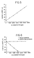
- the graph of Fig. 5 indicates a change of a pumping current Ip between the inner and outer pumping electrodes 30, 32 of the electrochemical oxygen pumping cell, in relation to the O 2 concentration of a standard gas (containing 7% of H 2 O), when the O 2 concentration was changed from 0 to 5000ppm.
- the standard gas included nitrogen (N 2 ) as a carrier gas.
- N 2 nitrogen
- the voltage of the variable-voltage power source 34 is feedback-controlled on the basis of the monitor voltage obtained in the above-described third range III where the O 2 concentration is held at a level low enough to inhibit the oxidization and burning or combustion of the combustible gas components.
- the O 2 concentration in the combustion exhaust gas is obtained based on the detected pumping current flowing through the electrochemical oxygen pumping cell, without the influence of the combustible gas components.
- the graph of Fig. 6 shows interfering characteristics of propane (C 3 H 8 ) as the combustible gas component with respect to the pumping current Ip. Described more specifically, the above-described standard gas in which the O 2 concentration was 2000ppm was used. To this standard gas, C 3 H 8 was added such that the standard gas had different values of C 3 H 8 concentration.
- the graph shows the results of measurement of the pumping current which was obtained by the sensing element 20 of the present invention and by the conventional oxygen sensor, respectively.
- the pumping current was maintained at a constant value in the present sensing element 20 as shown in the graph, without being influenced by the change of the concentration of C 3 H 8 as the combustible gas component.
- the monitor voltage was controlled to 450mV (600°C/450mV) which corresponds to the above-indicated current limiting second range II in the graph of Fig. 3
- the pumping current was considerably influenced by the combustible gas component C 3 H 8 as shown in the graph of Fig. 6, making it impossible to accurately detect the O 2 concentration.
- the measurement of the pumping current according to the conventional oxygen sensor does not assure accurate detection of the O 2 concentration.
- the oxygen ion conductive solid electrolyte body 22 may be formed of a suitable known material other than zirconia ceramics. Further, the solid electrolyte layers 22a-22f and the various electrodes need not be co-fired. For instance, the electrodes may be formed by baking on the appropriate sintered solid electrolyte layers, and the individual solid electrolyte layers some of which carry the electrodes are then bonded together with a suitable glass material.
- the electrodes 30, 32, 36 and 38 are preferably formed of a porous cermet consisting of a mixture of an electrode metal (electrically conductive material) and a ceramic material, for improved adhesion or bonding to the solid electrolyte layers (ceramic substrates). However, these electrodes may consist solely of a metallic material. Of these electrodes, the inner pumping electrode 30 of the electrochemical oxygen pumping cell and the measuring electrode 36 of the electrochemical oxygen sensing cell are preferably formed of a material which has no or only a small degree of function as an oxidizing catalyst. To this end, it is desirable to use Au, Ni or similar electrode material for these electrodes 30, 36.
- the solid electrolyte material e.g., zirconia
- an alloy of such electrode material e.g., Au, Ni
- a noble metal having a relatively high melting point such as Pt, Pd and Rh.
- the function can be made sufficiently small if the alloys include at least 1% of Au, Ni or similar electrode material.
- 1% of Au is added to platinum (Pt), and zirconia (ZrO 2 ) is added to this alloy of the electrode materials such that volume ratio of (Pt and Au) to ZrO 2 is 60:40.
- the functionality as the oxidizing catalyst of the obtained electrode may be sufficiently reduced.
- the electromotive force, i.e., the monitor voltage, detected by the electrochemical oxygen sensing cell is suitably determined depending upon the temperature of the atmosphere within the internal cavity 24 and the selected electrode material, so that the monitor voltage is held within the third range III in the graph of Fig. 3, whereby the O 2 concentration of the atmosphere in the internal cavity 24 is controlled to a level low enough to inhibit the burning or combustion of the combustible gas components in the cavity 24.
- the monitor voltage it is preferable to set the monitor voltage at 600-2000mV, more preferably, 700-1500mV. If the monitor voltage is too low (lower than 600mV), the combustible gas components in the combustion exhaust gas would be oxidized, making it difficult to accurately obtain the O 2 concentration in the cavity 24.
- the monitor voltage is too high (higher than 2000mV)
- the obtained O 2 concentration is affected by decomposition of CO 2 or H 2 O present in the combustion exhaust gas.
- an amount of change of the pumping current with respect to an amount of change of the monitor voltage is relatively large, and the pumping current tends to be influenced by the partial pressures of H 2 O and CO 2 .
- the monitor voltage is determined to be held within the third range III in the graph of Fig.
- the monitor voltage is preferably determined to be a value in an area of the third range III which is relatively near the second range II, where the influence of the partial pressures of H 2 O and CO 2 is comparatively small and the reaction of the combustible gas components with oxygen does not occur.
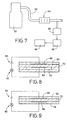
- FIG. 7 there will be explained one example of a system for detecting the deterioration of an exhaust gas control catalyst, which system utilizes the oxygen concentration measuring apparatus constructed as described above.
- the combustion exhaust gas containing the combustible gas components is emitted by an internal combustion engine 50 of an automobile, and discharged outside through an exhaust gas passage 52.
- a catalyst 54 in the form of a known oxidizing catalyst or three way catalyst, which is adapted to oxidize and burn the combustible gas components present in the emitted combustion exhaust gas.
- the catalyst 54 is inspected of its exhaust gas purification efficiency by an oxygen concentration measuring apparatus 56 constructed as shown in Fig. 4, which is disposed at a portion of the exhaust gas passage 52 downstream of the catalyst 54 as viewed in a direction of flow of the combustion exhaust gas from the engine 50.
- the oxygen concentration measuring apparatus 56 is adapted to inspect the combustion exhaust gas which has passed through the catalyst 54, and determine a degree of deterioration of the catalyst on the basis of the amount of oxygen contained in the combustion exhaust gas. If the catalyst 54 is new enough to exhibit a sufficiently high degree of purification efficiency, the oxygen concentration in the combustion exhaust gas which has passed through the catalyst 54 is lowered by an amount corresponding to an amount of oxygen consumed during oxidization and burning or combustion of the combustible gas components. On the other hand, if the catalyst 54 is deteriorated and has a lowered purification efficiency, the amount of oxygen consumed in oxidization and burning of the combustible gas components within the catalyst 54 is small. Thus, the degree of deterioration of the catalyst 54 is determined by measuring the amount of oxygen contained in the exhaust gas which is fed to the oxygen concentration measuring apparatus 56 through the catalyst 54.
- the combustion exhaust gas passes through the catalyst 54 which is provided in the exhaust gas passage 52, and is introduced into the sensing element 20 of the oxygen concentration measuring apparatus 56 constructed as shown in Fig. 4.
- the sensing element 20 detects the pumping current which corresponds to the oxygen concentration in the combustion exhaust gas which has passed through the catalyst 54.
- a determining device 58 determines the degree of deterioration of the catalyst 54, and the result of determination is indicated by a display and warning device 60. Namely, the device 60 indicates the degree of deterioration of the catalyst 54 or informs that the catalyst 54 is no more capable of performing a sufficient catalytic action.
- the pumping current Ip was measured by the oxygen concentration measuring apparatus (56) to inspect the degree of deterioration of the catalyst 54 when the engine (50) was feedback-controlled at the stoichiometric air/fuel ratio.
- the engine (50) used in the test was an in-line 4-cylinder engine having a displacement of 2.0L.
- the catalyst (54) there were prepared five specimens A-E. Namely, the specimen A was brand-new, and the other specimens were subjected to aging treatment such that aging times during which the aging treatment was effected on the specimens B, C, D, E increase in the order of description.
- Each of the thus prepared specimen catalysts A-E was installed in the exhaust gas passage of the engine, and the pumping current Ip was measured to obtain the oxygen concentration in the exhaust combustion gas which has passed through each of the specimens A-E, so as to inspect the degree of deterioration of each specimen.
- the degree of deterioration of the catalyst is determined on the basis of the detected pumping current Ip. For instance, it is determined that the conversion efficiency of the catalyst is lower than a predetermined level when the detected pumping current IP is higher than a predetermined value.
- the internal cavity 24 is held in communication with the external gas space through the diffusion control passage 28.
- the internal cavity 24 may directly communicate with the external gas space at the distal end of the sensing element 20. That is, the diffusion control passage 28 may have the same width dimension as the internal cavity 24.
- the cross sectional area of the diffusion control passage 28 be smaller than that of the internal cavity 24.
- the diffusion control passage 28 as the diffusion control means in the illustrated embodiment may be replaced with a porous layer 62 as shown in Fig. 8, through which the combustion exhaust gas is introduced into the sensing element 20 under a predetermined diffusion resistance.
- the monitor voltage measured in the electrochemical oxygen sensing cell is detected to feedback-control the voltage of the variable-voltage power source 34 to be applied between the two pumping electrodes 30, 32 of the electrochemical oxygen pumping cell.
- the detection of the monitor voltage may be eliminated.
- a predetermined constant voltage is applied from a constant-voltage power source 64 between pumping electrodes 66, 68 of the electrochemical oxygen pumping cell, so that oxygen in the combustion exhaust gas which is present around the pumping electrode 66 is pumped into an atmosphere communication passage 70.
- the pumping current between the two electrode 66, 68 is measured by the ammeter 42 to obtain the concentration of the oxygen in the atmosphere communication passage 70.
- the reference numeral 72 indicates a solid electrolyte body.
- the pumping electrode 68 through which oxygen is pumped out may be covered by a porous body 74, so that oxygen pumped out by the electrochemical pumping cell is retained around the pumping electrode 68 and utilized as reference oxygen.
- the electromotive force induced between the two electrodes 66, 68 is superimposed, whereby the voltage supplied from the constant-voltage power source 64 can be lowered.
- the sensing element 20 may be constructed with various other modifications which may occur to those skilled in the art.
- the configuration of the sensing element 20 is by no means limited to the plate-like body of the illustrated embodiment, but may be a cylindrical body.
- the reference electrode 38 and the outer pumping electrode 32 which are disposed in the reference air passage 26 may be constructed as a common electrode.
- the concentration of oxygen remaining in the combustion exhaust gas can be accurately obtained without being influenced by the combustible gas components contained in the combustion exhaust gas. Further, it is possible to properly determine the degree of deterioration of the catalyst on the basis of the obtained oxygen concentration.
- the present method is effectively utilized in an apparatus and method for accurately measuring the concentration of oxygen in the combustion exhaust gas which contains the combustible gas components.
Applications Claiming Priority (3)
| Application Number | Priority Date | Filing Date | Title |
|---|---|---|---|
| JP9361295 | 1995-04-19 | ||
| JP09361295A JP3481344B2 (ja) | 1995-04-19 | 1995-04-19 | 排ガス浄化用触媒の劣化検知方法及びそのためのシステム |
| JP93612/95 | 1995-04-19 |
Publications (3)
| Publication Number | Publication Date |
|---|---|
| EP0743431A2 true EP0743431A2 (de) | 1996-11-20 |
| EP0743431A3 EP0743431A3 (de) | 1997-08-13 |
| EP0743431B1 EP0743431B1 (de) | 2001-07-11 |
Family
ID=14087160
Family Applications (1)
| Application Number | Title | Priority Date | Filing Date |
|---|---|---|---|
| EP96302665A Expired - Lifetime EP0743431B1 (de) | 1995-04-19 | 1996-04-17 | Verfahren und Vorrichtung zum Feststellen der Verschlechterung eines Abgaskatalysators |
Country Status (4)
| Country | Link |
|---|---|
| US (1) | US5772965A (de) |
| EP (1) | EP0743431B1 (de) |
| JP (1) | JP3481344B2 (de) |
| DE (1) | DE69613757T2 (de) |
Cited By (6)
| Publication number | Priority date | Publication date | Assignee | Title |
|---|---|---|---|---|
| WO1997016631A2 (de) * | 1995-10-31 | 1997-05-09 | Siemens Aktiengesellschaft | Verfahren zur überprüfung der funktionsfähigkeit eines katalysators mit einem sauerstoffsensor |
| EP0797094A2 (de) * | 1996-03-19 | 1997-09-24 | NGK Spark Plug Co. Ltd. | Abgassensor |
| EP0848250A2 (de) * | 1996-12-10 | 1998-06-17 | Ngk Insulators, Ltd. | Gassensor und Verfahren zur Diagnose einer Fehlfunktion eines Abgasreinigungsgeräts |
| EP1004877A2 (de) * | 1998-11-25 | 2000-05-31 | Ngk Spark Plug Co., Ltd | Gassensor, Methode zu dessen Herstellung und System unter Verwendung dieses Gassensors |
| WO2013167443A1 (de) * | 2012-05-09 | 2013-11-14 | Continental Automotive Gmbh | Sensorelement mit cermet grundschicht und platin deckschicht |
| CN110308190A (zh) * | 2019-07-30 | 2019-10-08 | 苏州禾苏传感器科技有限公司 | 一种带扩散障片式氧传感器芯片 |
Families Citing this family (8)
| Publication number | Priority date | Publication date | Assignee | Title |
|---|---|---|---|---|
| JP3544437B2 (ja) * | 1996-09-19 | 2004-07-21 | 日本碍子株式会社 | ガスセンサ |
| JP3672681B2 (ja) * | 1996-09-30 | 2005-07-20 | 株式会社日本自動車部品総合研究所 | ガスセンサ |
| JP3332761B2 (ja) * | 1996-11-08 | 2002-10-07 | 日本特殊陶業株式会社 | 酸素濃度・窒素酸化物濃度測定方法及び装置 |
| JP3876506B2 (ja) * | 1997-06-20 | 2007-01-31 | 株式会社デンソー | ガス濃度の測定方法及び複合ガスセンサ |
| EP0916941B1 (de) * | 1997-10-14 | 2003-06-04 | NGK Spark Plug Co. Ltd. | Verfahren und Vorrichtung zur Bestimmung des Betriebszustands eines NOx Okklusionskatalysators |
| JP4739716B2 (ja) * | 2003-09-29 | 2011-08-03 | ローベルト ボツシユ ゲゼルシヤフト ミツト ベシユレンクテル ハフツング | センサ素子 |
| JP2006153598A (ja) * | 2004-11-26 | 2006-06-15 | Honda Motor Co Ltd | ガス検出装置およびガス検出素子の制御方法 |
| JP6511282B2 (ja) * | 2015-02-10 | 2019-05-15 | エナジーサポート株式会社 | 酸素濃度測定装置及び酸素濃度測定方法 |
Citations (6)
| Publication number | Priority date | Publication date | Assignee | Title |
|---|---|---|---|---|
| DE2304464A1 (de) * | 1973-01-31 | 1974-08-08 | Bosch Gmbh Robert | Messfuehler fuer die ueberwachung der funktionsfaehigkeit von katalysatoren in abgasentgiftungsanlagen von brennkraftmaschinen |
| US4776943A (en) * | 1984-02-20 | 1988-10-11 | Nissan Motor Co., Ltd. | Device for detecting air-fuel ratio of mixture over wide range from below to above stoichiometric ratio |
| JPH04369471A (ja) * | 1991-06-14 | 1992-12-22 | Honda Motor Co Ltd | 酸素濃度検出装置 |
| US5250169A (en) * | 1991-06-07 | 1993-10-05 | Ford Motor Company | Apparatus for sensing hydrocarbons and carbon monoxide |
| WO1994015206A1 (de) * | 1992-12-23 | 1994-07-07 | Robert Bosch Gmbh | Sensor zur bestimmung von gaskomponenten und/oder von gaskonzentrationen von gasgemischen |
| DE4408504A1 (de) * | 1994-03-14 | 1995-09-21 | Bosch Gmbh Robert | Sensor zur Bestimmung der Konzentration von Gaskomponenten in Gasgemischen |
Family Cites Families (7)
| Publication number | Priority date | Publication date | Assignee | Title |
|---|---|---|---|---|
| US4579643A (en) * | 1983-11-18 | 1986-04-01 | Ngk Insulators, Ltd. | Electrochemical device |
| DE3482745D1 (de) * | 1983-11-18 | 1990-08-23 | Ngk Insulators Ltd | Elektrochemische vorrichtung mit einem messfuehlelement. |
| DE3686622T2 (de) * | 1985-09-11 | 1993-04-01 | British Tech Group | Verwendung von dioxopiperidin-derivaten zur behandlung von anxietas, zur herabsetzung von chronischen abnormal hohen gehirn-spiegeln serotonins oder 5-hydroxy-indolessigsaeure und zur behandlung von bakteriellen oder viralen infektionen. |
| US5145566A (en) * | 1988-09-30 | 1992-09-08 | Ford Motor Company | Method for determining relative amount of oxygen containing gas in a gas mixture |
| DE4007856A1 (de) * | 1990-03-13 | 1991-09-19 | Bosch Gmbh Robert | Sensorelement fuer eine sauerstoffgrenzstromsonde zur bestimmung des (lambda)-wertes von gasgemischen |
| JP2880273B2 (ja) * | 1990-08-20 | 1999-04-05 | 株式会社日本自動車部品総合研究所 | 酸素濃度検出装置 |
| US5281313A (en) * | 1993-03-18 | 1994-01-25 | Ford Motor Company | Selective combustible sensor and method |
-
1995
- 1995-04-19 JP JP09361295A patent/JP3481344B2/ja not_active Expired - Fee Related
-
1996
- 1996-04-15 US US08/632,148 patent/US5772965A/en not_active Expired - Lifetime
- 1996-04-17 DE DE69613757T patent/DE69613757T2/de not_active Expired - Lifetime
- 1996-04-17 EP EP96302665A patent/EP0743431B1/de not_active Expired - Lifetime
Patent Citations (6)
| Publication number | Priority date | Publication date | Assignee | Title |
|---|---|---|---|---|
| DE2304464A1 (de) * | 1973-01-31 | 1974-08-08 | Bosch Gmbh Robert | Messfuehler fuer die ueberwachung der funktionsfaehigkeit von katalysatoren in abgasentgiftungsanlagen von brennkraftmaschinen |
| US4776943A (en) * | 1984-02-20 | 1988-10-11 | Nissan Motor Co., Ltd. | Device for detecting air-fuel ratio of mixture over wide range from below to above stoichiometric ratio |
| US5250169A (en) * | 1991-06-07 | 1993-10-05 | Ford Motor Company | Apparatus for sensing hydrocarbons and carbon monoxide |
| JPH04369471A (ja) * | 1991-06-14 | 1992-12-22 | Honda Motor Co Ltd | 酸素濃度検出装置 |
| WO1994015206A1 (de) * | 1992-12-23 | 1994-07-07 | Robert Bosch Gmbh | Sensor zur bestimmung von gaskomponenten und/oder von gaskonzentrationen von gasgemischen |
| DE4408504A1 (de) * | 1994-03-14 | 1995-09-21 | Bosch Gmbh Robert | Sensor zur Bestimmung der Konzentration von Gaskomponenten in Gasgemischen |
Non-Patent Citations (1)
| Title |
|---|
| PATENT ABSTRACTS OF JAPAN vol. 017, no. 250 (P-1537), 18 May 1993 & JP 04 369471 A (HONDA MOTOR CO LTD), 22 December 1992, * |
Cited By (12)
| Publication number | Priority date | Publication date | Assignee | Title |
|---|---|---|---|---|
| WO1997016631A2 (de) * | 1995-10-31 | 1997-05-09 | Siemens Aktiengesellschaft | Verfahren zur überprüfung der funktionsfähigkeit eines katalysators mit einem sauerstoffsensor |
| WO1997016631A3 (de) * | 1995-10-31 | 1997-07-24 | Siemens Ag | Verfahren zur überprüfung der funktionsfähigkeit eines katalysators mit einem sauerstoffsensor |
| US5974787A (en) * | 1995-10-31 | 1999-11-02 | Siemens Aktiengesellschaft | Method for testing the functional capability of a catalytic converter with an oxygen sensor |
| EP0797094A2 (de) * | 1996-03-19 | 1997-09-24 | NGK Spark Plug Co. Ltd. | Abgassensor |
| EP0797094A3 (de) * | 1996-03-19 | 2000-04-05 | NGK Spark Plug Co. Ltd. | Abgassensor |
| EP0848250A2 (de) * | 1996-12-10 | 1998-06-17 | Ngk Insulators, Ltd. | Gassensor und Verfahren zur Diagnose einer Fehlfunktion eines Abgasreinigungsgeräts |
| EP0848250A3 (de) * | 1996-12-10 | 2000-05-03 | Ngk Insulators, Ltd. | Gassensor und Verfahren zur Diagnose einer Fehlfunktion eines Abgasreinigungsgeräts |
| EP1004877A2 (de) * | 1998-11-25 | 2000-05-31 | Ngk Spark Plug Co., Ltd | Gassensor, Methode zu dessen Herstellung und System unter Verwendung dieses Gassensors |
| EP1004877A3 (de) * | 1998-11-25 | 2002-01-23 | Ngk Spark Plug Co., Ltd | Gassensor, Methode zu dessen Herstellung und System unter Verwendung dieses Gassensors |
| WO2013167443A1 (de) * | 2012-05-09 | 2013-11-14 | Continental Automotive Gmbh | Sensorelement mit cermet grundschicht und platin deckschicht |
| CN104285141A (zh) * | 2012-05-09 | 2015-01-14 | 大陆汽车有限责任公司 | 带有金属陶瓷基层和铂覆盖层的传感元件 |
| CN110308190A (zh) * | 2019-07-30 | 2019-10-08 | 苏州禾苏传感器科技有限公司 | 一种带扩散障片式氧传感器芯片 |
Also Published As
| Publication number | Publication date |
|---|---|
| EP0743431A3 (de) | 1997-08-13 |
| EP0743431B1 (de) | 2001-07-11 |
| US5772965A (en) | 1998-06-30 |
| DE69613757T2 (de) | 2002-05-08 |
| DE69613757D1 (de) | 2001-08-16 |
| JPH08285809A (ja) | 1996-11-01 |
| JP3481344B2 (ja) | 2003-12-22 |
Similar Documents
| Publication | Publication Date | Title |
|---|---|---|
| EP1001262B1 (de) | Verfahren zum Messen einer Gaskomponente | |
| EP0731351B1 (de) | Verfahren und Vorrichtung zur Messung einer brennbaren Gaskomponente durch Verbrennung der Komponente | |
| US5672811A (en) | Method of measuring a gas component and sensing device for measuring the gas component | |
| US4927517A (en) | NOx sensor having catalyst for decomposing NOx | |
| EP0769693B1 (de) | Verfahren un Vorrichtung zum Messen von einem vorbestimmten Gaskomponenten eines Messgases | |
| EP1074834B1 (de) | Verfahren und Vorrichtung zur Messung der Stickstoffoxidkonzentration | |
| EP0257842B1 (de) | Elektrochemischer NOx-Sensor | |
| EP0743431B1 (de) | Verfahren und Vorrichtung zum Feststellen der Verschlechterung eines Abgaskatalysators | |
| US6344134B1 (en) | Method for measuring NOx concentration and NOx concentration sensor | |
| EP0769694A1 (de) | NOx-Sensor und Messverfahren dazu | |
| US5985118A (en) | Solid electrolyte gas concentration detector | |
| EP1004877B1 (de) | Gassensor, Methode zu dessen Herstellung und System unter Verwendung dieses Gassensors | |
| JP3664558B2 (ja) | ガスセンサ | |
| JP3619344B2 (ja) | 窒素酸化物の測定装置 | |
| US6346178B1 (en) | Simplified wide range air fuel ratio sensor | |
| JP3511468B2 (ja) | 被測定ガス中のNOx濃度の測定方法 | |
| US20050235631A1 (en) | Sensor element for a sensor for determining the oxygen concentration in the exhaust gas of internal combustion engines | |
| JP3756123B2 (ja) | NOxセンサ並びにNOx濃度の測定方法 |
Legal Events
| Date | Code | Title | Description |
|---|---|---|---|
| PUAI | Public reference made under article 153(3) epc to a published international application that has entered the european phase |
Free format text: ORIGINAL CODE: 0009012 |
|
| 17P | Request for examination filed |
Effective date: 19960503 |
|
| AK | Designated contracting states |
Kind code of ref document: A2 Designated state(s): DE FR GB IT SE |
|
| PUAL | Search report despatched |
Free format text: ORIGINAL CODE: 0009013 |
|
| AK | Designated contracting states |
Kind code of ref document: A3 Designated state(s): DE FR GB IT SE |
|
| GRAG | Despatch of communication of intention to grant |
Free format text: ORIGINAL CODE: EPIDOS AGRA |
|
| 17Q | First examination report despatched |
Effective date: 20001012 |
|
| GRAG | Despatch of communication of intention to grant |
Free format text: ORIGINAL CODE: EPIDOS AGRA |
|
| GRAH | Despatch of communication of intention to grant a patent |
Free format text: ORIGINAL CODE: EPIDOS IGRA |
|
| GRAH | Despatch of communication of intention to grant a patent |
Free format text: ORIGINAL CODE: EPIDOS IGRA |
|
| GRAA | (expected) grant |
Free format text: ORIGINAL CODE: 0009210 |
|
| AK | Designated contracting states |
Kind code of ref document: B1 Designated state(s): DE FR GB IT SE |
|
| REF | Corresponds to: |
Ref document number: 69613757 Country of ref document: DE Date of ref document: 20010816 |
|
| ET | Fr: translation filed | ||
| REG | Reference to a national code |
Ref country code: GB Ref legal event code: IF02 |
|
| PLBE | No opposition filed within time limit |
Free format text: ORIGINAL CODE: 0009261 |
|
| STAA | Information on the status of an ep patent application or granted ep patent |
Free format text: STATUS: NO OPPOSITION FILED WITHIN TIME LIMIT |
|
| 26N | No opposition filed | ||
| PGFP | Annual fee paid to national office [announced via postgrant information from national office to epo] |
Ref country code: SE Payment date: 20040507 Year of fee payment: 9 |
|
| PG25 | Lapsed in a contracting state [announced via postgrant information from national office to epo] |
Ref country code: IT Free format text: LAPSE BECAUSE OF NON-PAYMENT OF DUE FEES Effective date: 20050417 |
|
| PG25 | Lapsed in a contracting state [announced via postgrant information from national office to epo] |
Ref country code: SE Free format text: LAPSE BECAUSE OF NON-PAYMENT OF DUE FEES Effective date: 20050418 |
|
| EUG | Se: european patent has lapsed | ||
| PGFP | Annual fee paid to national office [announced via postgrant information from national office to epo] |
Ref country code: GB Payment date: 20100312 Year of fee payment: 15 |
|
| PGFP | Annual fee paid to national office [announced via postgrant information from national office to epo] |
Ref country code: FR Payment date: 20100420 Year of fee payment: 15 |
|
| PGFP | Annual fee paid to national office [announced via postgrant information from national office to epo] |
Ref country code: DE Payment date: 20100430 Year of fee payment: 15 |
|
| REG | Reference to a national code |
Ref country code: DE Ref legal event code: R119 Ref document number: 69613757 Country of ref document: DE |
|
| REG | Reference to a national code |
Ref country code: DE Ref legal event code: R119 Ref document number: 69613757 Country of ref document: DE |
|
| GBPC | Gb: european patent ceased through non-payment of renewal fee |
Effective date: 20110417 |
|
| REG | Reference to a national code |
Ref country code: FR Ref legal event code: ST Effective date: 20111230 |
|
| PG25 | Lapsed in a contracting state [announced via postgrant information from national office to epo] |
Ref country code: FR Free format text: LAPSE BECAUSE OF NON-PAYMENT OF DUE FEES Effective date: 20110502 |
|
| PG25 | Lapsed in a contracting state [announced via postgrant information from national office to epo] |
Ref country code: GB Free format text: LAPSE BECAUSE OF NON-PAYMENT OF DUE FEES Effective date: 20110417 |
|
| PG25 | Lapsed in a contracting state [announced via postgrant information from national office to epo] |
Ref country code: DE Free format text: LAPSE BECAUSE OF NON-PAYMENT OF DUE FEES Effective date: 20111031 |