EP0794532A1 - Kassette mit herausnehmbarer platte - Google Patents
Kassette mit herausnehmbarer platte Download PDFInfo
- Publication number
- EP0794532A1 EP0794532A1 EP96930385A EP96930385A EP0794532A1 EP 0794532 A1 EP0794532 A1 EP 0794532A1 EP 96930385 A EP96930385 A EP 96930385A EP 96930385 A EP96930385 A EP 96930385A EP 0794532 A1 EP0794532 A1 EP 0794532A1
- Authority
- EP
- European Patent Office
- Prior art keywords
- disk
- main body
- lid
- case main
- taking out
- Prior art date
- Legal status (The legal status is an assumption and is not a legal conclusion. Google has not performed a legal analysis and makes no representation as to the accuracy of the status listed.)
- Granted
Links
- 230000009471 action Effects 0.000 claims description 9
- 230000035515 penetration Effects 0.000 claims description 9
- GOLXNESZZPUPJE-UHFFFAOYSA-N spiromesifen Chemical compound CC1=CC(C)=CC(C)=C1C(C(O1)=O)=C(OC(=O)CC(C)(C)C)C11CCCC1 GOLXNESZZPUPJE-UHFFFAOYSA-N 0.000 claims description 8
- 230000005484 gravity Effects 0.000 claims description 7
- 230000004308 accommodation Effects 0.000 claims description 3
- 230000005489 elastic deformation Effects 0.000 claims description 3
- 230000008859 change Effects 0.000 abstract description 3
- 238000001514 detection method Methods 0.000 description 27
- 239000011347 resin Substances 0.000 description 26
- 229920005989 resin Polymers 0.000 description 26
- 230000003287 optical effect Effects 0.000 description 22
- 238000000034 method Methods 0.000 description 5
- 238000007599 discharging Methods 0.000 description 2
- 230000001965 increasing effect Effects 0.000 description 2
- 230000002441 reversible effect Effects 0.000 description 2
- 229930182556 Polyacetal Natural products 0.000 description 1
- 239000000470 constituent Substances 0.000 description 1
- 238000011109 contamination Methods 0.000 description 1
- 230000008878 coupling Effects 0.000 description 1
- 238000010168 coupling process Methods 0.000 description 1
- 238000005859 coupling reaction Methods 0.000 description 1
- 238000010586 diagram Methods 0.000 description 1
- 239000000428 dust Substances 0.000 description 1
- 230000000694 effects Effects 0.000 description 1
- 230000002708 enhancing effect Effects 0.000 description 1
- 230000004927 fusion Effects 0.000 description 1
- 230000007246 mechanism Effects 0.000 description 1
- 239000004033 plastic Substances 0.000 description 1
- 239000004417 polycarbonate Substances 0.000 description 1
- 229920000515 polycarbonate Polymers 0.000 description 1
- 229920006324 polyoxymethylene Polymers 0.000 description 1
- 238000000275 quality assurance Methods 0.000 description 1
- 230000002269 spontaneous effect Effects 0.000 description 1
Images


Classifications
-
- G—PHYSICS
- G11—INFORMATION STORAGE
- G11B—INFORMATION STORAGE BASED ON RELATIVE MOVEMENT BETWEEN RECORD CARRIER AND TRANSDUCER
- G11B23/00—Record carriers not specific to the method of recording or reproducing; Accessories, e.g. containers, specially adapted for co-operation with the recording or reproducing apparatus ; Intermediate mediums; Apparatus or processes specially adapted for their manufacture
- G11B23/02—Containers; Storing means both adapted to cooperate with the recording or reproducing means
- G11B23/03—Containers for flat record carriers
- G11B23/0301—Details
- G11B23/0302—Auxiliary features
- G11B23/0303—Write protect features with a sliding part
-
- G—PHYSICS
- G11—INFORMATION STORAGE
- G11B—INFORMATION STORAGE BASED ON RELATIVE MOVEMENT BETWEEN RECORD CARRIER AND TRANSDUCER
- G11B23/00—Record carriers not specific to the method of recording or reproducing; Accessories, e.g. containers, specially adapted for co-operation with the recording or reproducing apparatus ; Intermediate mediums; Apparatus or processes specially adapted for their manufacture
- G11B23/02—Containers; Storing means both adapted to cooperate with the recording or reproducing means
- G11B23/03—Containers for flat record carriers
- G11B23/0301—Details
- G11B23/0317—Containers with interchangeable record carriers
Definitions
- the present invention relates to a disk cartridge used in an optical disk information memory device such as data file device and image file device, and the disk cartridge capable of taking out an optical disk which can take out, for example, a recording optical disk.
- Optical disks may be classified into read-only optical disks such as CD and CD-ROM, and recording optical disks. Most read-only optical disks are sold as bare disks without cartridge. On the other hand, recording optical disks are sold in cartridge to prevent deposit of dust or fingerprint on the disk surface. This recording optical disk contained in the cartridge cannot be taken out of the cartridge structurally.
- the optical disk devices are available in reproducing only devices for loading bare disks only, and recording and reproducing devices for loading the cartridge type only. And recently, there is an increasing demand of reproducing the read-only bare disk in the recording and reproducing device capable of loading only the cartridge type, or reproducing the recording optical disk contained in the cartridge in the reproducing only machine for bare disks.
- a bare disk is put in a cartridge capable of taking out a cartridge in the same shape and dimensions as the recording cartridge to change into a cartridge type, so that it can be reproduced in the recording and reproducing device.
- a cartridge capable of taking out the disk to enable this method is disclosed in Japanese Laid-open Utility Model 1-159274, which is further described later
- the following method may be considered. That is, in the disk cartridge capable of taking out the disk as explained as the means for realizing the former request, the optical disk for recording is accommodated, and it is loaded into the recording and reproducing device to record desired data into the recording optical disk. This recording optical disk is once taken out of the cartridge, and reproduced by the reproducing only device.
- a disk 101 is a read-only optical disk such as CD-ROM.
- a case main body 102 is for accommodating the disk 101, and is composed by coupling upper and lower halves of same shape.
- Fig. 17 shows the state of the disk 101 being accommodated in the case main body 102. In the diagram, only the lower half 103 is shown, and the upper half is not visible because it is at the back side of the lower half 103.
- a disk access 104 for allowing to pass the disk 101 is provided at the back side. Inside the case main body 102, a guide passage leading from the initial accommodating position of the disk 101 up to the disk access 104 is formed straightly.
- This guide passage is formed along lateral walls 105a, 105b, and is a wide passage slightly wider than the diameter of the disk 101.
- Reference numeral 106 is a lid for opening and closing the disk access 104, and its one end is rotatably supported in a rotary concave part 107 near the disk access 104 of the case main body 102. At the other end of the lid 106, a flexible deforming hook 108 provided near the lateral wall 105a of the case main body 102 is stopped, and an elastic clasp 109 for fixing and holding the lid 106 on the case main body 102 is formed.
- Reference numeral 110 is a handle attached to the lid 106, and it is engaged with a notch 111 in the case main body 102.
- Reference numeral 112 is a shutter composed of two pieces for opening and closing the opening, and its leading end is guided and held by a shutter holder plate 113 fixed on the lower half.
- the plastic clasp 109 or hook 108 is elastically deformed in a direction of disengaging the elastic clasp 109 and hook 108, and the lid 106 rotates about the rotary concave part 107.
- the cartridge is inclined, and the disk 101 is allowed to slide by gravity in the case main body 102 to be discharged from the disk access 104.
- the discharged disk 101 is received, and the disk 101 is picked by fingers, and the disk 101 is drawn out from the disk access 104, thereby finishing the action of taking out the disk.
- the read-only optical disk can be reproduced in the recording and reproducing device capable of loading only the cartridge type.
- the disk information side may be touched by finger.
- the read-only optical disk such as CD-ROM
- fingerprint is deposited on the information side of the disk, but in the case of optical disk for recording, if fingerprint is left over on the information side of the disk, possibility of recording failure is high.
- the cartridge capable of taking out the disk in the above constitution is directly used as the cartridge for handling an optical disk for recording, fingerprint is likely to be formed on the optical disk as mentioned above, and recording failure is likely to occur when recorded by putting the optical disk for recording back into the cartridge.
- the width of the cartridge must be wider than the diameter of the disk 101 by the portion of the occupied area of the lid 106 near the rotary concave part 107, and dead space is formed in the cartridge, and the efficiency is poor.
- the width of the conventional cartridge not capable of taking out the disk is close to the diameter of the disk, it is difficult to set the width of the cartridge capable of taking out the disk equal to the width of the conventional cartridge not capable of taking out the disk, and it is hard to realize compatibility of both shapes.
- the invention is a disk cartridge capable of taking out a disk which comprises:
- the invention is a disk cartridge capable of taking out a disk, wherein the move suppressing/stopping means possesses an abutting part at a position of suppressing or stopping the straight move of the disk in the direction determined by a guide portion extended from a disk accommodation initial position of the disk accommodating part toward the disk access.
- the invention is a disk cartridge capable of taking out a disk, wherein the abutting portion is provided in at least one position so as to abut against an outer circumferential end of the disk substantially from one side when the disk is taken outside, and there is no abutting portion except for this abutting portion of the outer circumferential end when the outer circumferential end abuts against the abutting part.
- the invention is a disk cartridge capable of taking out a disk, wherein the abutting part is provided in at least two positions so as to abut against the outer circumferential end of the disk substantially from both sides at the same time when the disk is taken outside, and one or both of the abutting parts can be deformed elastically.
- the invention is a disk cartridge capable of taking out a disk, wherein the lid is supported so as to be rotatable in a specified range at an end of the case main body, and the abutting part is provided at specified position of the lid, and the abutting part is provided so that the outer circumferential end of the disk once abuts against the abutting part and then the moving speed of the disk is lowered than before abutting when the lid is opened and the disk has move the specified distance in the direction determined by the guide portion by gravity.
- the invention is a disk cartridge capable of taking out a disk, wherein the lid is supported so as to be rotatable in a specified range at an end of the case main body, and one of the two abutting parts is provided at a specified position of the lid, and the other is provided near the disk access of the case main body, and one or both of the abutting parts are deformed elastically, when the lid is opened and the disk has move the specified distance in the direction determined by the guide portion by gravity, so that the outer circumferential end of the disk abuts against the both abutting parts simultaneously, and then the disk moves more slowly than before abutting or stops temporarily.
- the invention is a disk cartridge capable of taking out a disk, wherein the lid possesses a lock member to be fixed to the case main body with the disk access closed, and the abutting part provided in the lid is deformed elastically by abutting against the case main body with the lid closed, and the abutting part maintains the thrusting force for rotating the lid in the opening direction when the locked state of the case main body and the lock member is cleared, by the elastic deformation in the closed lid state.
- the invention is a disk cartridge capable of taking out a disk, wherein the disk access is formed from one end surface to other end surface adjacent to this end surface, out of substantially four end surfaces of the case main body.
- the invention is a disk cartridge capable of taking out a disk, wherein the disk has a central hole, and the abutting part is constituted so that the central hole of the disk may be exposed outside from the case main body when the disk at the position of abutting against the abutting part.
- the invention is a disk cartridge capable of taking out a disk, wherein the case main body has a concave part at a position of exposing the central hole of the disk to outside from the case main body when the disk at the position of abutting against the abutting part, and the lid has a handle for closing the concave part when the disk access of the case main body is closed.
- the invention is a disk cartridge capable of taking out a disk, wherein a concave part or a penetration hole is formed in one of the case main body and lid, and a convex part to be fitted into the concave part or penetration hole is formed in the other, so that the lid may be fitted and fixed into the case main body, with the disk access of the case main body closed by the lid, and the convex part is formed integrally on the case main body or the lid so as to be removed from outside.
- the invention is a disk cartridge capable of taking out a disk, wherein it is possible to judge whether the disk is once removed outside from the case main body by the presence or absence of the convex part.
- the invention is a disk cartridge capable of taking out a disk, wherein the case main body has openings at both sides, the convex parts are formed on both sides of the lid, and detecting means provided in an external device for detecting presence or absence of the convex parts can detect one of the two convex parts when the disk cartridge is loaded in the external device by its surface side or back side.
- the invention is a disk cartridge capable of taking out a disk, wherein the convex part is formed integrally on the lid, and the lid and the case main body are different in color.
- the invention is a disk cartridge capable of taking out a disk, wherein the disk is a disk for recording, and write-inhibit means for preventing accidental erasure of recorded data on the disk at the time of recording action into the disk is provided at least in the lid.
- the invention is a disk cartridge capable of taking out a disk, wherein the write-inhibit means possesses a movable protrusion formed integrally on the lid, and a write-inhibit hole corresponding to a movable range of the protrusion formed on the case main body, and the protrusion is held at predetermined position showing record forbid or record enable state, depending on the convex or concave part provided at the inner side of the write-inhibit hole.
- the invention is a disk cartridge capable of taking out a disk, wherein the case main body is composed of plate members of upper half and lower half, and a gripping member for engaging with the upper and lower halves when the lid closes the disk access of the case main body to prevent lifting of the upper and lower halves is formed in the lid.
- the invention is a disk cartridge capable of taking out a disk, wherein the gripping member can be deformed elastically, and has a stopping pawl at its free end, and the upper and lower halves have a concave part to be engaged with the stopping pawl, and the gripping member, when inserted into the upper and lower halves and fitted and fixed, is engaged with the concave part of the upper and lower halves after the stopping pawl abuts and moves on the upper and lower halves.
- the disk moves a specific range along the inner surface of the side wallof the case main body, then abuts against, for example, the abutting member and the moving speed of the disk drops, and the disk discharged outside through the disk access can be held easily by hand, so that controllability in disk discharge may be enhanced.
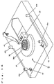
- Fig. 1 is a perspective exploded view of a cartridge capable of taking out a disk of the embodiment
- Fig. 2 is an appearance view of detached state of lid of the cartridge
- Fig. 3 is an appearance view of the lid of the cartridge
- Fig. 4 is a sectional magnified perspective view of a stopping bar of the cartridge
- Fig. 5 is a perspective appearance view of the cartridge.
- reference numeral 1 is a disk of 120 mm in diameter having a central hole 1a
- reference numeral 2 is a case main body of 124 mm in width for accommodating the disk 1, being composed of identical upper half 3 and lower half 4 coupled together.
- the disk 1 is an optical disk for recording.
- the upper half 3 and lower half 4 are formed of polycarbonate, ABS, or other resin, and are coupled by fusion.
- Reference numeral 5 is a disk access allowing to pass through the disk 1 formed along two side walls 6a, 6b of the case main body 2.
- the disk access 5 composed of an opening 5a extending over the side wall 6a, and an opening 5b formed in part of the side wall 6b.
- the side wall 6a and side wall 6b correspond respectively to one end face of substantially four end faces of the case main body 2 of the invention, and other end face adjacent to this end face.
- Reference numeral 7 is a U-shaped inner wall formed inside of the upper half 3 and lower half 5.
- An arc portion 7a of the inner wall 7 is an accommodation wall of a disk accommodating unit 8 for accommodating the disk 1 in the case main body 2, together with an arc portion 21 of a lid described later.
- Straight portions 7b, 7c of the inner wall 7 communicate with the disk access 5, and serve as guides for leading the disk into the disk access 5.
- an opening 9 for inserting a pickup and a disk motor, positioning holes 10a, 10b to be engaged with pins of the disk device for placing the cartridge in a specified position, and oblong write-inhibit holes 11a, 11b for preventing accidental erasure of recorded data.
- the write-inhibit hole 11a is opened to the side wall 6a, and the write-inhibit hole 11a of the upper half 3 confronts the write-inhibit hole 11b of the lower half 4.
- a semicircular notch 12 is provided near the middle of the side wall 6a side of the upper half 3 and lower half 4.
- the concave part of the invention corresponds to the notch 12.
- Reference numeral 13 is a slider slidably held inside of the case main body 2, and a shutter 14 with a U section having a shielding part 14a for opening and closing the opening 9 is coupled.
- the leading end of the shielding part 14a of the shutter 14 is guided and held in a shutter holder 15 fixed in the upper half 3 and lower half 4 (see Fig. 2).
- the slider 13 has an opener concave part 13a to be engaged with a shutter opening 41 (see Fig. 14) of the disk device side described later.
- Reference numeral 16 is a torsion spring disposed in the case main body 2, with one end fixed in the corner of the case main body 2 and other end in the slider 13, and it thrusts the shutter 14 in a direction for closing the opening 9.
- Reference numeral 17 is a lid for opening and closing the disk access 5, and is rotatably supported with a pivot 17a inserted in a rotary concave part 18 provided in the corner of the case main body 2.
- the lid 17 is a resin formed piece of polyacetal, and is composed by integrally forming functional parts mentioned below, and differs in color from the case main body 2.
- Reference numeral 19 is an elastic deforming pawl (clasp) provided at the end portion on the lid 17 at the nearly opposite side to the position of the pivot 17a. As shown in Fig. 2, this pawl 19 is intended to fit and fix the lid 17 to the case main body 2 by fitting into a pawl hole (clasp hole) 20 provided in the side wall 6b when the disk access 5 is closed by the lid 17.
- the arc portion 21 of the lid 17 composes the accommodating wall of the disk accommodating part 8 together with the arc portion 7a of the inner wall 7 mentioned above.
- Reference numeral 22 is a resin spring provided near the pivot 17a of the lid 17. This resin spring 22 abuts against the straight portion 7b of the inner wall 7 and is deformed when the lid 17 is fixed in the case main body 2, and acts as thrusting means for generating a thrusting force in a direction for opening the lid 17. This resin spring 22 can abut against the outer circumferential end portion of the disk 1 when the lid 17 is opened, and acts also as an elastic deforming abutting member (or abutting portion).
- Reference numeral 23 is a stopping bar disposed at a position symmetrical to central axis A-A (see Fig. 5) passing through the opening 9, and in the assembled state of the cartridge, it is means for fixing the lid 17 to the case main body 2, by engagement with a stopping hole 24 provided individually in the upper half 3 and lower half 4.
- the stopping bar 23 is formed of resin integrally with the lid 17, and is coupled with the lid 17 through a thin wall portion, and the side to be engaged with the stopping hole 24 has a groove to be engaged with the leading end of the screw driver, while the other side is inserted into a discharge hole 25 provided individually in the upper half 3 and lower half 4, and the discharge hole is clogged while fitting with the discharge hole.
- reference numeral 26 is a semicircular handle provided in the middle of the lid 17, and is engaged with the notch 12 of the upper half 3 and lower half 4.
- Reference numeral 27 is a movable piece formed integrally with the lid 17, having write-inhibit holes 11a, 11b, and is coupled with the lid 17 movable through an elastic linkage branch 28.
- the movable piece 27 comprises a cylindrical detection protrusion (or detecting lid) 29 positioned at a predetermined position showing record disable or record enable by the convex and concave portions provided in the inner side of the write-inhibit hole 11a by fitting into the write-inhibit hole 11a, and a moving hole 30 for allowing to move the detection protrusion 29 from the write-inhibit hole 11b (see Figs. 6 to 10).
- the protrusion of the invention corresponds to the detection protrusion 29.
- Reference numeral 31 is a protrusion to be engaged with the releasing portion of the write-inhibit hole 11a (see Fig.
- Reference numeral 34 is a penetration hole opened in the lid 17. This penetration hole 34 is provided at a position corresponding to positioning holes 10a, 10b provided in the upper half 3 and lower half 4, respectively.
- Fig. 6 is a partially magnified perspective view of the portion indicated by G in Fig. 5, showing the state of the detection protrusion 29 positioned at a recordable position.
- Fig. 7 is a plan view of the same place as shown in Fig. 6.
- the detection protrusion 29 As shown in Fig. 7, as the side portion of the detection protrusion 29 is caught in the lower end portion 11t of the convex part 11s provided at the inner side of the write-inhibit hole 11a, the detection protrusion 29 is held at the shown position as far as external force is not applied.
- Fig. 8 is a partially magnified perspective view in the area indicated by G in Fig. 5, showing the positioned state of the detection protrusion 29 at the record disable (record forbid) position.
- Fig. 9 is a plan view of the same place as shown in Fig. 8.
- the detection protrusion 29 As shown in Fig. 9, as the side portion of the detection protrusion 29 is engaged with a concave part 11u provided at the inner side of the write-inhibit hole 11a, the detection protrusion 29 is held at the shown position as far as external force is not applied.
- Fig. 10 is a sectional view of B-B line in Fig. 7, explaining the structure of the moving hole 30. As shown in the drawing, a piece like a pin having a thin end is inserted from the write-inhibit hole 11a into the moving hole 30, and the detection protrusion 29 is moved to record enable position or record disable position.
- Fig. 11 is a perspective appearance drawing of the cartridge in open state of the lid
- Fig. 12 is a partially magnified view of the lid
- Fig. 13 is a plan view of the cartridge in the open lid state.
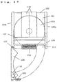
- reference numeral 35 is a defining unit formed in the lid 17. This defining unit 35 is for defining the rotation of the lid 17 by abutting against one end of the side wall 3c of the case main body 2.
- reference numeral 36 is a disk guide groove for holding and guiding the disk 1 discharged from the disk access 5.
- distance K see Fig. 13
- distance K from an inner circumferential end 51b of the opening 5b of the disk access 5 to the bottom of the disk guide groove 36 is set slightly larger than the diameter of the disk 1.
- the place set in this distance K is the narrowest position, except for the position of distance L mentioned later, in the route of passing of the disk 1, when the disk 1 is discharged.
- the distance L from the inner circumferential end 51b of the opening 5b of the disk access 5 to the leading end of the resin spring 22 of the lid 17 is set slightly smaller than the diameter of the disk 1 in the state of the resin spring 22 not deformed elastically.
- the resin spring 22 has a function of an elastic deforming abutting member.
- the move suppressing/stopping means of the invention is the means comprising the inner circumferential end 51b and the leading end of the resin spring 22.
- the abutting portion provided at a specific position of the lid of the invention corresponds to the resin spring 22, and the abutting portion provided near the disk access of the invention corresponds to the inner circumferential end 51b.
- a recording and reproducing device for recording and reproducing the disk contained in thus constituted cartridge is described by referring to Fig. 14.
- the constitution not relating to the invention is omitted.
- a disk motor 38 having a turntable 38a for mounting the disk 1 on, a pickup 39 for recording and reproducing, positioning pins 40a, 40b for defining the position of the cartridge, a rotatable shutter opener 41 being thrust by a spring for opening and closing the shutter 14, a write-inhibit switch 42 to be inserted into the write-inhibit hole 11a, and a cartridge detection switch 43 to be inserted into the discharge hole 25 for detecting whether the disk is taken out of the cartridge or not.
- the write-inhibit switch 42 detects the record forbid state when the leading end of the detection switch 42 can be inserted into the write-inhibit hole 11a of the disk cartridge in the embodiment being loaded in the recording and reproducing device, and when the leading end of the detection switch 42 abuts against the detection protrusion 27, thereby making it impossible to insert into the write-inhibit hole 11a, it is detected that the record is enabled.
- the cartridge detection switch 43 when the leading end of the detection switch 43 abuts against the stopping bar 23, detects that the cartridge has not past history of the contained disk 1 ever taken out of the cartridge. If the stopping bar 23 is already removed and the leading end of the detection switch 43 is inserted into the discharge hole 25 and there is nothing to abut against, it is detected that the cartridge has the history of its disk 1 once taken out of the cartridge.
- the shutter opener 41 When the cartridge of the embodiment is loaded into the cartridge holder (not shown) and inserted in the direction of arrow B (see Fig. 14), the shutter opener 41 is engaged with the opener concave part 13a of the slider 13 (see Fig. 5), and the slider 13 is moved by resisting the thrusting force of the torsion spring 16 (see Fig. 1), so that the shutter 14 moves in a direction of exposing the opening 9.
- the cartridge descends to the base stand 37 side by loading mechanism not shown, and two positioning pins 40a (see Fig. 14) provided on the base stand 37 are fitted into positioning holes 10a, 10b (see Fig.
- the recording and reproducing device shown in Fig. 14 recognizes as the cartridge not having past history of the disk ever being taken out, by the detection signal from the cartridge detection switch 43, and recognizes that the disk 1 is in recordable state, by the detection signal from the write-inhibit switch 42. Afterwards, by rotating the disk motor 38 and moving the pickup 39 to the specified place by pickup transfer means not shown, information is recorded in the disk 1 or information is read out from the disk 1.
- a pin with a thin end or the like is inserted into the moving hole 30 of the moving piece 27 from the write-inhibit hole 11b of the case main body 2, and the moving piece 27 is moved from the position shown in Fig. 7 to the position shown in Fig. 9, so that the leading end of the write-inhibit switch 42 may be inserted into the write-inhibit hole 11a.
- a moderate click feel is desired before and after the moving piece 27 rides over the convex part 11s for the sake of controllability.
- the detection protrusion 29 is easily visible from the write-inhibit hole 11a of the case main body 2, and the entire color of the moving piece 27 is different from the color of the case main body 2, so that it is easily judged visually from outside the case main body 2, whether the moving piece 27 is at the recordable position or at record forbid position.
- the leading end of a screwdriver is inserted from the stopping hole 24 formed in each side of the case main body 2, the groove of the stopping bar 23 (see Fig. 4) is inserted and rotated, two stopping bars 23 provided in the lid 17 are folded and removed, and are discharged from the discharge hole 25 provided in each side of the case main body 2.
- the lid 17 By holding the handle 26 of the lid 17 by hand, when turned in the direction of opening the lid 17, the detection protrusion 29 of the moving piece 27 slides in the write-inhibit hole 11a, and moves from the releasing position to the outside of the case main body 2. By further rotating, the lid 17 is opened to the maximum rotation position as shown in Fig. 13. In this state, when the case main body 2 is inclined, the disk 1 contained in the disk accommodating part 8 is guided along the straight lines 7b, 76c of the inner wall 7 by the action of gravity, and begins to move straightly toward the disk access 5 as indicated by arrow P in Fig. 13, and is discharged outside of the case main body 2 through the disk access 5.
- Fig. 13 shows the temporarily held state of the disk by the restoring force.
- the width of the case main body 2 may be set at 124 mm, and therefore it realizes the disk cartridge capable of taking out the disk by using the rotary lid, in spite of the outer dimension closer to 120 mm which is the diameter of the disk.
- the disk since the disk is held temporarily in the butting portion, the disk can be taken out by putting fingertip into the central hole 1a of the disk 1, in this held state, so that the information side of the disk is not touched, and the data reliability is enhanced.
- the operation is reverse to the procedure of taking out.
- Holding the central hole 1a and outer circumference of the disk 1 by finger it is inserted into the disk access, and is held by the resin spring 22.
- pushing the outer circumference of the disk 1 by finger engagement with the resin spring is cleared, and the disk 1 is slipped into the disk accommodating part 8.
- the clasp 19 of the lid is fitted into the clasp hole 20 of the case main body 2, and is fixed in the case main body 2.
- the stopping clasp 32 of the lid 17 is fitted into the concave part 33 of the upper case 3 and lower case 4 to hold the upper case 3 and lower case 5, so that lifting of the case main body 2 near the disk access 5 is prevented.
- the cartridge from which the disk is once removed can be distinguished because there is no stopping bar 23.
- the cartridge detection switch 43 is inserted into the discharge hole 25, and it is judged to be the cartridge from which the disk is once taken out. According to the judgement, the disk device gets into, for example, the mode for inspecting the information side, and judge whether recordable or not, thereby enhancing the reliability of recording.
- the cartridge of the embodiment is composed to deal with two-sided disk, and the shape is the same when the cartridge is turned upside down and loaded, so that the same operation is guaranteed.
- the lid 17 is dropped on the lower half 4 from above the inner side of the lower half 4.
- the pivot 17a is inserted into the rotary concave part 18, and the stopping bar 23 is inserted into the stopping hole 24, and the resin spring 22 is deformed and inserted into the straight portion 7b of the inner wall 7 of the lower half 4 by abutting.
- the stopping pawl 32 of the lid 17 abuts against the inner surface of the lower case 4, but when the lid 17 is further pushed down to the lower half 4 side, the stopping pawl 32 is elastically deformed toward the outer side of the lower case (right oblique downward direction in Fig. 1 and Fig.
- the slider 13 is placed at specified position. Then, dropping the upper half onto the lower half 4 from above the inner side of the lower half 5, the pivot 17a is inserted into the rotary concave part 18, and the stopping bar 23 is inserted into the stopping hole 24. Same as in the case of lower half 4, then, the upper half 3 is further pushed down so that the stopping pawl 32 of the lid 17 may be deformed elastically to ride over the upper half 3, and the stopping pawl 32 is fitted into the concave part 33. This ends mounting of the upper half 3.
- the case main body 2 is completely by fusing necessary positions of the upper half 3 and lower half 4 by ultrasonic wave.
- the torsion spring 16 is inserted and fixed into the case main body 2 from the opening, and the shutter 14 is fixed on the slider 13, thereby finishing the assembly.
- the disk cartridge capable of taking out the disk of the invention comprises a disk accommodating part for accommodating a disk rotatably therein, being in a nearly rectangular form, a case main body having at least one opening for inserting a disk motor and a pickup into the disk accommodating part, a shutter having a shielding plate for opening and closing the opening of the case main body, a disk access communicating with the disk accommodating part, allowing the disk to pass through the side wall of the case main body, a lid for opening and closing the disk access, as being rotatably supported on the case main body, and an abutting member for abutting against the disk outer circumferential end when releasing the lid, wherein a disk guide passage is formed so that the disk may be discharged from the disk access, in the released state of the lid, after the disk moves in a specified range along the inner surface of the side wall of the case main body, and abuts against the abutting member.
- the disk guide passage may be also formed so that the disk may change the
- the disk By forming the disk access from one end face of four end faces of the case main body to other end face adjacent to this end face, the disk can be taken out in the width of the cartridge nearly equal to the disk diameter by the rotary lid type, and dead space is nearly eliminated in the cartridge, and the width is same as that of the ordinary cartridge not capable of taking the disk, so that it may be easy to be compatible.
- the disk By forming the abutting member by using an elastic member that can be deformed elastically, the disk can be held by hand after once gripping and holding the moving disk by the abutting member, so that controllability and safety in disk discharge may be enhanced.
- the abutting position of the disk and abutting member can be set outside of the case main body, and the disk can be stopped once when popping out of the case main body, so that the disk can be held by hand more easily.
- the disk When the disk reaches the position of abutting against the disk stopping member as the abutting member, the disk can pass as being pressed and deformed by abutting against the disk, and adding such disk stopping member made of elastic member to the lid, the discharged disk can be held lightly at the position to be received by hand, so that the disk can be taken out more easily.
- the lid By providing the lid with a lock member for fixing and holding the lid by engaging with the case main body and thrusting means for turning in the lid opening direction when the engagement of the case main body and lock member is cleared, and using the thrusting means also as the abutting member made of elastic member, the opening and closing operation of the lid and the handling efficiency for taking out the disk can be enhanced.
- the disk can be taken out by putting finger into the central hole of the disk, and the disk can be taken out more easily, and the disk is not stained with fingerprint or the like.
- the handle for closing such notch in the lid the strength of the lid can be increased, and the lid can be opened and closed easily.
- the convex part is eliminated in the cartridge from which the disk is once taken out, and it can be distinguished visually and unnecessary confusion can be avoided.
- the device detects presence or absence of convex part, it can be judged whether the disk has been ever taken out of the cartridge or not, and the discharged disk may be, for example, inspected and the disk quality assurance can be judged.
- the disk By forming a moving piece for write-inhibit integrally in the lid, the disk can be taken out easily in the cartridge having write-inhibit hole.
- a gripping member By forming a gripping member to be engaged with upper and lower halves in the lid, lifting of the upper and lower halves near the disk access can be prevented, and therefore the strength and dimensional precision of the cartridge may be assured easily. Still more, by forming a stopping clasp at a free end of the griping member which can be deformed elastically, it is possible to assemble by inserting the gripping member into the upper and lower halves from above, so that the assembling efficiency is enhanced.
- an abutting member to abut against the outer circumferential end of the disk is provided, but not limited to this, for example, it may be composed to suppress or stop the move of the disk by using magnetic force, and in short it is enough as far as means for suppressing or stopping the move is provided for suppressing or stopping the move, when the disk is taken outside from the case main body through the disk access, after the move has moved a specific distance toward outside.
- the abutting part to abut against the outer circumferential end of the disk simultaneously is provided one each at the lid side and the case main body side, that is, two in total, and only the abutting member at the lid side is designed to be deformed elastically, but not limited to this, for example, as shown in Fig. 15, only the abutting member at the case main body may be designed to be deformed elastically, or the both may be deformed elastically. Or three or more abutting members may be provided.
- the difference from the foregoing embodiment is described while referring to Fig. 15.
- an abutting part (elastic stopping member) 901 is formed integrally on the upper half 3, being provided at the side wall 6b side of a main body case 902, a part of it serves as the inner circumferential end 51b of the opening 5b.
- the abutting part 901 is elastically deformed toward the direction of R shown in Fig. 15.
- a gap is provided between the abutting part 901 and side wall 6b, and this gap forms the pawl hole 20.
- a lid 117 is not provided with resin spring 22 (see Fig. 13) explained in the foregoing embodiment, and a disk guide groove 136 longer in overall length than the disk guide groove 36 shown in Fig.
- the abutting part for abutting against the outer circumferential end of the disk at the same time once stops the move of the disk and holds the disk temporarily, but not limited to this, for example, if the restoring force produced when the abutting part is deformed elastically when abutting simultaneously against the outer circumferential end of the disk is not so strong as to stop the move of the disk, it may be enough as far as the move of the disk is suppressed by the restoring force.
- At least two abutting parts including one abutting part that can be deformed elastically are provided, but not limited to this, for example, the abutting part may not be necessarily deformed elastically. That is, in such a case, as shown in Fig. 16, when the disk is taken outside, at least one abutting part is provided to abut against the outer circumferential end of the disk substantially from one side, and when the outer circumferential end of the disk abuts against the abutting part, there may be no abutting part on its outer circumferential end aside from this abutting portion.
- Fig. 16 As shown in Fig. 16. As shown in Fig.
- a lid 117 is not provided with resin spring (see Fig. 13) as explained in the foregoing embodiment, but a disk guide groove 136 same as shown in Fig. 15 is formed.
- a case main body 202 is not provided with an elastic deforming abutting part 901 as explained in Fig. 15, but an opening 5b is provided in part of the side wall 6b same as in the foregoing embodiment (see Fig. 2).
- distance M (see Fig. 16) from the inner circumferential end 51b of the opening 5b to the bottom of the disk guide groove 136 is set slightly larger than the diameter of the disk 1.
- the setting position of this distance M is the point of narrowest gap in the path of passing of the disk 1.
- the operation is as follows.
- the lid 117 is turned as shown in Fig. 16, and the lid 117 is opened to the maximum turning position.
- the disk 1 contained in the disk accommodating part 8 is guided along straight lines 7b, 7c of the inner wall 7 by the action of gravity, and begins to move straightly toward the disk access 5 as indicted by arrow P in Fig. 16, and it is discharged outside of the case main body 202 through the disk access 5.
- one side of the outer circumferential end of the disk abuts against the bottom of the disk guide groove 136 of the lid 117.
- the disk 1 changes the moving direction from direction P to direction Q along its bottom, and the moving speed drops.
- one side of the outer circumferential end of the disk 1 does not abut against the inner circumferential end 51b when moving in direction Q along the disk guide groove 36 of the lid 117.
- the outer circumferential end of the disk may abut against the inner circumferential end 51b of the opening 5b, but even in such a case, actually, the inner circumferential end 51b and the bottom of the disk guide groove 136 do not abut simultaneously against the outer circumferential end of the disk.
- the disk access is extended from one side wall out of four side walls of the case main body to other side wall adjacent to this side wall, but not limited to this, for example, if there is an allowance in the width dimension of the cartridge, the disk access may be formed in one side wall only.
- the elastic deforming abutting member (resin spring 22) that abuts against the disk when taking out the disk is used also as the thrusting means of the lid 17, but not limited to this, for example, the both functions may be provided independently without sharing.
- the central hole 1a of the disk is visible through the notch 12 of the case main body 2 when the disk is temporarily held in the abutting part, but not limited to this, for example, the end portion of the upper half 3 corresponding to the side wall 6a side of the case main body 2 may be dented in an arc form toward the central part of the case main body 2, that is, as far as the abutting part is composed so that the central hole of the disk is exposed outside from the case main body when the disk is at the position abutting against the abutting part, the shape of the case main body side is not particularly specified.
- the write-inhibit means is provided in the disk cartridge having the abutting part for suppressing or stopping the disk move, but not limited to this, for example, the write-inhibit means may be provided in the disk cartridge not having abutting part.
- the disk cartridge capable of taking out the disk comprises a case main body of a substantially rectangular form having a disk accommodating part for accommodating a data recording disk, and an opening provided so that disk driving means for rotating and driving the accommodated disk can be inserted into the disk accommodating part from outside, shutter means having a shielding plate for opening and closing the opening, a disk access provided at an end surface of the case main body to communicate with the disk accommodating part so that the disk can be taken in and out, a lid for opening and closing the disk access, and write-inhibit means formed on the lid for preventing accidental erasure of the recorded data on the disk at the time of recording operation into the disk.
- the write-inhibit means possesses a movable protrusion formed integrally on the lid, and a write-inhibit hole corresponding to the movable range of the protrusion formed on the case main body, and the protrusion is held at predetermined position showing record forbid or record enable state, depending on the convex or concave part provided at the inner side of the write-inhibit hole.
- the write-inhibit means is provided at least in the lid and is formed integrally with the lid, the write-inhibit means does not impede when taking out the disk, and the write-inhibit function can be realized in a simple structure.
- the disk access is extended from one end surface to other end surface adjacent to this end surface, out of substantially four end surfaces (that is, side walls) of the case main body, but not limited to this, for example, the disk access of such structure may be formed in the disk cartridge not having such abutting part.
- the disk cartridge capable of taking out the disk comprises a case main body of a substantially rectangular form having a disk accommodating part for accommodating a data recording disk, and an opening provided so that disk driving means for rotating and driving the accommodated disk can be inserted into the disk accommodating part from outside, shutter means having a shielding plate for opening and closing the opening, a disk access provided at an end surface of the case main body to communicate with the disk accommodating part so that the disk can be taken in and out, and a lid for opening and closing the disk access, wherein the disk access is extended from one end surface to other end surface adjacent to this end surface, out of substantially four end surfaces of the case main body. Therefore, the width of the case main body 2 may be set at 124 mm, and in spite of the outer dimension close to 120 mm which is the diameter of the disk, the disk cartridge capable of taking out the disk can be composed by using a rotary disk.
- the lid is of rotary type, but not limited to this, for example, the lid may be of detachable type.
- the abutting part is provided at the case main body side.
- the disk moves a specific range along the inner surface of the side wall of the case main body, then abuts against, for example, the abutting member and the moving speed of the disk drops, and the disk discharged outside through the disk access can be held easily by hand, so that controllability in disk discharge may be enhanced.
Landscapes
- Feeding And Guiding Record Carriers (AREA)
- Packaging For Recording Disks (AREA)
Applications Claiming Priority (4)
| Application Number | Priority Date | Filing Date | Title |
|---|---|---|---|
| JP24286795 | 1995-09-21 | ||
| JP242867/95 | 1995-09-21 | ||
| JP24286795 | 1995-09-21 | ||
| PCT/JP1996/002619 WO1997011463A1 (fr) | 1995-09-21 | 1996-09-13 | Cartouche a disquette amovible |
Publications (3)
| Publication Number | Publication Date |
|---|---|
| EP0794532A1 true EP0794532A1 (de) | 1997-09-10 |
| EP0794532A4 EP0794532A4 (de) | 1997-10-15 |
| EP0794532B1 EP0794532B1 (de) | 2003-11-26 |
Family
ID=17095429
Family Applications (1)
| Application Number | Title | Priority Date | Filing Date |
|---|---|---|---|
| EP96930385A Expired - Lifetime EP0794532B1 (de) | 1995-09-21 | 1996-09-13 | Kassette mit herausnehmbarer platte |
Country Status (8)
| Country | Link |
|---|---|
| US (2) | US5917803A (de) |
| EP (1) | EP0794532B1 (de) |
| JP (1) | JP3594314B2 (de) |
| KR (1) | KR100385999B1 (de) |
| CN (1) | CN1116679C (de) |
| DE (1) | DE69630868T2 (de) |
| TW (1) | TW416045B (de) |
| WO (1) | WO1997011463A1 (de) |
Cited By (11)
| Publication number | Priority date | Publication date | Assignee | Title |
|---|---|---|---|---|
| EP0926672A2 (de) * | 1997-12-24 | 1999-06-30 | TDK Corporation | Plattenkassette |
| EP0961274A2 (de) * | 1997-12-16 | 1999-12-01 | Matsushita Electric Industrial Co., Ltd. | Plattenkassette |
| EP0768665B1 (de) * | 1995-10-13 | 1999-12-22 | Kabushiki Kaisha Toshiba | Plattenkassette |
| EP1001427A2 (de) * | 1998-11-05 | 2000-05-17 | TDK Corporation | Plattenkassette mit Auszugsteil |
| EP1018739A2 (de) * | 1999-01-08 | 2000-07-12 | Alps Electric Co., Ltd. | Optische Plattenkassette |
| EP1018737A2 (de) * | 1999-01-08 | 2000-07-12 | Alps Electric Co., Ltd. | Optische Plattenkassette |
| WO2000054275A1 (en) * | 1999-03-05 | 2000-09-14 | Hitachi Maxell, Ltd. | Erasure prevention in disc cartridge |
| EP0768664B1 (de) * | 1995-10-13 | 2000-09-27 | Kabushiki Kaisha Toshiba | Plattenkassette |
| EP1067548A1 (de) * | 1999-06-04 | 2001-01-10 | Matsushita Electric Industrial Co., Ltd. | Plattenkassette |
| US6377538B1 (en) | 1998-11-18 | 2002-04-23 | Staar S.A. | Cartridge housing for recording discs |
| EP1244106A1 (de) * | 1996-10-28 | 2002-09-25 | Dai Nippon Printing Co., Ltd. | Kassettengehäuse für plattenförmigen Aufzeichnungsträger und Plattenkassette |
Families Citing this family (31)
| Publication number | Priority date | Publication date | Assignee | Title |
|---|---|---|---|---|
| JP3594314B2 (ja) * | 1995-09-21 | 2004-11-24 | 松下電器産業株式会社 | ディスク取り出し可能なディスクカートリッジ |
| US6324158B1 (en) * | 1996-02-28 | 2001-11-27 | Mitsubishi Denki Kabushiki Kaisha | Disk cartridge |
| JP3520431B2 (ja) * | 1996-03-15 | 2004-04-19 | 日立マクセル株式会社 | ディスクカートリッジ |
| EP0833330A1 (de) * | 1996-09-30 | 1998-04-01 | Kabushiki Kaisha Toshiba | Plattenkassette |
| EP0843310A1 (de) * | 1996-11-18 | 1998-05-20 | TDK Corporation | Plattenkassette |
| TW401311B (en) * | 1996-11-21 | 2000-08-11 | Nintendo Co Ltd | Information processing system and a method for finding genuineness therefor |
| US6307831B1 (en) * | 1997-06-10 | 2001-10-23 | Tdk Corporation | Disc cartridge having reference holes |
| US6400678B1 (en) * | 1998-03-06 | 2002-06-04 | Hitachi, Ltd. | Disc cartridge |
| US6625108B2 (en) * | 1998-03-06 | 2003-09-23 | Hitachi, Ltd. | Disk cartridge |
| US6449242B2 (en) | 1998-04-28 | 2002-09-10 | Hitachi, Ltd. | Disk cartridge |
| SG94718A1 (en) | 1998-05-23 | 2003-03-18 | Samsung Electronics Co Ltd | Cartridge for an information recording medium |
| US6496473B1 (en) * | 1998-07-02 | 2002-12-17 | Lg Electronics | Disc cartridge with mode selecting means |
| KR100560395B1 (ko) * | 1998-07-15 | 2006-09-20 | 엘지전자 주식회사 | 디스크카트리지 |
| SG107141A1 (en) | 1998-07-15 | 2004-11-29 | Samsung Electronics Co Ltd | Dis accommodating adaptor and a method and apparatus for driving the same |
| JP2000153891A (ja) * | 1998-09-17 | 2000-06-06 | Sony Corp | ディスク状記録媒体用のパッケ―ジ及びパッケ―ジシステム |
| US6078482A (en) * | 1998-10-16 | 2000-06-20 | Imation Corp. | Data storage cartridge with releasable shutter assembly |
| US6735154B2 (en) | 2001-01-31 | 2004-05-11 | Dphi Acquisitions, Inc. | Device and method for detecting cartridge readiness to load in a data storage system |
| US6906892B2 (en) * | 2001-01-31 | 2005-06-14 | Dphi Aquisitions, Inc. | Mechanism and method for positioning data cartridge in disk drive |
| US20020131201A1 (en) * | 2001-01-31 | 2002-09-19 | Dataplay, Inc. | Mechanism and method for limiting ejection of data cartridge from a disk drive |
| US6829120B2 (en) | 2001-01-31 | 2004-12-07 | Dphi Acquisitions, Inc. | Data cartridge load/unload mechanism for disk drive |
| JP2002367320A (ja) * | 2001-06-12 | 2002-12-20 | Hitachi Ltd | ディスクケース |
| WO2003041076A1 (en) * | 2001-11-09 | 2003-05-15 | Matsushita Electric Industrial Co., Ltd. | Disc cartridge |
| JP2003173648A (ja) * | 2001-12-04 | 2003-06-20 | Hitachi Ltd | ディスクカートリッジ |
| JP2004127372A (ja) * | 2002-09-30 | 2004-04-22 | Fuji Photo Film Co Ltd | ディスクカートリッジ |
| KR20050042706A (ko) * | 2003-11-04 | 2005-05-10 | 삼성전자주식회사 | 디스크 카트리지 |
| JPWO2005045839A1 (ja) | 2003-11-10 | 2007-05-24 | 松下電器産業株式会社 | ディスクカートリッジ |
| JP2005267784A (ja) * | 2004-03-19 | 2005-09-29 | Fuji Photo Film Co Ltd | ディスクカートリッジ |
| JP2005276338A (ja) * | 2004-03-25 | 2005-10-06 | Fuji Photo Film Co Ltd | ディスクカートリッジ |
| JPWO2006035768A1 (ja) * | 2004-09-28 | 2008-05-15 | 松下電器産業株式会社 | ディスクカートリッジ |
| US8516513B2 (en) * | 2009-01-06 | 2013-08-20 | Hitachi-Lg Data Storage, Inc. | Cassette with disk eject mechanism |
| JP2014049163A (ja) * | 2012-08-31 | 2014-03-17 | Toshiba Corp | 光ディスク用のカセット及びチェンジャ装置 |
Citations (6)
| Publication number | Priority date | Publication date | Assignee | Title |
|---|---|---|---|---|
| EP0368347A2 (de) * | 1988-11-11 | 1990-05-16 | Sony Corporation | Plattenkassette |
| EP0421775A2 (de) * | 1989-10-06 | 1991-04-10 | Sony Corporation | Plattenkassette |
| GB2272990A (en) * | 1992-11-30 | 1994-06-01 | Hitachi Maxell | Disk cartridge |
| EP0617425A2 (de) * | 1993-03-23 | 1994-09-28 | Matsushita Electric Industrial Co., Ltd. | Adaptateur für Kassette und Kassette für Epfang in dem Adaptateur |
| EP0691653A1 (de) * | 1994-07-04 | 1996-01-10 | Shih-Hsien Lin | Behälter zum Tragen von Compact Discs |
| EP0768662A1 (de) * | 1995-10-13 | 1997-04-16 | Kabushiki Kaisha Toshiba | Plattenkassette |
Family Cites Families (10)
| Publication number | Priority date | Publication date | Assignee | Title |
|---|---|---|---|---|
| JPH01159274A (ja) * | 1987-12-16 | 1989-06-22 | Seiko Epson Corp | プリンタ |
| JPH01232588A (ja) * | 1988-03-11 | 1989-09-18 | Sony Corp | ディスクカートリッジ |
| NL8800820A (nl) * | 1988-03-31 | 1989-10-16 | Philips Nv | Cassette. |
| JP2658781B2 (ja) * | 1992-11-11 | 1997-09-30 | ソニー株式会社 | ディスクカートリッジ |
| JP3513194B2 (ja) * | 1993-10-22 | 2004-03-31 | キヤノン株式会社 | 撮像装置 |
| JP3594314B2 (ja) * | 1995-09-21 | 2004-11-24 | 松下電器産業株式会社 | ディスク取り出し可能なディスクカートリッジ |
| JP2816120B2 (ja) * | 1995-10-13 | 1998-10-27 | 株式会社東芝 | ディスクカートリッジ装置 |
| JP3495158B2 (ja) * | 1995-10-30 | 2004-02-09 | 株式会社東芝 | ディスクカートリッジ装置 |
| JP3516089B2 (ja) * | 1996-02-26 | 2004-04-05 | 日立マクセル株式会社 | ディスクカートリッジ |
| JP3491118B2 (ja) * | 1996-03-28 | 2004-01-26 | 日立マクセル株式会社 | ディスクカートリッジ |
-
1996
- 1996-09-13 JP JP51258597A patent/JP3594314B2/ja not_active Expired - Lifetime
- 1996-09-13 WO PCT/JP1996/002619 patent/WO1997011463A1/ja active IP Right Grant
- 1996-09-13 KR KR1019970703410A patent/KR100385999B1/ko not_active IP Right Cessation
- 1996-09-13 DE DE69630868T patent/DE69630868T2/de not_active Expired - Lifetime
- 1996-09-13 EP EP96930385A patent/EP0794532B1/de not_active Expired - Lifetime
- 1996-09-13 CN CN96191098.4A patent/CN1116679C/zh not_active Expired - Fee Related
- 1996-09-18 TW TW085111427A patent/TW416045B/zh not_active IP Right Cessation
- 1996-09-20 US US08/710,732 patent/US5917803A/en not_active Expired - Lifetime
-
1999
- 1999-05-05 US US09/310,697 patent/US6078563A/en not_active Expired - Fee Related
Patent Citations (6)
| Publication number | Priority date | Publication date | Assignee | Title |
|---|---|---|---|---|
| EP0368347A2 (de) * | 1988-11-11 | 1990-05-16 | Sony Corporation | Plattenkassette |
| EP0421775A2 (de) * | 1989-10-06 | 1991-04-10 | Sony Corporation | Plattenkassette |
| GB2272990A (en) * | 1992-11-30 | 1994-06-01 | Hitachi Maxell | Disk cartridge |
| EP0617425A2 (de) * | 1993-03-23 | 1994-09-28 | Matsushita Electric Industrial Co., Ltd. | Adaptateur für Kassette und Kassette für Epfang in dem Adaptateur |
| EP0691653A1 (de) * | 1994-07-04 | 1996-01-10 | Shih-Hsien Lin | Behälter zum Tragen von Compact Discs |
| EP0768662A1 (de) * | 1995-10-13 | 1997-04-16 | Kabushiki Kaisha Toshiba | Plattenkassette |
Non-Patent Citations (1)
| Title |
|---|
| See also references of WO9711463A1 * |
Cited By (31)
| Publication number | Priority date | Publication date | Assignee | Title |
|---|---|---|---|---|
| EP0768665B1 (de) * | 1995-10-13 | 1999-12-22 | Kabushiki Kaisha Toshiba | Plattenkassette |
| EP0768664B1 (de) * | 1995-10-13 | 2000-09-27 | Kabushiki Kaisha Toshiba | Plattenkassette |
| EP1244106A1 (de) * | 1996-10-28 | 2002-09-25 | Dai Nippon Printing Co., Ltd. | Kassettengehäuse für plattenförmigen Aufzeichnungsträger und Plattenkassette |
| US6392987B1 (en) | 1997-12-16 | 2002-05-21 | Matsushita Electric Industrial Co., Ltd. | Disk cartridge and adapter with locking and misinsertion preventing mechanism for the cover |
| EP0961274A2 (de) * | 1997-12-16 | 1999-12-01 | Matsushita Electric Industrial Co., Ltd. | Plattenkassette |
| US6288999B1 (en) | 1997-12-16 | 2001-09-11 | Matsushita Electric Industrial Co., Ltd | Disk cartridge and adapter |
| US6215761B1 (en) | 1997-12-16 | 2001-04-10 | Matsushita Electric Industrial Co., Ltd. | Disk cartridge |
| US6430147B1 (en) | 1997-12-16 | 2002-08-06 | Matushita Electric Industrial Co., Ltd. | Disk cartridge and adapter |
| US6172962B1 (en) | 1997-12-16 | 2001-01-09 | Matsushita Electric Industrial Co., Ltd. | Disk cartridge with finger-like holding members and three-part supporting feature |
| EP0961274A3 (de) * | 1997-12-16 | 1999-12-22 | Matsushita Electric Industrial Co., Ltd. | Plattenkassette |
| US6351450B1 (en) | 1997-12-16 | 2002-02-26 | Matsushita Electric Industrial Co., Ltd. | Disk cartridge and adapter |
| EP0926672A2 (de) * | 1997-12-24 | 1999-06-30 | TDK Corporation | Plattenkassette |
| EP0926672A3 (de) * | 1997-12-24 | 1999-09-15 | TDK Corporation | Plattenkassette |
| US6370108B1 (en) | 1997-12-24 | 2002-04-09 | Tdk Corporation | Disc cartridge |
| US6418113B1 (en) | 1998-11-05 | 2002-07-09 | Tdk Corporation | Disk cartridge |
| EP1001427A2 (de) * | 1998-11-05 | 2000-05-17 | TDK Corporation | Plattenkassette mit Auszugsteil |
| EP1001427A3 (de) * | 1998-11-05 | 2001-09-19 | TDK Corporation | Plattenkassette mit Auszugsteil |
| US6377538B1 (en) | 1998-11-18 | 2002-04-23 | Staar S.A. | Cartridge housing for recording discs |
| US6396800B1 (en) | 1999-01-08 | 2002-05-28 | Alps Electric Co., Ltd. | Optical disk cartridge |
| EP1018739A3 (de) * | 1999-01-08 | 2000-08-09 | Alps Electric Co., Ltd. | Optische Plattenkassette |
| EP1018737A3 (de) * | 1999-01-08 | 2000-08-09 | Alps Electric Co., Ltd. | Optische Plattenkassette |
| US6424617B1 (en) | 1999-01-08 | 2002-07-23 | Alps Electric Co., Ltd. | Optical disk cartridge |
| EP1018737A2 (de) * | 1999-01-08 | 2000-07-12 | Alps Electric Co., Ltd. | Optische Plattenkassette |
| EP1018739A2 (de) * | 1999-01-08 | 2000-07-12 | Alps Electric Co., Ltd. | Optische Plattenkassette |
| WO2000054275A1 (en) * | 1999-03-05 | 2000-09-14 | Hitachi Maxell, Ltd. | Erasure prevention in disc cartridge |
| US6504679B1 (en) | 1999-03-05 | 2003-01-07 | Hitachi Maxell, Ltd. | Erasure prevention in disc cartridge |
| EP1178488A2 (de) * | 1999-06-04 | 2002-02-06 | Matsushita Electric Industrial Co., Ltd. | Plattenkassette |
| EP1067548A1 (de) * | 1999-06-04 | 2001-01-10 | Matsushita Electric Industrial Co., Ltd. | Plattenkassette |
| US6463029B1 (en) | 1999-06-04 | 2002-10-08 | Matsushita Electrical Industrial Co., Ltd. | Disc cartridge including a disc holder with a flexible member |
| US6590859B2 (en) | 1999-06-04 | 2003-07-08 | Matsushita Electric Industrial, Co Ltd. | Disc cartridge |
| EP1178488A3 (de) * | 1999-06-04 | 2006-11-29 | Matsushita Electric Industrial Co., Ltd. | Plattenkassette |
Also Published As
| Publication number | Publication date |
|---|---|
| DE69630868T2 (de) | 2004-04-15 |
| EP0794532B1 (de) | 2003-11-26 |
| JP3594314B2 (ja) | 2004-11-24 |
| US5917803A (en) | 1999-06-29 |
| KR987000657A (ko) | 1998-03-30 |
| US6078563A (en) | 2000-06-20 |
| CN1165577A (zh) | 1997-11-19 |
| DE69630868D1 (de) | 2004-01-08 |
| EP0794532A4 (de) | 1997-10-15 |
| KR100385999B1 (ko) | 2003-10-10 |
| WO1997011463A1 (fr) | 1997-03-27 |
| CN1116679C (zh) | 2003-07-30 |
| TW416045B (en) | 2000-12-21 |
Similar Documents
| Publication | Publication Date | Title |
|---|---|---|
| US5917803A (en) | Disk cartridge capable of taking out a disk | |
| US6172962B1 (en) | Disk cartridge with finger-like holding members and three-part supporting feature | |
| KR100366112B1 (ko) | 디스크카트리지 | |
| EP1363288B1 (de) | Plattenkassette | |
| EP0974972B1 (de) | Plattenkassette | |
| EP0973163B1 (de) | Plattenkassette | |
| EP0533463B1 (de) | Plattenkassette mit Falschaufzeichnungsschutzmechanismus | |
| GB2272990A (en) | Disk cartridge | |
| US6052359A (en) | Disk cartridge having a dynamically stable supported member in a discrimination hole | |
| EP1443513B1 (de) | Kassette als behälter für ein aufzeichnungsmedium | |
| JP2000090627A (ja) | ディスクカ―トリッジ | |
| KR100269991B1 (ko) | 기록매체의 식별장치 | |
| JPS60163287A (ja) | 記録再生装置の誤消去防止装置 | |
| JPH103775A (ja) | ディスクカートリッジ | |
| KR20010087223A (ko) | 디스크 카트리지 | |
| CA2384666C (en) | Disk cartridge and adapter | |
| JP2844644B2 (ja) | ディスク用カートリッジケース及び情報記録再生装置 | |
| JP2001143359A (ja) | ディスク駆動装置 | |
| JPH0594689A (ja) | デイスクカートリツジの誤記録防止機構 | |
| JPH097345A (ja) | 磁気ディスクカートリッジ | |
| KR20060126423A (ko) | 디스크 카트리지 | |
| JPH103774A (ja) | ディスクカートリッジ | |
| JPS61289586A (ja) | 記録媒体収納体 | |
| US20080019046A1 (en) | Disk Cartridge | |
| JP2000260158A (ja) | ディスクカートリッジ |
Legal Events
| Date | Code | Title | Description |
|---|---|---|---|
| PUAI | Public reference made under article 153(3) epc to a published international application that has entered the european phase |
Free format text: ORIGINAL CODE: 0009012 |
|
| AK | Designated contracting states |
Kind code of ref document: A1 Designated state(s): DE FR GB IT NL |
|
| A4 | Supplementary search report drawn up and despatched | ||
| AK | Designated contracting states |
Kind code of ref document: A4 Designated state(s): DE FR GB IT NL |
|
| 17P | Request for examination filed |
Effective date: 19970918 |
|
| 17Q | First examination report despatched |
Effective date: 20020419 |
|
| GRAH | Despatch of communication of intention to grant a patent |
Free format text: ORIGINAL CODE: EPIDOS IGRA |
|
| GRAS | Grant fee paid |
Free format text: ORIGINAL CODE: EPIDOSNIGR3 |
|
| GRAA | (expected) grant |
Free format text: ORIGINAL CODE: 0009210 |
|
| AK | Designated contracting states |
Kind code of ref document: B1 Designated state(s): DE FR GB IT NL |
|
| REG | Reference to a national code |
Ref country code: GB Ref legal event code: FG4D |
|
| REF | Corresponds to: |
Ref document number: 69630868 Country of ref document: DE Date of ref document: 20040108 Kind code of ref document: P |
|
| ET | Fr: translation filed | ||
| PLBE | No opposition filed within time limit |
Free format text: ORIGINAL CODE: 0009261 |
|
| STAA | Information on the status of an ep patent application or granted ep patent |
Free format text: STATUS: NO OPPOSITION FILED WITHIN TIME LIMIT |
|
| 26N | No opposition filed |
Effective date: 20040827 |
|
| PGFP | Annual fee paid to national office [announced via postgrant information from national office to epo] |
Ref country code: IT Payment date: 20100915 Year of fee payment: 15 Ref country code: FR Payment date: 20100921 Year of fee payment: 15 |
|
| PGFP | Annual fee paid to national office [announced via postgrant information from national office to epo] |
Ref country code: GB Payment date: 20100908 Year of fee payment: 15 |
|
| PGFP | Annual fee paid to national office [announced via postgrant information from national office to epo] |
Ref country code: NL Payment date: 20100916 Year of fee payment: 15 |
|
| PGFP | Annual fee paid to national office [announced via postgrant information from national office to epo] |
Ref country code: DE Payment date: 20100908 Year of fee payment: 15 |
|
| REG | Reference to a national code |
Ref country code: NL Ref legal event code: V1 Effective date: 20120401 |
|
| GBPC | Gb: european patent ceased through non-payment of renewal fee |
Effective date: 20110913 |
|
| PG25 | Lapsed in a contracting state [announced via postgrant information from national office to epo] |
Ref country code: IT Free format text: LAPSE BECAUSE OF NON-PAYMENT OF DUE FEES Effective date: 20110913 |
|
| REG | Reference to a national code |
Ref country code: FR Ref legal event code: ST Effective date: 20120531 |
|
| REG | Reference to a national code |
Ref country code: DE Ref legal event code: R119 Ref document number: 69630868 Country of ref document: DE Effective date: 20120403 |
|
| PG25 | Lapsed in a contracting state [announced via postgrant information from national office to epo] |
Ref country code: NL Free format text: LAPSE BECAUSE OF NON-PAYMENT OF DUE FEES Effective date: 20120401 Ref country code: DE Free format text: LAPSE BECAUSE OF NON-PAYMENT OF DUE FEES Effective date: 20120403 |
|
| PG25 | Lapsed in a contracting state [announced via postgrant information from national office to epo] |
Ref country code: FR Free format text: LAPSE BECAUSE OF NON-PAYMENT OF DUE FEES Effective date: 20110930 Ref country code: GB Free format text: LAPSE BECAUSE OF NON-PAYMENT OF DUE FEES Effective date: 20110913 |