EP0794315B1 - Dispositif pour forer dans le sol - Google Patents
Dispositif pour forer dans le sol Download PDFInfo
- Publication number
- EP0794315B1 EP0794315B1 EP97102510A EP97102510A EP0794315B1 EP 0794315 B1 EP0794315 B1 EP 0794315B1 EP 97102510 A EP97102510 A EP 97102510A EP 97102510 A EP97102510 A EP 97102510A EP 0794315 B1 EP0794315 B1 EP 0794315B1
- Authority
- EP
- European Patent Office
- Prior art keywords
- rod
- transverse
- push
- rod assembly
- recesses
- Prior art date
- Legal status (The legal status is an assumption and is not a legal conclusion. Google has not performed a legal analysis and makes no representation as to the accuracy of the status listed.)
- Expired - Lifetime
Links
- 238000005553 drilling Methods 0.000 title claims description 12
- 239000002689 soil Substances 0.000 title description 4
- 238000010168 coupling process Methods 0.000 claims description 43
- 230000008878 coupling Effects 0.000 claims description 42
- 238000005859 coupling reaction Methods 0.000 claims description 42
- 210000001331 nose Anatomy 0.000 claims description 17
- 230000000295 complement effect Effects 0.000 claims description 9
- 239000007787 solid Substances 0.000 claims description 3
- 230000000903 blocking effect Effects 0.000 claims 2
- 210000003128 head Anatomy 0.000 description 9
- 230000009172 bursting Effects 0.000 description 4
- XEEYBQQBJWHFJM-UHFFFAOYSA-N iron Substances [Fe] XEEYBQQBJWHFJM-UHFFFAOYSA-N 0.000 description 3
- 238000004519 manufacturing process Methods 0.000 description 3
- 238000005452 bending Methods 0.000 description 2
- 239000007822 coupling agent Substances 0.000 description 2
- 238000006073 displacement reaction Methods 0.000 description 2
- 230000000694 effects Effects 0.000 description 2
- 229910052742 iron Inorganic materials 0.000 description 2
- 108091008747 NR2F3 Proteins 0.000 description 1
- 238000005299 abrasion Methods 0.000 description 1
- 238000005520 cutting process Methods 0.000 description 1
- 230000002996 emotional effect Effects 0.000 description 1
- 230000007774 longterm Effects 0.000 description 1
- 239000011295 pitch Substances 0.000 description 1
- 238000002360 preparation method Methods 0.000 description 1
- 238000003825 pressing Methods 0.000 description 1
- 230000003068 static effect Effects 0.000 description 1
Images


Classifications
-
- F—MECHANICAL ENGINEERING; LIGHTING; HEATING; WEAPONS; BLASTING
- F16—ENGINEERING ELEMENTS AND UNITS; GENERAL MEASURES FOR PRODUCING AND MAINTAINING EFFECTIVE FUNCTIONING OF MACHINES OR INSTALLATIONS; THERMAL INSULATION IN GENERAL
- F16L—PIPES; JOINTS OR FITTINGS FOR PIPES; SUPPORTS FOR PIPES, CABLES OR PROTECTIVE TUBING; MEANS FOR THERMAL INSULATION IN GENERAL
- F16L55/00—Devices or appurtenances for use in, or in connection with, pipes or pipe systems
- F16L55/16—Devices for covering leaks in pipes or hoses, e.g. hose-menders
- F16L55/162—Devices for covering leaks in pipes or hoses, e.g. hose-menders from inside the pipe
- F16L55/165—Devices for covering leaks in pipes or hoses, e.g. hose-menders from inside the pipe a pipe or flexible liner being inserted in the damaged section
- F16L55/1658—Devices for covering leaks in pipes or hoses, e.g. hose-menders from inside the pipe a pipe or flexible liner being inserted in the damaged section the old pipe being ruptured prior to insertion of a new pipe
-
- E—FIXED CONSTRUCTIONS
- E21—EARTH OR ROCK DRILLING; MINING
- E21B—EARTH OR ROCK DRILLING; OBTAINING OIL, GAS, WATER, SOLUBLE OR MELTABLE MATERIALS OR A SLURRY OF MINERALS FROM WELLS
- E21B17/00—Drilling rods or pipes; Flexible drill strings; Kellies; Drill collars; Sucker rods; Cables; Casings; Tubings
- E21B17/02—Couplings; joints
- E21B17/04—Couplings; joints between rod or the like and bit or between rod and rod or the like
- E21B17/046—Couplings; joints between rod or the like and bit or between rod and rod or the like with ribs, pins, or jaws, and complementary grooves or the like, e.g. bayonet catches
-
- E—FIXED CONSTRUCTIONS
- E21—EARTH OR ROCK DRILLING; MINING
- E21B—EARTH OR ROCK DRILLING; OBTAINING OIL, GAS, WATER, SOLUBLE OR MELTABLE MATERIALS OR A SLURRY OF MINERALS FROM WELLS
- E21B17/00—Drilling rods or pipes; Flexible drill strings; Kellies; Drill collars; Sucker rods; Cables; Casings; Tubings
- E21B17/22—Rods or pipes with helical structure
-
- E—FIXED CONSTRUCTIONS
- E21—EARTH OR ROCK DRILLING; MINING
- E21B—EARTH OR ROCK DRILLING; OBTAINING OIL, GAS, WATER, SOLUBLE OR MELTABLE MATERIALS OR A SLURRY OF MINERALS FROM WELLS
- E21B19/00—Handling rods, casings, tubes or the like outside the borehole, e.g. in the derrick; Apparatus for feeding the rods or cables
- E21B19/08—Apparatus for feeding the rods or cables; Apparatus for increasing or decreasing the pressure on the drilling tool; Apparatus for counterbalancing the weight of the rods
- E21B19/086—Apparatus for feeding the rods or cables; Apparatus for increasing or decreasing the pressure on the drilling tool; Apparatus for counterbalancing the weight of the rods with a fluid-actuated cylinder
-
- E—FIXED CONSTRUCTIONS
- E21—EARTH OR ROCK DRILLING; MINING
- E21B—EARTH OR ROCK DRILLING; OBTAINING OIL, GAS, WATER, SOLUBLE OR MELTABLE MATERIALS OR A SLURRY OF MINERALS FROM WELLS
- E21B7/00—Special methods or apparatus for drilling
- E21B7/20—Driving or forcing casings or pipes into boreholes, e.g. sinking; Simultaneously drilling and casing boreholes
- E21B7/205—Driving or forcing casings or pipes into boreholes, e.g. sinking; Simultaneously drilling and casing boreholes without earth removal
- E21B7/206—Driving or forcing casings or pipes into boreholes, e.g. sinking; Simultaneously drilling and casing boreholes without earth removal using down-hole drives
-
- E—FIXED CONSTRUCTIONS
- E21—EARTH OR ROCK DRILLING; MINING
- E21B—EARTH OR ROCK DRILLING; OBTAINING OIL, GAS, WATER, SOLUBLE OR MELTABLE MATERIALS OR A SLURRY OF MINERALS FROM WELLS
- E21B7/00—Special methods or apparatus for drilling
- E21B7/28—Enlarging drilled holes, e.g. by counterboring
- E21B7/30—Enlarging drilled holes, e.g. by counterboring without earth removal
Definitions
- the invention relates to a device for drilling in Soil, especially for the manufacture or expansion of Earth drilling and / or for smashing old pipelines as well as for laying new pipes a push-pull unit and a drive connection with it standing, through the earth hole or the pipeline guided linkage.
- the manufacture or expansion of earth bores and / or the smashing of old pipes as well as the laying new pipelines can be dynamically driven generating ram boring machines or by means of presses or Winches that generate static pressure and that Pushing or pulling the linkage forward can be effected.
- the disadvantage with dynamic-working ram boring machines is the disadvantage connected that they make loud noises when working generate damage to the environment through the vibrations, especially at parallel or crossing Foreign lines can cause and oily ones Exhaust air that is harmful to the environment.
- statically acting presses and winches are cumbersome to handle and can only be pushing with a rigid rod or pulling under Use ropes.
- the shear-resistant linkage must, because the push device in usually from a pit or a shaft works, consist of individual short rod parts. Gradually, each one the diameter of the Pit or shaft part length corresponding to the shaft is pressed into the ground or the old pipeline the linkage can be extended by a section. There the manholes usually have an inner diameter of 1 m, the single rod lengths can often be no longer than 80 cm.
- the device To push a linkage into the To press soil, the device must be directly on the Attack the linkage for what on the outer surface of the Linkage attacking jaws can be used.
- a drilling device known from French patent 527 075 is used as a drive a thrust unit, which is connected to a linkage in drive connection stands with holes for inserting pins is attacked by coupling means of the thrust unit.
- a drilling device is from the German patent specification 474 493 known with a linkage made of U-iron or double-T iron, the one-sided are hinged to one another with the help of a Lifting device to enable drilling up on a cam track.
- U.S. Patent 4,062,412 describes a drilling device with a rotary-push drive and a linkage made of individual Sections that are loosely inserted into one another in order to drill a curve enable.
- the propulsion takes place with a thrust drive, which Linkage moved forward gradually.
- a thrust drive which Linkage moved forward gradually.
- swivel tabs of the drive in recesses of the Linkage.
- the swivel tabs leave the recesses during the reverse stroke again.
- the problem lies with the invention to provide a device of the type mentioned at the outset improve that both for pushing and pulling a Linkage is suitable and wear due to slipping of the push-pull unit avoided on the linkage.
- the invention proposes a drilling device type mentioned at the beginning with a push-pull unit, one with it Drive linkage standing rods with projections and / or recesses and alternately on the projections or the recesses attacking positive coupling means in the form of a cross Slidable to the boom, the boom against the direction of advance locking pawl and one linear from the push-pull unit driven pawl in front, the invention transverse to the linkage or driving direction is slidably arranged.
- the linkage can be designed as a rack or ladder-like with rungs be or have ring or spiral grooves.
- the coupling agent can from at least one in a rack or ring or spiral grooves engaging or engaging the rungs or projections Locking elements exist.
- the linkage can be composed of individual rod parts or be designed as a link chain.
- the coupling agents consist of engaging at least one projection or engaging in a recess, linearly driven by the push-pull unit Locking elements so that the linkage can be moved step by step.
- the boom consists of individual, assembled rod parts it is advantageous if this is delimited by transverse walls at one end Cross opening and at the other end a coupling head with a die Transverse opening of a rod part to be coupled and one Nose under cross wall, one overlapping the other cross wall Recess and one the other transverse wall on the outside when thrust have a subtle nose.
- the transverse walls preferably have noses which fit under them Cutouts on.
- the transverse opening can between the last and the penultimate rung forming the transverse walls and the rungs can have cutouts for the noses.
- the rod parts are solid with at least one-sided, regularly spaced recesses for the coupling means are, the transverse opening at one end of a rod part arrange with a coupling head at the other end.
- rod parts have one at each end complementary bayonet coupling head from about half the width of the rod part corresponding longitudinal tab with a recess on front, outer end of the tab and a complementary nose the rod part, parallel to the bracket and with an earth pin on the Longitudinal tab of one part of the rod and a complementary cross hole have in the longitudinal tab of the other rod part.
- the holes are dimensioned so that the cross pin of a rod part in the Cross hole in an angled position of the two rod parts into each other leave it in a stretched, aligned position the lugs engaging in the recesses are locked.
- the linearly movable push-pull unit carry out a return stroke after the working stroke, but this should be the case Booms are not moved. It is then advantageous if not on one moving part of the push-pull unit a transverse, this part opposite to the drive direction with the rod parts or the Articulated chain coupling or clamping pawl is arranged.
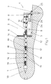
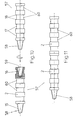
- a push-pull unit 4 is arranged in the pit 3.
- Your standing still Mount 5 is supported by a pressure plate 6 on a wall of the ground 1 and is held by means of one or more ground anchors 7.
- a hydraulic piston-cylinder unit 8 is arranged, the one Slide 9 back and forth linearly.
- Guide pin pairs 10 in Carriages 9 serve to guide a rod part 15 of a drill pipe.
- Further rod parts 14 are with the rod part held in the carriage 9 14 coupled.
- the bore is made by driving in a drill bit 13 of the rod consisting of the rod parts 14 into the ground 1 manufactured.
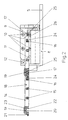
- the rod parts 14 are ladder-like with rungs 15 and parallel bars 18 educated.
- each rod part 14 At one end of each rod part 14 is a coupling head 19 arranged with a penultimate rung and a last rung 17th of an adjacent rod part 14 cooperates.
- the coupling head 19 is provided with a recess 20 which overlaps the last rung 17.
- a nose 21 on the coupling head 19 engages in a cutout 24 of the penultimate Rung 16, while a nose 22 in a cutout 25 in the last rung 17 engages.
- Fig. 2 the push-pull unit 4 is shown at the end of its feed stroke. If the carriage 9 by means of the hydraulic piston-cylinder unit 8 in retracted the position shown in Fig. 1, prevents the Lafette the push-pull unit 4 arranged pawl 12 that the 14 rods consisting of the rod parts with the carriage 5 backwards emotional.
- the pawls 11, 12 can be resilient in that shown in FIGS. 1 and 2 Be held so that they are only if there is a rung 15,16,17 or have a coupling head 19 moved past them, have them pushed back, to then return to the position shown. It is also possible to actuate the pawls 11, 12 mechanically, electrically or hydraulically.
- an old pipe 28 by a new one To replace pipeline 31 are gradually to each other rod parts 14 coupled to a rod from a duct shaft 27 from through the old pipe 28 to an adjacent, not shown Channel shaft pushed. Then a burst head 29 with the Coupling head 19 of the last rod part 14 coupled, during that Rod part 14, which is in the manhole 27 in the area of the push-pull unit 4 is located by the hydraulic piston-cylinder unit 8, which is a shift of the carriage causes, is pulled into the channel shaft 27.
- the old pipeline 28 is smashed by means of the bursting head 29; at the same time, an enlarged earth hole 30 is created and one with the pulling pipe 31 connected to the bursting head 29, which is the new pipeline represents, drawn into the earth bore 30.
- a pressure medium driven ram boring machine 32 is arranged be the pressure medium via a pressure medium line 33 in the draw tube 31 is supplied.
- the impacts of the ram boring machine 32 cause one rapid demolition of the old pipeline 28.
- ram boring machine 32 can be arranged on the bursting head 29 erectable cutting by a Radial movement of locally increased, high forces on the old pipeline 28 apply and tear it open.
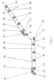
- rod parts 34 are shown, which are not ladder-like, but are solid and have side projections 35 into the pawls, similar to the pawls 11, 12 according to FIGS. 1 to 4, for the feed can intervene.
- each rod part 34 At one end of each rod part 34 is a coupling head 42 arranged, which is provided with a recess 43 and lugs 44, 45, while at the other end there is a transverse opening 37 which is from Transverse walls 38,39 is limited so that the coupling head 42 through swing this transverse opening 37 in for coupling with a further rod part 34 leaves.
- the lugs 44, 45 then engage in the cutouts 40, 41, so that also this version a shear-resistant coupling is guaranteed.
- FIG. 7 to 9 is another embodiment of a shear-resistant coupling between Rod parts 48 shown.
- These rod parts are ladder-like; however, only the parallel longitudinal bars as well as a bayonet coupling heads are 51, 52 adjacent section 50 is shown.
- the bayonet coupling head 51 is as extending in the longitudinal direction of the rod part 48 Flap formed, which has a thickness of about half the width of the Rod part 48 has.
- the end of the bayonet coupling head 51 is with a recess 53 provided with a complementary nose 54 on Rod part 48 cooperates.
- the bayonet coupling head 51 has one Cross pin 55, which has a transverse bore 56 on the bayonet coupling head 52 interacts.
- transverse bore 56 is designed as an elongated hole, it can act under thrust a slight relative displacement on the rod parts 48 enter the vertical surfaces of the bayonet coupling heads 51,52 brings together to the system, so that the rod parts 48 shear resistant are interconnected.
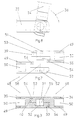
- rod parts 57 which are round or square Have cross-section and at one end with a conical External thread 58 and at the other end with a bore 59 with a conical Internal threads are provided.
- the rod parts 57 can thus be easily screw together and form in this way a rigid rod.
- the coupling means of the push-pull unit can engage in recesses 60 formed as ring grooves. Instead of the ring grooves on the outer surface of the rod parts 57 also spiral grooves can be arranged.
- the link chain can be from a drum in the Unwind pit 3 or in shaft 27 or outside of it or on top of it wind up without having to interrupt work because of the preparation of rod parts are required.
- the feed can be with a link chain both by a linear drive and by a rotary drive accomplish.
- a shear-resistant coupling between the individual chain links can be achieved if in the joints of the chain links there is an axial movement possibility, so that complementary shaped surfaces of adjacent chain links when exposed to a Apply thrust to each other and create a rigid coupling.
Landscapes
- Engineering & Computer Science (AREA)
- Geology (AREA)
- Life Sciences & Earth Sciences (AREA)
- Mining & Mineral Resources (AREA)
- Physics & Mathematics (AREA)
- Environmental & Geological Engineering (AREA)
- Fluid Mechanics (AREA)
- General Life Sciences & Earth Sciences (AREA)
- Geochemistry & Mineralogy (AREA)
- Mechanical Engineering (AREA)
- General Engineering & Computer Science (AREA)
- Earth Drilling (AREA)
- Excavating Of Shafts Or Tunnels (AREA)
Claims (15)
- Dispositif pour forer le sol comprenant une unité de poussée et de traction (4), une tringlerie (14, 34, 48, 57) qui est en liaison d'entraínement avec cette dernière, des saillies (15, 35) et/ou des évidements (36, 60) sur la tringlerie (14, 34, 48, 57) et des moyens d'accouplement (11, 12) par engagement positif agissant tantôt sur les saillies (15, 35), tantôt sur les évidements (36, 60), qui se présentent sous la forma d'un cliquet d'arrêt (12) mobile transversalement à la tringlerie et arrêtant la tringlerie pour l'empêcher de progresser dans le sens d'avancement, et d'un loquet de poussée (11) entraíné de façon linéaire par l'unité de poussée et de traction, caractérisé en ce que le loquet de poussée est disposé de façon à être mobile transversalement à la tringlerie.
- Dispositif selon la revendication 1, caractérisé en ce que la tringlerie (14) est réalisée en tant que crémaillère.
- Dispositif selon la revendication 1, caractérisé en ce que la tringlerie (14) est réalisée à la manière d'une échelle.
- Dispositif selon la revendication 1, caractérisé en ce que la tringlerie (14) présente des rainures annulaires ou en spirale (60).
- dispositif selon la revendication 1, caractérisé en ce que la tringlerie (14) est réalisée en tant que chaíne à articulations.
- Dispositif selon l'une des revendications 1 à 4, caractérisé en ce que la tringlerie (57) présente un filetage (58, 59) au moins à son extrémité pouvant être accouplée par engagement positif à l'unité de poussée et de traction (4).
- Dispositif selon l'une des revendications 2, 3 et 4, caractérisé en ce que la tringlerie (14) est composée de segments de barre (14, 34, 48, 57) pouvant être accouplés entre eux par engagement positif et de façon rigide à la poussée.
- Dispositif selon la revendication 5, caractérisé par une chaíne à articulations articulée à la traction et rigide à la poussée.
- Dispositif selon la revendication 7, caractérisé en ce que les segments de barre (14, 34) présentent à une extrémité une ouverture transversale (26 ; 37) délimitée par des parois transversales (16, 17 ; 38, 39), et à l'autre extrémité une tête d'accouplement (19 ; 42) dotée d'une saillie (21, 44) traversant l'ouverture transversale (26 ; 37) d'un segment de barre (14, 34) à accoupler et s'enclenchant sous une paroi transversale (16, 38), un évidement (20, 43) s'enclenchant par-dessus l'autr paroi transversale (17, 39) et une saillie (22, 45) s'enclenchant à l'extérieur sous l'autre paroi transversale (17, 39) lors dune poussée.
- Dispositif selon la revendication 9, caractérisé en ce que les parois transversales (16, 17 ; 38, 39) possèdent des découpes (24, 25 ; 40, 41) adaptées aux saillies (21, 22 ; 44, 45) s'enclenchant sous elles.
- Dispositif selon la revendication 9 ou 10, caractérisé en ce que les segments de barre (14) sont réalisés à la manière d'une échelle, en ce que l'ouverture transversale (26) est située entre le dernier et l'avant-dernier échelon (16, 17) forment les parois transversales, et en ce que les échelons (16, 17) présentent les découpes (16, 17, 24, 25) pour les saillies (21, 22).
- Dispositif selon la revendication 9 ou 10, caractérisé en ce que les segments de barre (34) sont réalisés de façon massive et comportent au moins d'un côté des évidements (36) régulièrement espacés pour les moyens d'accouplement (11).
- Dispositif selon la revendication 7, caractérisé en ce que les segments de barre (48) présentent à chaque extrémité une tête d'accouplement à baïonnette complémentaire (51, 52) constituée par une patte longitudinale, dont la largeur équivaut à la moitié de la largeur du segment de barre (48) et qui est munie d'un évidement (53) à l'extrémité avant extérieure de la patte et d'une saillie complémentaire (54) sur le segment de barre (48), parallèlement à la patte, la patte longitudinale de l'extrémité de l'un des segments de barre étant munie d'un tenon transversal (55) et la patte longitudinale de l'extrémité de l'autre segment de barra étant munie d'un perçage transversal (56), ces tenon transversal (55) et perçage transversal (56) étant dimensionnés de telle sorte que le tenon transversal (55) d'un segment de barre (48) se laisse emboíter dans le perçage transversal (56) alors que les deux segments de barre (48) sont disposés avec décalage angulaire et sont verrouillés par les saillies (54) s'encastrant dans les évidements (53) lorsque lesdits segments de barre sont situés dans le prolongement l'un de l'autre.
- Dispositif selon la revendication 13, caractérisé en ce que le tenon transversal (55) est monté coulissant dans le perçage transversal (56) dans la direction de l'axe longitudinal des segments de barre (48), et en ce que sous l'effet d'une poussée, les têtes d'accouplement à baïonnette (51, 52) s'emboítent de telle manière que les segments de barre (48) soient accouplés entre eux par engagement positif et de façon rigide à la poussée.
- Dispositif selon l'une des revendications 1 à 14, caractérisé en ce que sur une partie (5) non mobile de l'unité de poussée et detraction (4) est monté un cliquet d'arrêt (12), mobile transversalement par rapport à cette partie (5), en sens contraire au sens d'entraínement, ce cliquet d'arrêt (12) accouplant ou bloquant les segments de barre (14, 34, 48) ou la chaíne à articulations.
Applications Claiming Priority (2)
| Application Number | Priority Date | Filing Date | Title |
|---|---|---|---|
| DE19608980 | 1996-03-08 | ||
| DE19608980A DE19608980C2 (de) | 1996-03-08 | 1996-03-08 | Vorrichtung zum Bohren im Erdreich |
Publications (2)
| Publication Number | Publication Date |
|---|---|
| EP0794315A1 EP0794315A1 (fr) | 1997-09-10 |
| EP0794315B1 true EP0794315B1 (fr) | 2003-07-02 |
Family
ID=7787604
Family Applications (1)
| Application Number | Title | Priority Date | Filing Date |
|---|---|---|---|
| EP97102510A Expired - Lifetime EP0794315B1 (fr) | 1996-03-08 | 1997-02-17 | Dispositif pour forer dans le sol |
Country Status (4)
| Country | Link |
|---|---|
| US (1) | US5980157A (fr) |
| EP (1) | EP0794315B1 (fr) |
| JP (1) | JP3703936B2 (fr) |
| DE (1) | DE19608980C2 (fr) |
Cited By (1)
| Publication number | Priority date | Publication date | Assignee | Title |
|---|---|---|---|---|
| DE102004032356A1 (de) * | 2004-07-03 | 2006-02-09 | Tracto-Technik Gmbh | Kanalbearbeitungsgerät |
Families Citing this family (34)
| Publication number | Priority date | Publication date | Assignee | Title |
|---|---|---|---|---|
| DE19849611C1 (de) * | 1998-10-28 | 2000-03-09 | Tracto Technik | Vorrichtung zum statischen Erdbohren |
| EP1316670B1 (fr) * | 1998-03-30 | 2006-10-11 | Tracto-Technik GmbH | Dispositif pour le forage statique du sol |
| DE19814232C1 (de) * | 1998-03-30 | 1999-10-28 | Tracto Technik | Bohrvorrichtung |
| DE19817872C2 (de) * | 1998-04-22 | 2002-08-08 | Tracto Technik | Aufweitvorrichtung |
| DE19817873C2 (de) | 1998-04-22 | 2003-07-31 | Tracto Technik | Verfahren und Vorrichtung zum grabenlosen Verlegen von Rohrleitungen im Erdreich |
| DE19831190C1 (de) | 1998-07-11 | 1999-10-28 | Tracto Technik | Vorrichtung und Verfahren zum Längsunterteilen erdverlegter Rohre |
| DE19922813C2 (de) * | 1999-02-23 | 2001-03-29 | Tracto Technik | Automatisches Gestänge |
| US6364036B1 (en) | 1999-02-23 | 2002-04-02 | Tracto-Technik-Paul Schmidt Spezialmaschinen | Automatic rod assembly |
| DE19918530B4 (de) * | 1999-04-23 | 2006-07-06 | Wolfgang Schmidt E.K. | Kupplung zum Verbinden zweier Abschnitte eines Bohrgestänges |
| DE19920395C1 (de) * | 1999-05-04 | 2000-07-06 | Tracto Technik | Aufweitvorrichtung |
| DE10065533B4 (de) * | 2000-12-29 | 2006-07-13 | Tracto-Technik Gmbh | Gestängekupplung für Gestängeschüsse mit einem Medienkanal |
| US6682264B1 (en) * | 2002-02-26 | 2004-01-27 | Ina Acquisition Corp. | Method of accurate trenchless installation of underground pipe |
| DE102005039790B3 (de) * | 2005-08-22 | 2007-01-04 | Tracto-Technik Gmbh | Verfahren und Vorrichtung zum Sanieren erdverlegter Altrohrleitungen |
| US20070048090A1 (en) * | 2005-08-31 | 2007-03-01 | Wentworth Steven W | Method and apparatus for installation of underground ducts |
| US7914233B2 (en) * | 2006-03-10 | 2011-03-29 | Harr Technologies Llc | Method and apparatus for installing an underground pipe |
| US20070245516A1 (en) * | 2006-04-19 | 2007-10-25 | Wentworth Steven W | Rod pushing and pulling machine |
| DE102007016822B4 (de) * | 2007-04-05 | 2009-01-15 | Tracto-Technik Gmbh & Co. Kg | Gestängekupplung mit Zapfen |
| AU2008235045B2 (en) | 2007-04-05 | 2014-11-06 | Tracto-Technik Gmbh & Co. Kg | Rod coupling comprising a sacrificial element |
| DE102007016824B4 (de) * | 2007-04-05 | 2011-04-28 | Tracto-Technik Gmbh & Co. Kg | Eindrehkupplung |
| DE102007016823A1 (de) * | 2007-04-05 | 2008-11-06 | Tracto-Technik Gmbh & Co. Kg | Bohrsystem |
| DE102008047060B4 (de) | 2008-09-12 | 2011-05-26 | Tracto-Technik Gmbh & Co. Kg | Gewindeverbindung |
| DE202008012210U1 (de) | 2008-09-12 | 2008-11-27 | Tracto-Technik Gmbh & Co. Kg | Gewindeverbindung |
| DE102009038058A1 (de) | 2009-08-19 | 2011-02-24 | TERRA AG für Tiefbautechnik | Vorrichtung und Verfahren zum Bewegen eines Arbeitsmittels im Erdreich |
| DE102011100186A1 (de) | 2011-05-02 | 2012-11-08 | Tracto-Technik Gmbh & Co. Kg | "Gestänge und Vorrichtung zum grabenlosen Sanieren von Rohrleitungen" |
| DE102011107348A1 (de) | 2011-06-29 | 2013-01-03 | Tracto-Technik Gmbh & Co. Kg | "Verbindungsvorrichtung" |
| WO2013086566A1 (fr) | 2011-12-13 | 2013-06-20 | Peak Well Systems Pty Ltd | Raccord |
| JP5887184B2 (ja) * | 2012-03-30 | 2016-03-16 | 東邦瓦斯株式会社 | 非開削新設管敷設方法及び敷設装置 |
| DE102012025187A1 (de) | 2012-12-27 | 2014-07-03 | Tracto-Technik Gmbh & Co. Kg | Verbindungsvorrichtung |
| EA027243B1 (ru) * | 2015-01-13 | 2017-07-31 | Общество С Ограниченной Ответственностью "Мемпэкс" | Способ бестраншейной замены подземных трубопроводов и установка для его реализации |
| CN105064913B (zh) * | 2015-07-27 | 2017-07-28 | 桂林理工大学 | 一种岩土工程钻机的主机总成 |
| CN106401455A (zh) * | 2016-09-18 | 2017-02-15 | 山西省交通科学研究院 | 一种用于工程管道施工的辅助机器人装置 |
| CN110485470B (zh) * | 2019-08-08 | 2021-05-04 | 郑州安源工程技术有限公司 | 一种富水地层预设顶管门洞与滑移式后靠墙的矩形工作井及其施工方法 |
| DE102020005981A1 (de) | 2020-09-30 | 2022-03-31 | Tracto-Technik Gmbh & Co. Kg | Antrieb und Verfahren zum Betreiben eines Antriebs einer Erdbohrvorrichtung |
| DE102021000497A1 (de) | 2021-02-02 | 2022-08-04 | Tracto-Technik Gmbh & Co. Kg | Anordnung einer Erdbohrvorrichtung, Verfahren zum Betrieb einer Erdbohrvorrichtung und Verwendung einer Anordnung einer Erdbohrvorrichtung |
Family Cites Families (25)
| Publication number | Priority date | Publication date | Assignee | Title |
|---|---|---|---|---|
| DE317300C (fr) * | ||||
| DE166028C (fr) * | ||||
| BE527075A (fr) * | ||||
| DE474493C (de) * | 1929-04-03 | Georg Butz | Traggestaenge und Vorschubvorrichtung fuer Bohrmaschinen zum Hochbohren von Aufbruchloechern | |
| US1179491A (en) * | 1915-06-22 | 1916-04-18 | Charles D Ammon | Pipe-pilot. |
| US1210187A (en) * | 1916-05-29 | 1916-12-26 | James E Marquiss | Conduit-forming device. |
| US1872523A (en) * | 1929-11-13 | 1932-08-16 | Connell And Sweeney O | Earth piercing device |
| US1916466A (en) * | 1932-07-29 | 1933-07-04 | John W Eckles | Pipe pusher |
| FR819203A (fr) * | 1936-06-19 | 1937-10-13 | Bonnet Et Fils | Foreuse horizontale |
| DE717535C (de) * | 1939-06-10 | 1942-02-17 | Frankfurter Maschb Ag Vormals | Gesteinsschlagbohrer mit auswechselbarer Bohrkrone |
| US2693345A (en) * | 1950-01-10 | 1954-11-02 | James A Martin | Earth-boring apparatus |
| US2788234A (en) * | 1952-05-19 | 1957-04-09 | Cedric J Doyle | Coupling unit |
| US2823898A (en) * | 1954-08-27 | 1958-02-18 | James M Bankston | Tunnel forming apparatus |
| US3001761A (en) * | 1958-08-22 | 1961-09-26 | Frank C Moessner | Conduit rod pusher |
| US2964296A (en) * | 1959-02-13 | 1960-12-13 | Kenneth C Cluff | Feed mechanism for drilling apparatus |
| US3391543A (en) * | 1966-06-23 | 1968-07-09 | Soil Sampling Service Inc | Means and technique for installing elongated rods in unstable earth formations |
| US4062412A (en) * | 1976-01-29 | 1977-12-13 | The United States Of America As Represented By The Secretary Of The Interior | Flexible shaft drilling system |
| DE3533995A1 (de) * | 1985-09-24 | 1987-04-16 | Tracto Technik | Rammbohrgeraet mit schlagmesserkolben |
| JPS6480698A (en) * | 1987-09-24 | 1989-03-27 | Tokyo Gas Co Ltd | Automatic supply and recovery device for pipe |
| JPH01250597A (ja) * | 1987-12-31 | 1989-10-05 | Kyokuto Kaihatsu Kogyo Co Ltd | 埋設配管の敷替工法 |
| JPH01192993A (ja) * | 1988-01-27 | 1989-08-03 | Furukawa Co Ltd | ロッド脱落防止装置 |
| US5213449C1 (en) * | 1991-07-08 | 2001-07-03 | T Richard Morris | Apparatus for inserting wick drains into the earth |
| DE4220430C2 (de) * | 1992-06-24 | 1994-09-22 | Tracto Technik | Verfahren und Vorrichtung zum Herstellen einer Erdbohrung |
| JPH0642539A (ja) * | 1992-07-23 | 1994-02-15 | Kobe Steel Ltd | 軸継手構造 |
| JPH089269Y2 (ja) * | 1993-04-23 | 1996-03-13 | 株式会社亀山 | ボーリングロッド |
-
1996
- 1996-03-08 DE DE19608980A patent/DE19608980C2/de not_active Expired - Lifetime
-
1997
- 1997-02-17 EP EP97102510A patent/EP0794315B1/fr not_active Expired - Lifetime
- 1997-02-24 US US08/805,240 patent/US5980157A/en not_active Expired - Lifetime
- 1997-03-10 JP JP07268497A patent/JP3703936B2/ja not_active Expired - Lifetime
Cited By (1)
| Publication number | Priority date | Publication date | Assignee | Title |
|---|---|---|---|---|
| DE102004032356A1 (de) * | 2004-07-03 | 2006-02-09 | Tracto-Technik Gmbh | Kanalbearbeitungsgerät |
Also Published As
| Publication number | Publication date |
|---|---|
| EP0794315A1 (fr) | 1997-09-10 |
| JP3703936B2 (ja) | 2005-10-05 |
| US5980157A (en) | 1999-11-09 |
| DE19608980C2 (de) | 1998-05-07 |
| DE19608980A1 (de) | 1997-09-11 |
| JPH1018772A (ja) | 1998-01-20 |
Similar Documents
| Publication | Publication Date | Title |
|---|---|---|
| EP0794315B1 (fr) | Dispositif pour forer dans le sol | |
| DE69928462T2 (de) | Teleskopausleger mit Verriegelungsvorrichtung | |
| DE3610836C2 (de) | Vorrichtung zum Aneinanderfügen von Rohren | |
| EP0886034B1 (fr) | Dispositif de forage | |
| EP1316670B1 (fr) | Dispositif pour le forage statique du sol | |
| EP2044286B1 (fr) | Dispositif pour relier une section de barre á un élément de traction | |
| DE10011994C1 (de) | Seilzugvorrichtung für Berst-/Aufweitvorrichtungen | |
| DE19749007C2 (de) | Vorrichtung zum Verbinden eines Nachziehrohres mit einem Ziehgerät | |
| EP2145073B1 (fr) | Système de forage | |
| DE102006033753B4 (de) | System und Verfahren zum Spannen von Strangabschnitten zu einem Strang | |
| DE19512122B4 (de) | Injektionsbohranker | |
| EP0735303A1 (fr) | Procédé de pose de canalisations enterrées entre des regards d'égout | |
| DE202006002790U1 (de) | Rohrfräsvorrichtung und Rohrfräseinrichtung | |
| DE102005043111B3 (de) | Bohrwagen mit überlanger Lafette | |
| DE10332328B3 (de) | Vorrichtung zum Erneuern von im Erdreich verlegten Versorgungsleitungen | |
| DE10342083B3 (de) | Zugverstärker für eine Horizontalbohranlage | |
| DE3439653C1 (de) | Vorrichtung zum Verbinden eines Bohrstranges mit einem Rohr od.dgl. | |
| EP1236005B1 (fr) | Dispositif de tension de cable pour dispositifs d'eclatement/d'elargissement | |
| DE3911379C2 (de) | Rohrvorpreßstation für Rohrvorpreßbetriebe | |
| DE102004032356A1 (de) | Kanalbearbeitungsgerät | |
| DE19814232C1 (de) | Bohrvorrichtung | |
| DE2706940A1 (de) | Bohrgeraet mit hydraulischem antrieb | |
| DE19920395C1 (de) | Aufweitvorrichtung | |
| DE102007016824B4 (de) | Eindrehkupplung | |
| DE102012103151A1 (de) | Vorrichtung und Anordnung zum Ziehen eines Zugmittels |
Legal Events
| Date | Code | Title | Description |
|---|---|---|---|
| PUAI | Public reference made under article 153(3) epc to a published international application that has entered the european phase |
Free format text: ORIGINAL CODE: 0009012 |
|
| AK | Designated contracting states |
Kind code of ref document: A1 Designated state(s): CH FR GB LI |
|
| 17P | Request for examination filed |
Effective date: 19980307 |
|
| 17Q | First examination report despatched |
Effective date: 20001023 |
|
| GRAH | Despatch of communication of intention to grant a patent |
Free format text: ORIGINAL CODE: EPIDOS IGRA |
|
| GRAH | Despatch of communication of intention to grant a patent |
Free format text: ORIGINAL CODE: EPIDOS IGRA |
|
| GRAA | (expected) grant |
Free format text: ORIGINAL CODE: 0009210 |
|
| AK | Designated contracting states |
Designated state(s): CH FR GB LI |
|
| REG | Reference to a national code |
Ref country code: GB Ref legal event code: FG4D Free format text: NOT ENGLISH |
|
| REG | Reference to a national code |
Ref country code: CH Ref legal event code: EP |
|
| GBT | Gb: translation of ep patent filed (gb section 77(6)(a)/1977) |
Effective date: 20031015 |
|
| PG25 | Lapsed in a contracting state [announced via postgrant information from national office to epo] |
Ref country code: LI Free format text: LAPSE BECAUSE OF NON-PAYMENT OF DUE FEES Effective date: 20040229 Ref country code: CH Free format text: LAPSE BECAUSE OF NON-PAYMENT OF DUE FEES Effective date: 20040229 |
|
| ET | Fr: translation filed | ||
| PLBE | No opposition filed within time limit |
Free format text: ORIGINAL CODE: 0009261 |
|
| STAA | Information on the status of an ep patent application or granted ep patent |
Free format text: STATUS: NO OPPOSITION FILED WITHIN TIME LIMIT |
|
| 26N | No opposition filed |
Effective date: 20040405 |
|
| REG | Reference to a national code |
Ref country code: CH Ref legal event code: PL |
|
| REG | Reference to a national code |
Ref country code: FR Ref legal event code: PLFP Year of fee payment: 20 |
|
| PGFP | Annual fee paid to national office [announced via postgrant information from national office to epo] |
Ref country code: GB Payment date: 20160222 Year of fee payment: 20 Ref country code: FR Payment date: 20160222 Year of fee payment: 20 |
|
| REG | Reference to a national code |
Ref country code: GB Ref legal event code: PE20 Expiry date: 20170216 |
|
| PG25 | Lapsed in a contracting state [announced via postgrant information from national office to epo] |
Ref country code: GB Free format text: LAPSE BECAUSE OF EXPIRATION OF PROTECTION Effective date: 20170216 |