EP0794023A2 - Kaltwalzwerk und Kaltwalzverfahren - Google Patents
Kaltwalzwerk und Kaltwalzverfahren Download PDFInfo
- Publication number
- EP0794023A2 EP0794023A2 EP97102976A EP97102976A EP0794023A2 EP 0794023 A2 EP0794023 A2 EP 0794023A2 EP 97102976 A EP97102976 A EP 97102976A EP 97102976 A EP97102976 A EP 97102976A EP 0794023 A2 EP0794023 A2 EP 0794023A2
- Authority
- EP
- European Patent Office
- Prior art keywords
- rolling
- cooling water
- lubrication oil
- oil
- rolling material
- Prior art date
- Legal status (The legal status is an assumption and is not a legal conclusion. Google has not performed a legal analysis and makes no representation as to the accuracy of the status listed.)
- Withdrawn
Links
Images
Classifications
-
- B—PERFORMING OPERATIONS; TRANSPORTING
- B21—MECHANICAL METAL-WORKING WITHOUT ESSENTIALLY REMOVING MATERIAL; PUNCHING METAL
- B21B—ROLLING OF METAL
- B21B27/00—Rolls, roll alloys or roll fabrication; Lubricating, cooling or heating rolls while in use
- B21B27/06—Lubricating, cooling or heating rolls
- B21B27/10—Lubricating, cooling or heating rolls externally
-
- B—PERFORMING OPERATIONS; TRANSPORTING
- B21—MECHANICAL METAL-WORKING WITHOUT ESSENTIALLY REMOVING MATERIAL; PUNCHING METAL
- B21B—ROLLING OF METAL
- B21B45/00—Devices for surface or other treatment of work, specially combined with or arranged in, or specially adapted for use in connection with, metal-rolling mills
- B21B45/02—Devices for surface or other treatment of work, specially combined with or arranged in, or specially adapted for use in connection with, metal-rolling mills for lubricating, cooling, or cleaning
- B21B45/0239—Lubricating
- B21B45/0245—Lubricating devices
- B21B45/0248—Lubricating devices using liquid lubricants, e.g. for sections, for tubes
- B21B45/0251—Lubricating devices using liquid lubricants, e.g. for sections, for tubes for strips, sheets, or plates
-
- B—PERFORMING OPERATIONS; TRANSPORTING
- B21—MECHANICAL METAL-WORKING WITHOUT ESSENTIALLY REMOVING MATERIAL; PUNCHING METAL
- B21B—ROLLING OF METAL
- B21B45/00—Devices for surface or other treatment of work, specially combined with or arranged in, or specially adapted for use in connection with, metal-rolling mills
- B21B45/02—Devices for surface or other treatment of work, specially combined with or arranged in, or specially adapted for use in connection with, metal-rolling mills for lubricating, cooling, or cleaning
- B21B45/0269—Cleaning
- B21B45/029—Liquid recovering devices
- B21B45/0293—Recovering coolants
-
- B—PERFORMING OPERATIONS; TRANSPORTING
- B21—MECHANICAL METAL-WORKING WITHOUT ESSENTIALLY REMOVING MATERIAL; PUNCHING METAL
- B21B—ROLLING OF METAL
- B21B45/00—Devices for surface or other treatment of work, specially combined with or arranged in, or specially adapted for use in connection with, metal-rolling mills
- B21B45/02—Devices for surface or other treatment of work, specially combined with or arranged in, or specially adapted for use in connection with, metal-rolling mills for lubricating, cooling, or cleaning
- B21B45/0269—Cleaning
- B21B45/029—Liquid recovering devices
- B21B45/0296—Recovering lubricants
-
- B—PERFORMING OPERATIONS; TRANSPORTING
- B21—MECHANICAL METAL-WORKING WITHOUT ESSENTIALLY REMOVING MATERIAL; PUNCHING METAL
- B21B—ROLLING OF METAL
- B21B27/00—Rolls, roll alloys or roll fabrication; Lubricating, cooling or heating rolls while in use
- B21B27/06—Lubricating, cooling or heating rolls
- B21B27/10—Lubricating, cooling or heating rolls externally
- B21B2027/103—Lubricating, cooling or heating rolls externally cooling externally
-
- Y—GENERAL TAGGING OF NEW TECHNOLOGICAL DEVELOPMENTS; GENERAL TAGGING OF CROSS-SECTIONAL TECHNOLOGIES SPANNING OVER SEVERAL SECTIONS OF THE IPC; TECHNICAL SUBJECTS COVERED BY FORMER USPC CROSS-REFERENCE ART COLLECTIONS [XRACs] AND DIGESTS
- Y02—TECHNOLOGIES OR APPLICATIONS FOR MITIGATION OR ADAPTATION AGAINST CLIMATE CHANGE
- Y02P—CLIMATE CHANGE MITIGATION TECHNOLOGIES IN THE PRODUCTION OR PROCESSING OF GOODS
- Y02P70/00—Climate change mitigation technologies in the production process for final industrial or consumer products
- Y02P70/10—Greenhouse gas [GHG] capture, material saving, heat recovery or other energy efficient measures, e.g. motor control, characterised by manufacturing processes, e.g. for rolling metal or metal working
Definitions
- the present invention relates to a cold rolling mill having a rolling lubrication mechanism and, more particularly, to a cold rolling mill and a cold rolling method which are suitable for cold rolling, at a high speed, a hard or thin rolling material of high surface quality.
- Cold rolling needs two functions which are rolling lubrication and cooling.
- the rolling lubrication is for reducing a rolling load and extending the life of a work roll by decreasing a friction coefficient between the work roll and a rolling material.
- the cooling is for preventing the temperature of the work roll and the rolling material from being excessively raised with the heat generated by plastic working of rolling.
- a conventional cold rolling system provided with the two functions of rolling lubrication and cooling as mentioned above, is disclosed in JP A 59-30417, for example.
- neat rolling oil is supplied between the roll and the rolling material or to the rolling material from a rolling material inlet side, thereby effecting rolling lubrication
- cooling water is supplied between the roll and the rolling material or to the roll from a rolling mill exit side, thereby cooling, and the rolling oil and the cooling water are collected and separated at another facility and then used again after long time.
- rolling lubrication is carried out by using oil.
- the oil has a less specific heat than and about a half of that of water, and a less cooling ability, it is difficult to cool by only the oil. Further, the oil has concern about firing which is likely to occur when inconvenience such as breakage of the rolling material takes place. Considering such a thing, in the conventional rolling system, both oil and water were used for rolling lubrication and cooling during rolling.
- JP A 59-30417 it is possible to effect lubrication by supplying oil from a rolling material inlet side and to effect cooling by supplying cooling water from a rolling mill outlet side.
- a lot of water supplied to the outlet side is splashed on the rolling material after rolling.
- the lot of water is slashed on the rolling material after rolling, there is anxiety such that the rolling material may slip when coiled after that and be corroded during storage after coiling, and it is impossible to attain a high surface quality.
- An object of the present invention is to provide a cold rolling mill and a cold rolling method which are able to effectively carry out rolling lubrication and cooling and to roll at a high speed and under high reduction rolling while maintaining a high surface quality.
- the present invention provides a cold rolling mill for cold rolling of a rolling material, comprising a rolling lubrication oil supply means for supplying, between a work roll on a rolling material inlet side and the rolling material, a rolling lubrication oil which is easily separable from water, a cooling water supply means for supplying cooling water to the surface of the work roll from at least one side of the rolling material inlet side and a rolling material exit side, a scatter preventing means for preventing the cooling water from the cooling water supply means to the rolling material from being scattered and adhered, a collecting and separating means for collecting the rolling lubrication oil and the cooling water at a lower portion of the rolling mill and easily separating the rolling lubrication oil and the cooling water, an oil conveying means for conveying the rolling lubrication oil separated by the collecting and separating means to the rolling lubrication oil supply means to recirculate the rolling lubrication oil, and water conveying means for conveying the cooling water separated by the collecting
- the rolling lubrication supply means supplies a rolling lubrication oil between the work roll and the rolling material from a rolling material inlet side
- the cooling water supply means supplies a cooling water from at least one side of a rolling material inlet side and a rolling material exit side.
- the cooling water is supplied to the work roll surface, and scattering and adhesion of the cooling water from the cooling water supply means to the rolling material is prevented by the scatter preventing means, whereby adhesion of water to at least a rolling material side is prevented, and water does not remain on the rolling material surface.
- the rolling material slips at time of coiling after the rolling and the rolling material corrodes during its storage after the coiling, and a high surface quality can be attained. Further, in particular, a roll side at which heat is likely to stay and which is likely to be raised to a high temperature is cooled, so that a cooling effect is increased.
- the rolling lubrication oil and the cooling water which flowed down to the rolling mill lower portion are mixed at the rolling mill lower portion, however, a mixture is easily separated into a lubrication oil and a cooling water in a short time.
- the lubrication oil separated by the collecting and separating means is conveyed to the rolling lubrication oil supply means by the oil conveying means, and the cooling water separated by the collecting and separating means is conveyed to the cooling water supply means. That is, the rolling lubrication oil and the cooling water are recirculated and used again, so that waste is eliminated.
- the rolling lubrication and the cooling can be practiced effectively, and rolling at a high speed and under a high rolling pressure is possible while maintaining a high surface quality. Further, there is the possibility that a small amount of cooling water is mixed into the rolling lubrication oil separated by the collecting and separating means, and even if a little amount of oil is mixed with the cooling water for roll cooling and becomes an emulsion, the cooling ability does not almost change.
- the scatter preventing means is preferable to be a partition plate provided so as to prevent scattering and adhering of cooling water to at least a rolling material exist side. Thereby, scattering and adhesion of the cooling water from the cooling water supply means to the rolling material can be prevented.
- a jacket can be provided as the above-mentioned scatter preventing means.
- the cooling water from the cooling water supply means to the rolling material is enclosed by the jacket and scattering and adhering of the cooling water from the cooling water supply means to the rolling material can be further prevented.
- the jacket since the jacket encloses the cooling water and further prevents scattering of the cooling water from cooling water supply means to the rolling material, an amount of cooling water mixed with the rolling lubrication oil collected in the collecting and separating means becomes small, and it becomes very easy to separate the rolling lubrication oil and the cooling water by the collecting and separating means.
- oil which has a base oil using at least one of mineral oil and synthetic ester and does not include fatty acid and emulsifier which are good in emulsifiability with water.
- an additive promoting emulsification such as fatty acid and emulsifier
- separability from water becomes good, and separation step can be effected rapidly in the correcting and separating means.
- a little emulsification can be allowed and it also can be allowed to include a little amount of the additive such as the above-mentioned fatty acid and emulsifier.
- a cold rolling method of cold rolling a rolling material characterized by supplying, between a work roll on a rolling material inlet side and a rolling material, a rolling lubrication oil which is easily separable from water, supplying a cooling water to a surface of the work roll from at least one side of the rolling material inlet side and a rolling material exit side, and preventing, by a partition plate, the cooling water from being scattered and adhered to the rolling material, collecting the rolling lubrication oil and the cooling water at a lower portion of the rolling mill and separating the rolling lubrication oil and the cooling water, and recirculating the rolling lubrication oil and the cooling water to supply them again.
- a cold rolling method of cold rolling a rolling material characterized by supplying, between a work roll on a rolling material inlet side and a rolling material, a rolling lubrication oil which is easily separable from water, supplying cooling water to a surface of the work roll from at least one side of the rolling material inlet side and a rolling material exit side, and surrounding the cooling water by a jacket, collecting the rolling lubrication oil and the cooling water at a lower portion of said rolling mill, separating the rolling lubrication oil and the cooling water, and recirculating the rolling lubrication oil and the cooling water to supply them again.
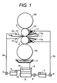
- FIG. 1 A first embodiment of the invention is explained, referring to Fig. 1.
- Fig. 1 is a figure for explaining a cold rolling mill and a cold rolling method of the first embodiment.
- the rolling mill shown in Fig. 1 comprises work rolls 2 for rolling a rolling material 1, reinforcing rolls 2a backing up the work rolls 2, spray headers 10 for lubrication at an inlet side of the rolling material 1, and spray headers 11 for cooling and partition plates 11a at an exit side of the rolling material 1.
- the partition plates 11a are mounted so as to abut the work rolls 2.
- a pan 3 and separating tank 4 are mounted under the work rolls 2 and the reinforcing rolls 2a.
- An oil exclusive use tank 5, an oil conveying pump 6 and an oil conveying pipe line 6a are connected to an upper portion of the separation tank 4, and a first water conveying pump 8, a water exclusive use tank 7, a second water conveying pump 9 and a water conveying pipe line 9a are connected to a lower portion of the separation tank 4 in turn. Further, the oil conveying pipe line 6a and the water conveying pipe line 9a are connected to the spray headers 10 for lubrication oil and the spray headers 11 for cooling, respectively.
- a rolling lubrication oil 12 is supplied between the work rolls 2 and the rolling material 1, that is, to a roll bites from the spray headers 10 for lubrication at the inlet side of the rolling material 1.
- a cooling water 13 is jetted in spray form onto the surfaces of the work rolls 2. The rolling material 1 is contacted with the work rolls cooled, whereby it is avoided that the temperature is raised.
- the above-mentioned lubrication oil 12 and the cooling water 13 are collected in the pan 3 and mixed, and flowed down into the separation tank 4.
- the thickness of the intermediate layer 16 of them changes according to oil composition and other conditions.
- the oil 14 of upper layer after separation is sent to the oil exclusive use tank 5 to be stored temporarily, conveyed to the spray header 10 for lubrication by the oil conveying pump 6 through the oil conveying pipe line 6a, and supplied between the work rolls 2 and the rolling material 1 as rolling lubrication oil 12 again.
- the water 15 of lower layer in the separation tank 4 is sent to the water exclusive use tank 7 by the first water conveying pump 9 to be stored temporarily, sent to the spray headers 11 for cooling by the second water conveying pump 9 through the water conveying pipe line 9a, and is jetted in spray form onto the surfaces of the work rolls 2 as the cooling water 13 again. That is, both of the rolling lubrication oil 12 and the cooling water 13 are recirculated to be used again.
- the cooling water 13 sprayed in spray form from the cooling spray headers 11 is scattered in other direction than the direction of the work rolls 2, but the partition plates 11a abutted to the work rolls 2 prevent scattering to the direction of the rolling material 1, so that the water scattering to at least a side of the rolling material 1 can be prevented. Therefore, water does not remain on the surface of the rolling material 1, inconvenience such as water stain does not occur, whereby slipping of the material at a time of coiling and corrosion of the rolling material 1 during storage after coiling can be avoided, and a high surface quality which is excellent in luster can be attained.
- the rolling lubrication oil 12 mineral oil or synthetic ester, or a substance which includes mixed oil of mineral oil and synthetic ester as a base oil (desirably, straight oil of the concentration of 100%), and does not include, to the utmost, fatty acid, emulsifier, etc. which have good emulsification with water. Since the rolling lubrication oil is formed so as not to include to the utmost an additive promoting emulsification such as fatty acid and emulsifier, the rolling lubrication oil becomes good in separability with water, and a separation process can be practiced rapidly in the separation tank 4.
- an oil which has a mineral oil as a base oil and the viscosity of about 40 cst can be used for cold rolling of stainless steel, in this case, the oil and water are sufficiently separated by the separation tank 4 for about 5 minutes.
- emulsification to a small extent can be allowed, and it can be allowed to include a little amount of the above-mentioned additive such as fatty acid, emulsifier.
- the rolling lubrication oil 12 is supplied from the inlet side of the rolling material 1
- the cooling water 13 is supplied to the surface of the work rolls 2 at the exit side of the rolling material 1
- the cooling water 13 is prevented by the partition plate 11a from being scattered and adhered to the rolling material 1
- adhesion of the cooling water to the surface of the rolling material 1 and penetration of the cooling water into the rolling bite can be avoided as well as rolling lubrication and cooling are effectively carried out, therefore, it can be avoided for the rolling material 1 to slip at time of coiling thereof and to corrode after rolling.
- the rolling lubrication oil 12 and the cooling water 13 are collected in the pan 3 and easily separated by the separation tank 4, and both of them are recirculated to be used again, the lubrication oil 12 and the cooling water 13 can be used without waste, and since the rolling lubrication oil 12 which has a good separability with water is used, separation process in the separation tank 4 can be practiced rapidly.
- cooling water may be mixed with the rolling lubrication oil separated by the separation tank 4, even if the cooling water for roll cooling is mixed with a small amount of oil and becomes emulsion, the cooling ability does not almost change.
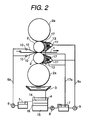
- FIG. 2 A second embodiment of the present invention is explained referring to Fig. 2.
- Fig. 2 the same or similar elements or members are given the same reference numbers as in Fig. 1.
- jackets 17 are provided in stead of the partition plates 11a in Fig. 1, and the cooling water 13 supplied from the exit side of the rolling material 1 to the work rolls 2 is enclosed by the jackets 17.
- the cooling water is recovered from a lower side of each of the jackets 17, and returned into the water exclusive use tank 7 through a recovery pipe line 17a, and sent again to the cooling spray headers 11 by the second water conveying pump 9.
- the cooling water 13 is enclosed and sealed by the jacket 17, scattering and adhesion of the cooling water 13 from the cooling water header 11 to the rolling material 1 are further prevented.
- the construction other than the above-mentioned construction is the same as in the first embodiment.
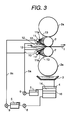
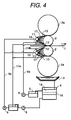
- cooling spray headers 11 and the partition plates as explained in Fig. 1 can be mounted on both of the inlet side and outlet side of the rolling material 1, and the cooling spray headers 11 and the jackets 17 as explained in Fig. 2 also can be mounted on both of the inlet side and the exit side of the rolling material 1.
- the rolling lubrication oil is supplied from the inlet side of the rolling material
- the cooling water is supplied to the surface of the work rolls 2 from at least one side of the inlet side and exit side of the rolling material, and the cooling water is prevented by the scatter preventing means from being scattered and adhered to the rolling material
- roll lubrication and cooling can be effectively carried out, in addition thereto, adhesion of the cooling water to the surface of the rolling material and penetration of the cooling water into the rolling bite can be avoided, therefore, it can be avoided that the rolling material slips at time of coiling thereof and corrodes after rolling.
- the rolling lubrication oil and the cooling water are separated by collecting and separating means and both of them are recirculated to be used again, the lubrication oil and the cooling water can be used without waste. Further since the rolling lubrication oil which has a good separability with water is used, separation process in the tank can be practiced rapidly.
- rolling lubrication and cooling are practiced at a high efficiency, and rolling at a high speed and under high pressure can be effected while maintaining a high surface quality.
- rolling of stainless steel can be done at a high speed and under high pressure although the rolling was limited hitherto.
- reverse rolling or tandem rolling of aluminum which was impossible hitherto becomes possible and productivity can be improved.
- jackets are used as the scatter preventing means, scattering and adhesion of the cooling water to the rolling material can be further prevented and an amount of cooling water mixed into the rolling lubrication oil becomes small and separation thereof by the collecting and separating means becomes very easy.
Landscapes
- Engineering & Computer Science (AREA)
- Mechanical Engineering (AREA)
- Metal Rolling (AREA)
- Details Or Accessories Of Spraying Plant Or Apparatus (AREA)
- Nozzles (AREA)
Applications Claiming Priority (2)
| Application Number | Priority Date | Filing Date | Title |
|---|---|---|---|
| JP8047395A JPH09239429A (ja) | 1996-03-05 | 1996-03-05 | 冷間圧延機および冷間圧延方法 |
| JP47395/96 | 1996-03-05 |
Publications (2)
| Publication Number | Publication Date |
|---|---|
| EP0794023A2 true EP0794023A2 (de) | 1997-09-10 |
| EP0794023A3 EP0794023A3 (de) | 1998-11-11 |
Family
ID=12773934
Family Applications (1)
| Application Number | Title | Priority Date | Filing Date |
|---|---|---|---|
| EP97102976A Withdrawn EP0794023A3 (de) | 1996-03-05 | 1997-02-24 | Kaltwalzwerk und Kaltwalzverfahren |
Country Status (5)
| Country | Link |
|---|---|
| EP (1) | EP0794023A3 (de) |
| JP (1) | JPH09239429A (de) |
| KR (1) | KR970064760A (de) |
| BR (1) | BR9701168A (de) |
| TW (1) | TW318801B (de) |
Cited By (13)
| Publication number | Priority date | Publication date | Assignee | Title |
|---|---|---|---|---|
| WO2005115651A1 (de) * | 2004-05-18 | 2005-12-08 | Sms Demag Ag | Verfahren und vorrichtung zur kühlung und/oder schmierung von walzen und/oder walzgut |
| WO2005120739A1 (de) * | 2004-06-09 | 2005-12-22 | Sms Demag Ag | Verfahren und walzgerüst zum kaltwalzen von metallischen walzgut, insbesondere von walzband, mit düsen für gasförmige oder flüssige behandlungsmedien |
| WO2007025682A1 (de) * | 2005-09-02 | 2007-03-08 | Sms Demag Ag | Verfahren zum schmieren und kühlen von walzen und metallband beim walzen, insbesondere beim kaltwalzen von metallbändern |
| CN100421824C (zh) * | 2005-12-02 | 2008-10-01 | 石川岛播磨重工业株式会社 | 轧制装置 |
| CN103447320A (zh) * | 2012-05-30 | 2013-12-18 | 宝山钢铁股份有限公司 | 冷轧机乳化液浓度快速调整方法 |
| CN104801553A (zh) * | 2015-01-08 | 2015-07-29 | 长沙山水节能研究院有限公司 | 控制轧辊浊循环冷却的系统 |
| WO2015172015A1 (en) * | 2014-05-09 | 2015-11-12 | Novelis Inc. | Hybrid oil and water cooled rolling |
| EP3238843A1 (de) | 2016-04-29 | 2017-11-01 | Primetals Technologies Austria GmbH | Verfahren zum walzen eines walzgutes |
| CN112122348A (zh) * | 2020-08-19 | 2020-12-25 | 吴爱义 | 一种冷轧精细化工艺润滑和冷却系统 |
| CN112292217A (zh) * | 2018-06-13 | 2021-01-29 | 诺维尔里斯公司 | 混合轧机 |
| US10953447B2 (en) | 2018-06-13 | 2021-03-23 | Novelis Inc. | Systems and methods for containing viscous materials in roll processing |
| US11007557B2 (en) * | 2018-06-13 | 2021-05-18 | Novelis Inc. | Systems and methods for removing viscous materials in metal article processing |
| WO2023007222A1 (en) * | 2021-07-28 | 2023-02-02 | Arcelormittal | Device & method for rolling a steel strip |
Families Citing this family (2)
| Publication number | Priority date | Publication date | Assignee | Title |
|---|---|---|---|---|
| CN101829683B (zh) * | 2010-04-27 | 2012-06-13 | 中冶南方工程技术有限公司 | 冷凝水阻断方法 |
| DE102018209854A1 (de) * | 2018-06-19 | 2019-12-19 | Sms Group Gmbh | Emulsionsumlaufanlage |
Citations (5)
| Publication number | Priority date | Publication date | Assignee | Title |
|---|---|---|---|---|
| FR342352A (fr) * | 1903-10-08 | 1904-09-06 | Richard Rees | Procédé et dispositif pour empecher l'échauffement excessif des cylindres métalliques |
| US4272976A (en) * | 1979-06-05 | 1981-06-16 | Mesta Machine Company | Hot strip rolling mill stand |
| NL8204615A (nl) * | 1982-11-29 | 1984-06-18 | Hoogovens Groep Bv | Werkwijze en koelinrichting voor het koelen van walsen van een walserij voor metaalband. |
| US5046347A (en) * | 1989-10-10 | 1991-09-10 | Alcan International Limited | Coolant containment apparatus for rolling mills |
| EP0590682A1 (de) * | 1992-10-02 | 1994-04-06 | Hitachi, Ltd. | Walzwerk mit gekreuzten Arbeitswalzen, Walzanlage und Walzverfahren |
Family Cites Families (4)
| Publication number | Priority date | Publication date | Assignee | Title |
|---|---|---|---|---|
| JPS5930417A (ja) * | 1982-08-10 | 1984-02-18 | Kawasaki Steel Corp | 冷間圧延油の供給方法 |
| JPS60187410A (ja) * | 1984-03-08 | 1985-09-24 | Mitsubishi Metal Corp | 圧延装置 |
| JPS60231508A (ja) * | 1984-04-27 | 1985-11-18 | Kawasaki Steel Corp | 圧延ロ−ルの冷却装置 |
| JPH0839112A (ja) * | 1994-08-01 | 1996-02-13 | Ishikawajima Harima Heavy Ind Co Ltd | 圧延ロールの冷却装置 |
-
1996
- 1996-03-05 JP JP8047395A patent/JPH09239429A/ja active Pending
-
1997
- 1997-02-24 EP EP97102976A patent/EP0794023A3/de not_active Withdrawn
- 1997-02-25 TW TW086102273A patent/TW318801B/zh active
- 1997-03-04 BR BR9701168A patent/BR9701168A/pt not_active Application Discontinuation
- 1997-03-04 KR KR1019970006994A patent/KR970064760A/ko not_active Application Discontinuation
Patent Citations (5)
| Publication number | Priority date | Publication date | Assignee | Title |
|---|---|---|---|---|
| FR342352A (fr) * | 1903-10-08 | 1904-09-06 | Richard Rees | Procédé et dispositif pour empecher l'échauffement excessif des cylindres métalliques |
| US4272976A (en) * | 1979-06-05 | 1981-06-16 | Mesta Machine Company | Hot strip rolling mill stand |
| NL8204615A (nl) * | 1982-11-29 | 1984-06-18 | Hoogovens Groep Bv | Werkwijze en koelinrichting voor het koelen van walsen van een walserij voor metaalband. |
| US5046347A (en) * | 1989-10-10 | 1991-09-10 | Alcan International Limited | Coolant containment apparatus for rolling mills |
| EP0590682A1 (de) * | 1992-10-02 | 1994-04-06 | Hitachi, Ltd. | Walzwerk mit gekreuzten Arbeitswalzen, Walzanlage und Walzverfahren |
Non-Patent Citations (4)
| Title |
|---|
| PATENT ABSTRACTS OF JAPAN vol. 008, no. 128 (M-302), 14 June 1984 -& JP 59 030417 A (KAWASAKI SEITETSU KK), 18 February 1984 * |
| PATENT ABSTRACTS OF JAPAN vol. 010, no. 029 (M-451), 5 February 1986 -& JP 60 187410 A (MITSUBISHI KINZOKU KK), 24 September 1985 * |
| PATENT ABSTRACTS OF JAPAN vol. 010, no. 096 (M-469), 12 April 1986 -& JP 60 231508 A (KAWASAKI SEITETSU KK), 18 November 1985 * |
| PATENT ABSTRACTS OF JAPAN vol. 096, no. 006, 28 June 1996 -& JP 08 039112 A (ISHIKAWAJIMA HARIMA HEAVY IND CO LTD), 13 February 1996 * |
Cited By (27)
| Publication number | Priority date | Publication date | Assignee | Title |
|---|---|---|---|---|
| US7690235B2 (en) | 2004-05-18 | 2010-04-06 | Sms Demag Ag | Method of and device for cooling and or lubrication |
| WO2005115651A1 (de) * | 2004-05-18 | 2005-12-08 | Sms Demag Ag | Verfahren und vorrichtung zur kühlung und/oder schmierung von walzen und/oder walzgut |
| WO2005120739A1 (de) * | 2004-06-09 | 2005-12-22 | Sms Demag Ag | Verfahren und walzgerüst zum kaltwalzen von metallischen walzgut, insbesondere von walzband, mit düsen für gasförmige oder flüssige behandlungsmedien |
| US7472574B2 (en) | 2004-06-09 | 2009-01-06 | Hartmut Pawelski | Method of and rolling mill stand for cold rolling mill stand for cold rolling of metallic rolling stock in particular rolling strip with nozzles for gaseous or liquid treatment media |
| WO2007025682A1 (de) * | 2005-09-02 | 2007-03-08 | Sms Demag Ag | Verfahren zum schmieren und kühlen von walzen und metallband beim walzen, insbesondere beim kaltwalzen von metallbändern |
| AU2006286797B2 (en) * | 2005-09-02 | 2010-11-25 | Sms Siemag Aktiengesellschaft | Method for lubricating and cooling rollers and metal strips on rolling in particular on cold rolling of metal strips |
| US8001820B2 (en) | 2005-09-02 | 2011-08-23 | Sms Siemag Aktiengesellschaft | Method for lubricating and cooling rollers and metal strips on rolling in particular on cold rolling of metal strips |
| CN100421824C (zh) * | 2005-12-02 | 2008-10-01 | 石川岛播磨重工业株式会社 | 轧制装置 |
| CN103447320B (zh) * | 2012-05-30 | 2015-08-26 | 宝山钢铁股份有限公司 | 冷轧机乳化液浓度快速调整方法 |
| CN103447320A (zh) * | 2012-05-30 | 2013-12-18 | 宝山钢铁股份有限公司 | 冷轧机乳化液浓度快速调整方法 |
| CN106413929A (zh) * | 2014-05-09 | 2017-02-15 | 诺维尔里斯公司 | 混合油冷和水冷轧制 |
| EP3140057B1 (de) | 2014-05-09 | 2019-09-04 | Novelis, Inc. | Hybrid gekühltes walzen mittels öl und wasser |
| WO2015172015A1 (en) * | 2014-05-09 | 2015-11-12 | Novelis Inc. | Hybrid oil and water cooled rolling |
| CN106413929B (zh) * | 2014-05-09 | 2021-08-10 | 诺维尔里斯公司 | 混合油冷和水冷轧制 |
| US9925575B2 (en) | 2014-05-09 | 2018-03-27 | Novelis Inc. | Hybrid oil and water cooled rolling |
| CN104801553A (zh) * | 2015-01-08 | 2015-07-29 | 长沙山水节能研究院有限公司 | 控制轧辊浊循环冷却的系统 |
| CN104801553B (zh) * | 2015-01-08 | 2017-02-22 | 长沙山水节能研究院有限公司 | 控制轧辊浊循环冷却的系统 |
| US11161161B2 (en) | 2016-04-29 | 2021-11-02 | Primetals Technologies Austria GmbH | Method for rolling a product to be rolled |
| WO2017186910A1 (de) | 2016-04-29 | 2017-11-02 | Primetals Technologies Austria GmbH | Verfahren zum walzen eines walzgutes |
| EP3238843A1 (de) | 2016-04-29 | 2017-11-01 | Primetals Technologies Austria GmbH | Verfahren zum walzen eines walzgutes |
| CN112292217A (zh) * | 2018-06-13 | 2021-01-29 | 诺维尔里斯公司 | 混合轧机 |
| US10953447B2 (en) | 2018-06-13 | 2021-03-23 | Novelis Inc. | Systems and methods for containing viscous materials in roll processing |
| US11007557B2 (en) * | 2018-06-13 | 2021-05-18 | Novelis Inc. | Systems and methods for removing viscous materials in metal article processing |
| RU2761304C1 (ru) * | 2018-06-13 | 2021-12-07 | Новелис Инк. | Системы и способы удаления вязких материалов при обработке металлических изделий |
| CN112122348A (zh) * | 2020-08-19 | 2020-12-25 | 吴爱义 | 一种冷轧精细化工艺润滑和冷却系统 |
| WO2023007222A1 (en) * | 2021-07-28 | 2023-02-02 | Arcelormittal | Device & method for rolling a steel strip |
| WO2023007378A1 (en) * | 2021-07-28 | 2023-02-02 | Arcelormittal | Device & method for rolling a steel strip |
Also Published As
| Publication number | Publication date |
|---|---|
| BR9701168A (pt) | 1998-12-15 |
| EP0794023A3 (de) | 1998-11-11 |
| JPH09239429A (ja) | 1997-09-16 |
| TW318801B (de) | 1997-11-01 |
| KR970064760A (ko) | 1997-10-13 |
Similar Documents
| Publication | Publication Date | Title |
|---|---|---|
| EP0794023A2 (de) | Kaltwalzwerk und Kaltwalzverfahren | |
| AU2002321114B2 (en) | Method and device for cooling and lubricating rollers on a rolling stand | |
| RU2352414C1 (ru) | Способ подачи смазочного масла при холодной прокатке | |
| JPH02151309A (ja) | ロールおよび被圧延材を冷却および潤滑するための方法およびこれを実施するためのエマルジョン循環装置 | |
| KR20020008175A (ko) | 냉간압연의 압연유 공급방법 | |
| JP4905056B2 (ja) | 金属板の冷間圧延方法及び冷間タンデム圧延機 | |
| JP4715564B2 (ja) | 冷間圧延方法 | |
| JPS585731B2 (ja) | 冷間圧延機における給油方法 | |
| JP5104389B2 (ja) | 冷間圧延ロールの冷却方法および鋼板の冷間圧延方法ならびに冷間圧延ロールの冷却装置 | |
| JP2007253178A (ja) | 冷間圧延方法 | |
| JPH11129002A (ja) | 熱間仕上圧延方法 | |
| JP2005193242A (ja) | 金属板の冷間タンデム圧延方法および冷間タンデム圧延機 | |
| EP3446800B1 (de) | Einrichtung und verfahren zum kaltwalzen eines metallstreifens | |
| JP2008194721A (ja) | 金属板の冷間圧延方法 | |
| JP4830888B2 (ja) | 金属板の冷間圧延方法および冷間タンデム圧延機 | |
| JPH11290903A (ja) | 熱間圧延方法 | |
| JP3785769B2 (ja) | ステンレス鋼板の冷間圧延方法 | |
| JP3286159B2 (ja) | 熱間潤滑圧延方法 | |
| JP4191838B2 (ja) | 冷間タンデム圧延方法 | |
| JP2002224731A (ja) | 冷間圧延における潤滑油供給方法 | |
| JPH057081B2 (de) | ||
| JPH0810427Y2 (ja) | 圧延油供給装置 | |
| JPS6018219A (ja) | 冷間圧延潤滑方法 | |
| JPS626716A (ja) | 温間圧延における圧延油供給方法 | |
| JPH02160105A (ja) | 熱間高潤滑圧延方法並びにそのための設備 |
Legal Events
| Date | Code | Title | Description |
|---|---|---|---|
| PUAI | Public reference made under article 153(3) epc to a published international application that has entered the european phase |
Free format text: ORIGINAL CODE: 0009012 |
|
| AK | Designated contracting states |
Kind code of ref document: A2 Designated state(s): DE GB |
|
| PUAL | Search report despatched |
Free format text: ORIGINAL CODE: 0009013 |
|
| AK | Designated contracting states |
Kind code of ref document: A3 Designated state(s): DE GB |
|
| 17P | Request for examination filed |
Effective date: 19981015 |
|
| STAA | Information on the status of an ep patent application or granted ep patent |
Free format text: STATUS: THE APPLICATION HAS BEEN WITHDRAWN |
|
| 18W | Application withdrawn |
Withdrawal date: 19981223 |