EP0790604A2 - Dispositif de lecture pour disques optiques - Google Patents
Dispositif de lecture pour disques optiques Download PDFInfo
- Publication number
- EP0790604A2 EP0790604A2 EP97102352A EP97102352A EP0790604A2 EP 0790604 A2 EP0790604 A2 EP 0790604A2 EP 97102352 A EP97102352 A EP 97102352A EP 97102352 A EP97102352 A EP 97102352A EP 0790604 A2 EP0790604 A2 EP 0790604A2
- Authority
- EP
- European Patent Office
- Prior art keywords
- disk
- optical
- signal
- reproduction device
- pick
- Prior art date
- Legal status (The legal status is an assumption and is not a legal conclusion. Google has not performed a legal analysis and makes no representation as to the accuracy of the status listed.)
- Granted
Links
Images


Classifications
-
- G—PHYSICS
- G11—INFORMATION STORAGE
- G11B—INFORMATION STORAGE BASED ON RELATIVE MOVEMENT BETWEEN RECORD CARRIER AND TRANSDUCER
- G11B7/00—Recording or reproducing by optical means, e.g. recording using a thermal beam of optical radiation by modifying optical properties or the physical structure, reproducing using an optical beam at lower power by sensing optical properties; Record carriers therefor
- G11B7/12—Heads, e.g. forming of the optical beam spot or modulation of the optical beam
- G11B7/135—Means for guiding the beam from the source to the record carrier or from the record carrier to the detector
- G11B7/1381—Non-lens elements for altering the properties of the beam, e.g. knife edges, slits, filters or stops
-
- G—PHYSICS
- G11—INFORMATION STORAGE
- G11B—INFORMATION STORAGE BASED ON RELATIVE MOVEMENT BETWEEN RECORD CARRIER AND TRANSDUCER
- G11B19/00—Driving, starting, stopping record carriers not specifically of filamentary or web form, or of supports therefor; Control thereof; Control of operating function ; Driving both disc and head
- G11B19/02—Control of operating function, e.g. switching from recording to reproducing
- G11B19/12—Control of operating function, e.g. switching from recording to reproducing by sensing distinguishing features of or on records, e.g. diameter end mark
-
- G—PHYSICS
- G11—INFORMATION STORAGE
- G11B—INFORMATION STORAGE BASED ON RELATIVE MOVEMENT BETWEEN RECORD CARRIER AND TRANSDUCER
- G11B7/00—Recording or reproducing by optical means, e.g. recording using a thermal beam of optical radiation by modifying optical properties or the physical structure, reproducing using an optical beam at lower power by sensing optical properties; Record carriers therefor
- G11B7/002—Recording, reproducing or erasing systems characterised by the shape or form of the carrier
- G11B7/0037—Recording, reproducing or erasing systems characterised by the shape or form of the carrier with discs
-
- G—PHYSICS
- G11—INFORMATION STORAGE
- G11B—INFORMATION STORAGE BASED ON RELATIVE MOVEMENT BETWEEN RECORD CARRIER AND TRANSDUCER
- G11B7/00—Recording or reproducing by optical means, e.g. recording using a thermal beam of optical radiation by modifying optical properties or the physical structure, reproducing using an optical beam at lower power by sensing optical properties; Record carriers therefor
- G11B7/08—Disposition or mounting of heads or light sources relatively to record carriers
- G11B7/09—Disposition or mounting of heads or light sources relatively to record carriers with provision for moving the light beam or focus plane for the purpose of maintaining alignment of the light beam relative to the record carrier during transducing operation, e.g. to compensate for surface irregularities of the latter or for track following
- G11B7/0901—Disposition or mounting of heads or light sources relatively to record carriers with provision for moving the light beam or focus plane for the purpose of maintaining alignment of the light beam relative to the record carrier during transducing operation, e.g. to compensate for surface irregularities of the latter or for track following for track following only
- G11B7/0903—Multi-beam tracking systems
-
- G—PHYSICS
- G11—INFORMATION STORAGE
- G11B—INFORMATION STORAGE BASED ON RELATIVE MOVEMENT BETWEEN RECORD CARRIER AND TRANSDUCER
- G11B7/00—Recording or reproducing by optical means, e.g. recording using a thermal beam of optical radiation by modifying optical properties or the physical structure, reproducing using an optical beam at lower power by sensing optical properties; Record carriers therefor
- G11B7/08—Disposition or mounting of heads or light sources relatively to record carriers
- G11B7/09—Disposition or mounting of heads or light sources relatively to record carriers with provision for moving the light beam or focus plane for the purpose of maintaining alignment of the light beam relative to the record carrier during transducing operation, e.g. to compensate for surface irregularities of the latter or for track following
- G11B7/0925—Electromechanical actuators for lens positioning
- G11B7/093—Electromechanical actuators for lens positioning for focusing and tracking
-
- G—PHYSICS
- G11—INFORMATION STORAGE
- G11B—INFORMATION STORAGE BASED ON RELATIVE MOVEMENT BETWEEN RECORD CARRIER AND TRANSDUCER
- G11B7/00—Recording or reproducing by optical means, e.g. recording using a thermal beam of optical radiation by modifying optical properties or the physical structure, reproducing using an optical beam at lower power by sensing optical properties; Record carriers therefor
- G11B7/12—Heads, e.g. forming of the optical beam spot or modulation of the optical beam
- G11B7/125—Optical beam sources therefor, e.g. laser control circuitry specially adapted for optical storage devices; Modulators, e.g. means for controlling the size or intensity of optical spots or optical traces
- G11B7/127—Lasers; Multiple laser arrays
- G11B7/1275—Two or more lasers having different wavelengths
-
- G—PHYSICS
- G11—INFORMATION STORAGE
- G11B—INFORMATION STORAGE BASED ON RELATIVE MOVEMENT BETWEEN RECORD CARRIER AND TRANSDUCER
- G11B7/00—Recording or reproducing by optical means, e.g. recording using a thermal beam of optical radiation by modifying optical properties or the physical structure, reproducing using an optical beam at lower power by sensing optical properties; Record carriers therefor
- G11B7/12—Heads, e.g. forming of the optical beam spot or modulation of the optical beam
- G11B7/13—Optical detectors therefor
- G11B7/131—Arrangement of detectors in a multiple array
-
- G—PHYSICS
- G11—INFORMATION STORAGE
- G11B—INFORMATION STORAGE BASED ON RELATIVE MOVEMENT BETWEEN RECORD CARRIER AND TRANSDUCER
- G11B7/00—Recording or reproducing by optical means, e.g. recording using a thermal beam of optical radiation by modifying optical properties or the physical structure, reproducing using an optical beam at lower power by sensing optical properties; Record carriers therefor
- G11B7/12—Heads, e.g. forming of the optical beam spot or modulation of the optical beam
- G11B7/135—Means for guiding the beam from the source to the record carrier or from the record carrier to the detector
- G11B7/1372—Lenses
-
- G—PHYSICS
- G11—INFORMATION STORAGE
- G11B—INFORMATION STORAGE BASED ON RELATIVE MOVEMENT BETWEEN RECORD CARRIER AND TRANSDUCER
- G11B7/00—Recording or reproducing by optical means, e.g. recording using a thermal beam of optical radiation by modifying optical properties or the physical structure, reproducing using an optical beam at lower power by sensing optical properties; Record carriers therefor
- G11B7/12—Heads, e.g. forming of the optical beam spot or modulation of the optical beam
- G11B7/135—Means for guiding the beam from the source to the record carrier or from the record carrier to the detector
- G11B7/139—Numerical aperture control means
-
- G—PHYSICS
- G11—INFORMATION STORAGE
- G11B—INFORMATION STORAGE BASED ON RELATIVE MOVEMENT BETWEEN RECORD CARRIER AND TRANSDUCER
- G11B7/00—Recording or reproducing by optical means, e.g. recording using a thermal beam of optical radiation by modifying optical properties or the physical structure, reproducing using an optical beam at lower power by sensing optical properties; Record carriers therefor
- G11B2007/0003—Recording, reproducing or erasing systems characterised by the structure or type of the carrier
- G11B2007/0006—Recording, reproducing or erasing systems characterised by the structure or type of the carrier adapted for scanning different types of carrier, e.g. CD & DVD
-
- G—PHYSICS
- G11—INFORMATION STORAGE
- G11B—INFORMATION STORAGE BASED ON RELATIVE MOVEMENT BETWEEN RECORD CARRIER AND TRANSDUCER
- G11B7/00—Recording or reproducing by optical means, e.g. recording using a thermal beam of optical radiation by modifying optical properties or the physical structure, reproducing using an optical beam at lower power by sensing optical properties; Record carriers therefor
- G11B2007/0003—Recording, reproducing or erasing systems characterised by the structure or type of the carrier
- G11B2007/0009—Recording, reproducing or erasing systems characterised by the structure or type of the carrier for carriers having data stored in three dimensions, e.g. volume storage
- G11B2007/0013—Recording, reproducing or erasing systems characterised by the structure or type of the carrier for carriers having data stored in three dimensions, e.g. volume storage for carriers having multiple discrete layers
-
- G—PHYSICS
- G11—INFORMATION STORAGE
- G11B—INFORMATION STORAGE BASED ON RELATIVE MOVEMENT BETWEEN RECORD CARRIER AND TRANSDUCER
- G11B20/00—Signal processing not specific to the method of recording or reproducing; Circuits therefor
- G11B20/00007—Time or data compression or expansion
- G11B2020/00014—Time or data compression or expansion the compressed signal being an audio signal
- G11B2020/00057—MPEG-1 or MPEG-2 audio layer III [MP3]
-
- G—PHYSICS
- G11—INFORMATION STORAGE
- G11B—INFORMATION STORAGE BASED ON RELATIVE MOVEMENT BETWEEN RECORD CARRIER AND TRANSDUCER
- G11B20/00—Signal processing not specific to the method of recording or reproducing; Circuits therefor
- G11B20/10—Digital recording or reproducing
- G11B2020/1087—Digital recording or reproducing wherein a selection is made among at least two alternative ways of processing
- G11B2020/10879—Digital recording or reproducing wherein a selection is made among at least two alternative ways of processing the kind of record carrier being the selection criterion
-
- G—PHYSICS
- G11—INFORMATION STORAGE
- G11B—INFORMATION STORAGE BASED ON RELATIVE MOVEMENT BETWEEN RECORD CARRIER AND TRANSDUCER
- G11B2220/00—Record carriers by type
- G11B2220/20—Disc-shaped record carriers
- G11B2220/23—Disc-shaped record carriers characterised in that the disc has a specific layer structure
- G11B2220/235—Multilayer discs, i.e. multiple recording layers accessed from the same side
-
- G—PHYSICS
- G11—INFORMATION STORAGE
- G11B—INFORMATION STORAGE BASED ON RELATIVE MOVEMENT BETWEEN RECORD CARRIER AND TRANSDUCER
- G11B7/00—Recording or reproducing by optical means, e.g. recording using a thermal beam of optical radiation by modifying optical properties or the physical structure, reproducing using an optical beam at lower power by sensing optical properties; Record carriers therefor
- G11B7/08—Disposition or mounting of heads or light sources relatively to record carriers
- G11B7/09—Disposition or mounting of heads or light sources relatively to record carriers with provision for moving the light beam or focus plane for the purpose of maintaining alignment of the light beam relative to the record carrier during transducing operation, e.g. to compensate for surface irregularities of the latter or for track following
- G11B7/0941—Methods and circuits for servo gain or phase compensation during operation
Definitions
- This invention relates to a reproduction device for optical disks, more specifically, a device for conducting appropriate reproduction and recording according to the kind of an optical disk by relating a plurality of optical systems having different beam spot sizes or different wavelengths and a signal processing system having a plurality of signal processing characteristics corresponding to the above-mentioned plurality of optical systems.
- an object of the invention is to provide a reproduction device for optical disks capable of providing an appropriate signal processing by switching the signal processing side characteristics of a read-out signal according to switching of the characteristics of the optical system.
- Another object of the invention is to provide a reproduction device for optical disks comprising a plurality of optical systems and a signal processing system having a plurality of signal processing characteristics corresponding to the above-mentioned plurality of the optical systems for conducting appropriate reproduction and recording according to the kind of an optical disk by corresponding one of the optical systems and one of the signal processing characteristics.
- Still another object of the invention is to provide a reproduction device for optical disks capable of distinguishing different kinds of optical disks precisely.
- the invention relates to a reproduction device for optical disks to reproduce signals recorded in a plural of disks via an optical pick-up, comprising a numerical aperture changing means to change the numerical aperture of a beam outputted from the above-mentioned optical pick-up according to the disk to be reproduced and a signal processing system changing means to change the characteristics of a signal processing system connected to the later stage of the above-mentioned pick-up subsequent to the change of the numerical aperture of the beam by the above-mentioned numerical aperture changing means according to the disk to be reproduced.
- the invention comprises a plurality of optical systems having different pick-up characteristics and a means to construct a signal processing system corresponding to one selected from the plurality of the optical systems by collecting the selected signal .
- a signal reproduction route appropriate for each type of optical disks or the type of the signal recorded in the disk can be constructed.
- the above-mentioned plurality of optical systems of the invention are optical systems having different beam spot sizes or different wavelengths.
- a three-beam system and an one-beam system can be switched so as to switch the three-beam system used in reproducing a disk with a first size pit and the one-beam system used in reproducing a disk with a second size pit, which is smaller than the first size pit.
- An optical pick-up device of the invention comprises a plurality of optical systems having different beam spot sizes or wavelengths, a switching means facing to an optical disk mounted with one of the above-mentioned plurality of optical systems, a detecting means to detect a reflected light of a beam irradiated to the above-mentioned optical disk, a focus adjusting mechanism for the above-mentioned optical disk, and a tracking adjusting mechanism for the above-mentioned optical disk. Further, the signal processing portion capable of switching the processing characteristics according to the kind of the optical disk reproduces the signal recorded in the above-mentioned optical disk utilizing the signal detected with the above-mentioned detecting means.
- a focus servo means capable of switching the servo characteristics according to the kind of the optical disk generates a focus error signal utilizing the signal detected with the above-mentioned detecting means for feeding back to the above-mentioned focus adjusting mechanism.
- a tracking servo means capable of switching the servo characteristics according to the kind of the optical disk generates a tracking error signal utilizing the signal detected with the above-mentioned detecting means for feeding back to the above-mentioned tracking adjusting mechanism.
- a system controlling means comprises an optical system setting means to allow the above-mentioned switching means to select an optional optical system suitable for an optional optical disk as the optical system to be used, a system setting means to switch the above-mentioned signal processing portion, focus servo means and tracking servo means to have processing characteristics and servo characteristics corresponding to the above-mentioned optional optical disk, and the above-mentioned distinguishing means of the kind of the optical disk.
- suitable optical systems or reproduction processing characteristics can be set for reading out the recorded signals according to various kinds of optical disks.
- FIG. 1 includes cross-sectional views illustrating principles of different kinds of optical disks.
- FIG. 1A shows a conventional compact disk (so-called CD) for music use, of which thickness is ruled to be 1.2 mm by a regulation.
- FIG. 1B shows an optical disk wherein a high density recording is achieved with image codes and audio codes processed with data compression, including a super high density optical digital video disk capable of recording and reproduction (hereinafter abbreviated as DVD). Therefore, DVDs include DVD-ROMs only for reproduction and DVD-RAMs also capable of recording.
- FIG. 1B shows one having one-layer structure in the reading and recording surface
- FIG. 1C shows a DVD-ROM having two-layer structure with two pieces attached. Either type of disks is ruled to have an 1.2 mm entire thickness and a 0.6 mm substrate thickness by regulation. Besides, both CDs and DVDs are ruled to have a diameter of 12 cm/8 cm respectively.
- FIG. 2 include enlarged recording surfaces of the above-mentioned optical disks shown from the back side.
- FIG. 2A shows a structure of the recording surface of a CD.
- FIG. 2B shows a structure of the recording surface of a DVD-ROM.
- FIG. 2C shows a structure of the recording surface of a DVD-RAM.
- the disk substrate thickness, pit width and track width are also shown in these Figures.
- optical disks have different track pitches or different recording formats.
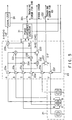
- FIG. 3 illustrates a reproduction device utilizing the invention.
- Numeral 11 denotes an optical disk to be rotated with a disk motor 12.
- Numeral 21 denotes a light pick-up device to be controlled and moved with respect to the radial direction of the disk with a feed motor 22.
- the light pick-up device 21 comprises optical systems of which numerical aperture of a beam can be changed so as to irradiate both a beam for CD and a beam for DVD. Therefore, the optical systems for the light pick-up device 21 can be switched according to the optical disk to be reproduced or recorded.
- CDs and DVDs differ in terms of the substrate thickness, pit width and track width, an appropriate beam spot needs to be prepared in order to obtain effective reflected light signal characteristics.
- DVDs require a smaller beam spot and have a shallower pit depth compared with CDs, and thus a beam spot suitable therefor is needed. Switching of beam spots may be conducted by switching beams having different wavelengths.
- the optical pick-up device 21 comprises at least the below-mentioned means. Namely, a plurality of optical systems having beam spots of different sizes or different wavelengths, a switching mechanism for selecting one of the plurality of the optical systems and arranging the selected optical system facing to the optical disk mounted on the device, a light detecting element portion for detecting the reflected light of a beam irradiated to the optical disk, a focus adjusting mechanism for the optical disk, and a tracking adjusting mechanism for the above-mentioned optical disk.
- a plurality of optical systems having different wavelengths may have wavelengths of 650 nm, 780 nm and 685 nm.
- a detected signal obtained from a plurality of photo diodes comprising the light detecting element portion of the light pick-up device 21 is inputted to a preamplifier 23.
- a synthesized signal HF of the output (A, B, C, D) of a four-split photo diode, a focus error signal, an (A+C) signal and, a (B+D) signal from the detected signals of the four-split photo diode, and an (E+F) signal, which serves as a tracking error signal for CD can be obtained.
- the synthesized signal HF is wave-form equalized via an equalizer and inputted to a DVD/CD signal processing portion 25.
- the DVD/CD signal processing portion 25 can be switched between the DVD processing mode and the CD processing mode according to a controlling signal from a system controlling portion 100 later described.
- Equalizers and signal processing portions may be prepared each for DVDs and for CDs.
- an appropriate gain setting signal may be provided to other driving amplifier in the servo system from the controlling portion 100 according to the kind of the disk.
- a sub beam/main beam system is adopted in reproducing a CD utilizing detected signals A to F and a one beam system (main beam system) is adopted in reproducing a DVD utilizing detected signals A to D.
- the sub beam/main beam system is, specifically, a system including both a three beam system and a one beam system.
- the three beam system is, as later described, a system wherein a reflected light is picked up by at least a four-split photo diode and a diode arranged in the vicinity of the diode to utilize outputs A to F thereof.
- the one beam system is a system wherein a reflected light is picked up by a photo diode to utilize outputs A to D thereof.
- the focus error signal is inputted to an S-letter level detector 26B through a filter 26A for reducing noise and also to a compensation amplifier 27.
- the output from the compensation amplifier 27 is inputted to a driving circuit 28 to become a focus controlling signal, and then provided to a focus controlling mechanism of the light pick-up device 21.
- the system controlling portion 100 selects and switches to an optical system, at the same time, or subsequently, characteristics of the servo system and the signal processing system connected to the later stage or the route itself will be switched automatically.
- FIG. 4 illustrates the change of a focus error signal according to the state of focusing.
- the change is detected at an S-letter level detector 26B.
- a focus error signal is generated from the detected signal of the main beam in the embodiment, it can be generated from the detected signal of the sub beam because detected signals of a sub beam have a similar S-letter characteristics according to the state of focusing even though they differ from those of the main beam in level.
- the sub beam detector may be constituted of a four-split photo diode.
- the detected level information detected here is inputted to the system controlling portion 100.
- the system controlling portion 100 makes judgment of the kinds of optical disks utilizing the S-letter detection level as later described.
- an (A+B) signal, a (B+D) signal and an (E-F) signal detected by a photo diode of a light pick-up device 21 are obtained.
- the (A+C) signal and the (B+D) signal are inputted to a phase difference detector 31.
- the phase difference detector 31 obtains a tracking error signal for DVD by detecting the difference between the (A+B) signal and the (B+D) signal.
- the tracking error signal for DVD is provided to one side of a switch 32.
- the (E-F) signal is used as a tracking error signal for CD, and the signal is provided to the other side of the switch 32.
- the switch 32 is switched according to the system setting mode of the system controlling portion 100 and the disk kind judging signal, that is, if a CD is placed as the disk 11, a tracking error signal for CD is selected, and if a DVD is placed, a tracking error signal for DVD is selected.
- a signal outputted from the switch is inputted to a compensation amplifier 33.
- An output from the compensation amplifier 33 becomes a tracking controlling signal via a driving circuit 34, and then provided to a tracking controlling mechanism of the light pick-up device 21. Furthermore, a signal with a lot of controlling amount is provided to a feed motor 22 via a driving circuit 35.
- the frequency and the phase of a reproduced signal is detected and a controlling information included in the reproduced signal is demodulated, and a disk motor control signal is generated according to the controlling information such as a synchronizing signal.
- a servo loop is formed by providing the disk motor control signal to a disk motor 12 via a driving circuit 36.
- the system controlling portion 100 provides controlling signals to the equalizer 24 and the DVD/CD signal processing portion 25.
- the controlling signals are for switching equalizing characteristics and a processing clock or the operation state of the equalizer 24 and the DVD/CD signal processing portion 25 according to the setting of the CD mode or the DVD mode. Further, the system controlling portion 100 can switch and set response characteristic and operation mode of each servo system.
- controlling signals are provided to the switch 32.
- the controlling signals control the switch 32 to pick up a tracking error signal from the phase difference detector 31 in the DVD mode and to pick up an (E-F) signal as a tracking error signal in the CD mode.
- controlling signals are provided also to the compensation amplifier 33 in the tracking servo loop.
- the controlling signals are for switching the loop characteristics of the tracking servo loop, and thus specifically speaking, are gain switching signals.
- controlling signals are provided also for the compensation amplifier 27 of the focus servo loop.
- the controlling signals also are gain switching signals for switching loop characteristics of the focus servo loop.
- system controlling portion 100 can forcibly stop or move the servo operation instead of automatic operation when the disk judgment is conducted.
- FIG. 5 alignment of photo diodes A to F and the inside of the preamplifier 23 comprising the light detecting portion of the light pick-up device 21 are shown. Output of each of the photo diodes A to F are introduced to buffer amplifiers 23a to 23f respectively.
- the A to F signals outputted from the buffer amplifier 23a to 23f are calculated as mentioned below.
- An adding device 231 generates (A+B) signals and an adding device 232 generates (C+D) signals.
- a subtracting device 233 generates (A+B) - (C+D) signals utilizing the (A+C) signals from the adding device 231 and the (C+D) signals from the adding device 232.
- the (A+B) - (C+D) signals are used as focus error signals.
- An adding device 234 generates (A+C) signals, and an adding device 235 generates (B+D) signals.
- the (A+C) signals and the (B+D) signals are inputted to a phase difference detector 31.
- the output from the phase difference detector 31 is used as a tracking error signal for DVD. That is, when the device is on the DVD mode, a switch 321 is controlled to turn on.
- an (E-F) signal obtained based on a detected signal of the sub beam is ignored with a switch 322 turned off.
- the (A+C) signals and the (B+D) signals are inputted also to an adding device 236.
- the adding device 236 generates an (A+B+C+D) signal (hereinafter abbreviated as an HF signal).
- E signals and F signals are inputted to an adding device 237. From the adding device 237, (E-F) signals can be obtained.
- the (E-F) signals are used as a tracking error signal for CD. That is, when the device is on the CD mode, the switch 322 is controlled to turn on.
- one of a plurality of optical systems is set based on the control of the system controlling portion 100.
- the system controlling portion 100 recognizes that and automatically switches the other related signal processing systems to be the CD mode accordingly.
- Signal processing system include a DVD/CD signal processing portion 25 and a servo system.
- the system controlling portion 100 recognizes that and automatically switches the other related signal processing systems to be the DVD mode accordingly.
- reproduction and recording devices need to have a plurality of optical systems to correspond to different kinds of disks, and a signal processing system capable of switching a plurality of characteristics, or signal processing systems corresponding to each optical system.
- a user can input the kind of the disk in advance from the operating portion of the reproduction and recording device.
- the disk kind information is inputted to the system controlling portion 100 to be acknowledged. Based on the acknowledged information, as mentioned above, an optical system and a signal processing system corresponding to the kind of the disk are set by the system controlling portion 100.
- an automatic judgment function works for judging the kind of the disk.
- the information obtained by the automatic judgment function is acknowledged by the system controlling portion 100. Based on the acknowledged information, as mentioned above, an optical system and a signal processing system corresponding to the kind of the disk are set by the system controlling portion 100.
- the automatic judgment device functions even after a user makes judgment of the kind of the disk and inputs an initial system setting state by the manual operation. In such a case, the device would correct a possible misjudgment of the user on the kind of the disk.
- the device is automatically set to be a certain initial state when a disk is placed, or set to be the state of the preceding use.
- a signal processing system include the below-mentioned circuits.
- a reproduced signal processing portion for demodulating and reproducing a recorded signal from an optical disk utilizing a pick-up signal from a pick-up device, a focus servo circuit, which is a servo system for conducting the focus control of the optical system of the pick-up device utilizing a pick-up signal from the pick-up device and capable of switching characteristics, and a tracking servo circuit, which is a servo system for conducting the tracking control of an optical system of the pick-up device utilizing a pick-up signal and capable of switching characteristics.
- An optical system (lens) of the light pick-up device 21 is set to be either one. That is, the light-pick-up device 21 inevitably set to be either mode (CD mode or DVD mode) in the initial state according to a switching signal from the system controlling portion 100. At that time, a focus servo and a tracking servo system are also set to be the mode corresponding to the initial setting mode of the optical system by the system controlling portion 100. Similarly, the signal processing portion 25 is set to be the mode corresponding to the initial setting mode of the optical system.
- One-layer disks of CD or DVD and two-layer disks of DVD-ROM or DVD-RAM differ in terms of a refractive index of an irradiated light beam.
- the phenomenon that refractive indexes of light beams differ according to the kind of the disk is utilized effectively.
- a refractive index of a one-layer disk of CD or DVD is about 60 to 70 %, two-layer disk of DVD-ROM is 25 to 30 %, and one-layer disk of DVD-RAM is 20 % or less.
- judgment on whether it is a two-layer disk (a two-layer disk of DVD-ROM) or a one-layer disk (a one-layer disk of CD or DVD) can be made from the number of focal planes learned from a focus signal obtained by first arranging a lens at a position far from a disk and gradually moving the lens toward the disk.
- the disk may be stopped without rotation or may rotate for less than half turn or at a constant rate (slow rotation).
- a rotation servo system has a forcible rotation control rather than automatic drive since with the servo system on, rotation may be rampant.
- a rotation rate of a constant rotation is preferably the rate of the inner periphery of CLV or the maximum rotation rate of the predetermined disk.
- the rotation rate is similarly applied to the case for obtaining a tracking error signal for judging a disk as later described. Then, with the focus servo on, a focus is set.
- reading process is conducted for detecting a RAM threshold signal.
- FIG. 6 illustrates the signal recording state of a DVD-RAM.
- a discrimination signal having a pit longer than the longest data pit is recorded at the inner periphery portion of the disk. Therefore, by detecting the discrimination signal, a judgment is made on whether it is a DVD-RAM or not.
- other methods can be used, such as recording a discrimination signal having a pit shorter than the shortest data pit at the outer periphery portion of the disk. That is, if only a data pit outside the length range of the data pit as a threshold signal is provided, judgment can be made.
- a one-layer disk of CD or DVD (2) a two-layer disk of DVD-ROM and (3) a one-layer disk of DVD-RAM can be distinguished.
- a signal processing, a servo system and an optical system can be set suitably.
- a one-layer disk of DVD-RAM a recording system is established and an optical system and a servo system are set.
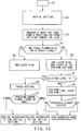
- FIG. 7 is a flow chart of a disk judgment program accommodated in the system controlling portion 100.
- a disk distinguishing function starts, first initial setting is done automatically. An optical system, a signal processing portion and a servo system are set for CD. Then A lens is set at a certain position for picking up a focus error signal to judge the S-letter level (steps A1 to A4). If the S-letter level is high (H), the disk is judged to be CD or one-layer DVD. Then after adjusting the focus, the disk is rotated and judgment is made on a tracking error signal (steps A5 to A7). As the tracking error signal, an (E-F) signal is used. With the tracking error signal larger than a certain value, the disk is judged to be CD and with the tracking error signal smaller than the certain value, the disk is judged to be DVD. The certain value can be set by preliminary experiments for the level of distinguishing CDs and DVDs.
- step A4 if the S-letter level is low (L), the disk is judged to be DVD-ROM or DVD-RAM of two layers. Then after adjusting the focus, the disk is rotated (steps A10, A11). And judgment is made on the existence of a discrimination signal. If the discrimination signal (as shown in FIG. 6) exists, the disk is judged to be DVD-RAM and if it does not exist, the disk is judged to be DVD-ROM (step A12).
- the disk is rotated while controlling the tracking with the CLV (Constant Linear Velocity) control off and a forcible constant rotation control is achieved.
- CLV Constant Linear Velocity
- a rotation servo or tracking servo system of the disk may be rampant with the CLV control on when the setting of the device does not meet the kind of the disk.
- a DVD-ROM has a pit depth of ⁇ /4
- a DVD-RAM has a pit depth of ⁇ /8. Therefore, without clear acknowledgment of the kind of the disk, a correct tracking control cannot be conducted. Besides, as mentioned above, there is a possibility that a rotation servo system or a tracking servo system of the disk may be rampant.
- FIG. 8 is another flow chart of a disk judgment program accommodated in the system controlling portion 100.
- This program differs from the program shown in FIG. 7 only in the initial setting conditions. That is, in this program, as the initial setting following the step A1, a lens for DVD is set for the optical system, and a servo system and a signal processing system are set for DVD.
- the output from the phase difference detector 31 is used for a tracking error signal in the step A7.
- the disk is rotated for checking the size of the tracking signal, and if the signal is large, the disk is judged to be DVD, and if the signal is small, the disk is judged to be CD. Since the other steps are the same as the processing shown in FIG. 7, details are not described here.
- FIG. 9 is still another flow chart of a disk judgment program accommodated in the system controlling portion 100.
- a discrimination signal is searched for judging either of them.
- judgment is made on whether two focal planes exist for a focus signal by gradually moving a lens from a position far from a disk toward the disk (steps C1, C2). If two focal planes exist for a focus signal, it is a two-layer disk (DVD-ROM), and if one focal plane exists, it is a one-layer disk (DVD-RAM).
- FIG. 10 is still another flow chart of a disk judgment program accommodated in the system controlling portion 100.
- this judgment program after the initial setting, judgment is made whether two focal planes exist for a focus signal, that is, whether a detection signal for an S-letter curve can be obtained twice by gradually moving a lens positioned far from a disk toward the disk (steps D1 to D4). If two focal planes exist for a focus signal, it is judged to be a two-layer disk (two-layer DVD-ROM) (step D5). If one focal plane exist, it is a one-layer disk, namely, either of CD, DVD-RAM, or one-layer DVD-ROM.
- the S-letter level of a focus error signal If the S-letter level is high (H), it is CD or one-layer DVD-ROM (steps D6, D7). If the S-letter level is high, a judging process the same as the steps A5 to A7 shown in FIGs. 7 and 8 are conducted. If the S-letter level is low (L), it is one-layer DVD-ROM or DVD-RAM (step D8), then judgment is made on whether it is a one-layer DVD-ROM or DVD-RAM in the process the same as steps A11, A12 shown in FIGs. 7 and 8.
- FIG. 11 is another embodiment of the invention.
- numeral 41 denotes an operation input interface for receiving an operation signal from a remote control operator 42 and supplying it to the system controlling portion 100. If a user starts reproduction or processing, the device displays at the display portion a requirement of the input of a disk distinguishing signal.
- the display portion may be a television screen or a display portion of the remote control operator 42, and further, a warning sound may be added. If a disk distinguishing signal is already inputted, the next process will be conducted.
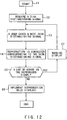
- FIG. 12 is an embodiment of a flow chart of the above-mentioned system.
- a requirement of the input of a disk distinguishing signal is shown in a display portion (sound may be added) (steps E1 to E2).
- the system automatically starts for rotating the disk (but with an usual servo operation curbed) and starting a focus servo and a tracking servo (steps E3, E4).
- the judgment is made on whether a lot of errors exist in a reproduced signal. If there is no error, a blue safety sign is indicated in the display portion and reproduction or recording is implemented (steps E5, E6). However, if a servo signal is unusual or there is an error in a reproduced signal, a warning sign is indicated in the display portion requesting another judgment input (step E7).
- the user inputs a disk judgment input responding to the warning so as to control the device for finding the corresponding kind of the disk.
- a blue safety sign is indicated in the display portion, the user stops the judgment input.
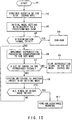
- FIG. 13 is another embodiment of a flow chart of the above-mentioned system.
- a device itself automatically designates a disk distinguishing signal cyclically for implementing reproduction corresponding to the disk distinguishing signal. That is, judgment is made on whether a lot of errors exist in a reproduced signal or not, and if there is no error, the placed disk is judged to be corresponding to the disk distinguishing signal, and the reproduction processing is started (steps F1 to F5). However, if a lot of errors exist, judgment is made on whether all the settings of conceivable kinds of disks are tried or not, and if not all of them are tried, a process of the step F2 will be conducted again for trying the next setting again. If judgment is made that all the settings of the conceivable kinds of disks have been tried in the step F6, judgment is made that a foreign substance is placed and warning sign is indicated (steps F6, F7).
- FIG. 14 is still another embodiment of a flow chart of the above-mentioned system.
- This flow chart shown a method of searching a threshold signal denoting a DVD-RAM as shown in FIG. 6. This is because judgment on whether the disk is recordable or not is regarded important for preventing recording error.
- a disk is rotated slowly and judgment is made on whether a threshold signal exists or not. If there is a threshold signal, it is judged to be DVD-RAM (steps A1, G1 to G3). If there is no threshold signal, judgment should be made on whether it is CD, one-layer DVD-ROM, or two-layer DVD-ROM. Therefore, initial setting of the system is conducted as mentioned above (step G4), and the S-letter level is detected (steps G5, G6). If the S-letter level is lower than a certain value, it is judged to be a two-layer DVD-ROM. If the S-letter level is higher than the certain value, it is judged to be a CD or a one-layer DVD-ROM (step G8).
- the focus is set and the disk is rotated for about a half turn and a tp tracking servo is turned on.
- the rotation servo is turned off and the rotation is made forcibly. This is for preventing rampant rotation of the disk.
- the tracking servo judgment is made on the size of the tracking error signal.
- the tracking servo is set for DVD or for CD according to the initial setting. According to the initial setting conditions and the size of the tracking error signal, judgment can be made on whether it is CD or DVD (steps G9, G10).
- the system controlling means reset the signal processing portion, the focus servo means and the tracking servo means so as to correspond to the judged kind of the disk for enabling the system to conduct reproduction or recording.
- a function to make judgment on whether the judged kind of disk is the disk requested by the user may be added. Namely, in the case a user placed a CD inadvertently instead of a DVD, the reproduction device would automatically switches to the CD reproduction mode to start reproduction operation. Then the display does not show a picture despite the user's anticipation since the user assumes a DVD is placed. In such a case the user may misunderstand that it is because of the malfunction of the reproduction device. In order to prevent such a misunderstanding, it is also possible to allow a user to input information on the kind of the disk to be reproduced by an operation device so as to compare the result of the automatic judgment and the inputted information, and in the case there is discrepancy, it is indicated in the display portion.
- the function shown in FIG. 13 is to find whether the kind of the disk placed in the reproduction device is different from the kind of the disk to be reproduced by the reproduction device.
- This function may be used in combination with the function explained with reference to FIGS. 7 to 10. Namely, a combination of after the judgment on whether the amount of error is much or not is judged by the function of FIG. 13 and automatic judgment on the kind of the disk, an automatic judgment function of FIGs. 7 to 10 is applied. Accordingly, when a foreign substance is placed, it can be detected in an early stage.
- disk judgment mentioned above utilizes properties of the disks
- the following method may be used in the case of judging whether the placed disk is appropriate or not according to the amount of the detected noise.
- FIG. 15 is still another embodiment of a flow chart of the disk distinguishing process the above-mentioned system.
- step H1 when a disk is placed, the disk is rotated automatically (steps H1, H2) with the servo off.
- a certain focus is set, and a beam characteristic is set corresponding to an assumed disk (step H3).
- a threshold signal is detected, since the disk is a DVD-RAM, the device is prepared for recording, and it is indicated at the front part of the reproduction device (step H5).
- step H6 reproduction processing is conducted (step H6). If a lot of errors are found in the reproduced signal, the kind of the present disk is judged not to be the one set by the reproduction device (step H7). Then another reproduction processing is tried with another kind of a disk mode (step H8).
- the device itself designates a disk distinguishing signal automatically and cyclically to conduct reproduction according to the disk distinguishing signal. Then judgment is made on whether a lot of errors exist in the reproduced signal, and when there is no error, the placed disk is judged to be corresponding to the set disk distinguishing signal, and the reproduction processing follows (step H9). However, when there are a lot of errors, judgment is made on whether all the conceivable settings of the kinds of the disks have been tried (step H10), and if not, the program returns to the step H6. In the step H10, after trying all the conceivable settings of the kinds of the disks, judgment is made that a foreign substance is placed and a warning sign is indicated (step H11).
- an initial mode is automatically set at the time of placing a disk, and also in the step H8, input information of switching the kind of the disk is automatically designated. But it is possible that a user may operate the designation manually or by a remote controller operation.
- FIGS. 1 and 17 An optical system of a light head is illustrated in FIGS. 1 and 17.
- a divergent laser beam having a wavelength of 650 nm is generated from a semiconductor laser 350.
- a reproduction laser beam with a substantially constant intensity is generated from the semiconductor laser 350.
- a recording laser beam having a comparatively large light intensity processed with intensity modulation according to the recorded data is generated.
- an erasing laser beam having a substantially constant intensity larger than the beam for reproduction is generated.
- the laser beam outputted from the semiconductor laser 350 is collimated by a collimator lens 352 and enters a half prism 353 as a collimate laser beam. Then the laser beam goes straight through a half mirror 353A provided in the half prism 353 toward an object lens 334 via a first or second aperture 354 or 359 later described.
- the first and second apertures 354, 359 are selected according to the thickness of the transparent substrate of an optical disk 11 (1.2 mm (see FIG. 1A) or 0.6 mm (see FIGs. 1B and 1C) and the size of the light beam irradiated to the optical disk 11 is selected according to the thickness of the transparent substrate as later described.
- the laser beam collected by the object lens 334 after passing through a first or second aperture 354 or 359 is directed to the optical disk 11, refracted by the transparent substrate of the optical disk 11, and collected to a reflecting layer formed on the transparent substrate so as to form a beam spot on the reflecting layer (recording surface).
- a smallest beam spot corresponding to the beam waist of the laser beam is formed on the reflecting layer while the object lens 334 is maintained in the focusing state.
- a track is formed concentrically or spirally as the information recording area, and a physical recording portion such as a pit is formed in the track.
- a track servo mechanism functions to finely move the object lens 334 or the light head for maintaining the tracking conditions where the track is traced by a laser beam.
- a laser beam for reproduction is modulated at the recording portion of a track formed on the reflecting layer, and the modulated laser beam is reflected from the reflecting layer.
- physical change is provided to the reflecting layer in the track by the modulated laser beam to form a recording portion. Further, in erasing, the physical change provided to the recording portion is revived by irradiating a laser beam for erasure to the recording portion.
- the laser beam reflected from the reflecting laser is again collected by the object lens 334, and returned to the half prism 353 via the first or second aperture 354 or 359.
- the laser beam reflected by the half mirror 353A in the half prism 353 is directed to a projection lens 357 and collected to a light detector 358 by the projection lens 357.
- the laser beam for reproduction modulated at the recording portion is converted to a detection signal by the detector 358, and a reproduction signal, a focus signal and a tracking signal are generated by a signal processing circuit (not illustrated) from the detection signal.
- a laser beam for recording or erasure is detected by the detector 358, and a focus signal and a tracking signal are generated by the signal processing circuit from the detection signal.
- first and second apertures 354, 359 are selected according to the structure of the optical disk 11, that is, the thickness of the transparent substrate of the optical disk, as illustrated in FIG. 16 or 17, and used for limiting the laser beam directed to the object lens 34.
- the aperture 354 is selected so as to project a collective light beam having a 0.6 aperture, which is larger than that of a light beam passing through the aperture 359.
- the laser beam passed through the aperture is collected by the object lens and irradiated on the reflecting layer via the transparent substrate so as to form a smallest beam spot of 0.9 ⁇ m.
- the light reflected by the reflecting layer is detected by the detector 358.
- the reflected light of the sub beam is neglected as explained with FIGs. 3 and 5.
- Data is read out by a so-called one beam method.
- the aperture 359 is selected so as to project a collective light beam having a 0.36 aperture, which is smaller than that of a light beam passing through the aperture 354. Accordingly, in an optical system shown in FIG. 17, a laser beam to pass through is limited compared with the optical system, which has selected an aperture 354.
- the laser beam having the beam diameter narrowed by passing through the aperture 359 is collected by the object lens 334 and irradiated on the reflecting layer via the transparent substrate having a thickness of 1.2 mm so as to form a smallest beam spot of 1.6 ⁇ m.
- the light reflected by the reflecting layer is detected by the detector 358.
- the reflected light of the sub beam is also adopted. Data is read out by a so-called three beam method.
- the aperture 359 having an aperture smaller than that of the aperture 354 is selected, even when information is reproduced from or recorded on an optical disk having a comparatively thick transparent substrate, a laser beam enters to the transparent substrate in a narrow range from the object lens 334 with a small aberration to the laser beam, and thus a minute beam spot can be formed on the reflecting layer. That is, since a light beam with the size limitation is collected by the object lens 334, the focal depth at the focal point becomes large, in other words, the focus tolerance error becomes large.
- a beam spot on the reflecting layer can be kept as a smallest beam spot comparatively easily without drastically changing the beam spot size or generating halo in the vicinity of the beam spot.
- FIGS. 18A and 18B illustrate other configurations for selecting the apertures 354 and 359.
- FIG. 18A illustrates a configuration of a flat plate 360 with apertures 354, 359 having different numerical apertures aligned along a straight line. By the linear movement of the flat plate 360 as indicated with the arrow, the apertures 354 and 359 are selected.
- FIG. 18B illustrates a configuration of a segment-like plate 362 with apertures 354, 359 having different numerical apertures arranged along the arc. By the rotation of the segment-like plate 362 by a certain angle as indicated with the arrow, the apertures 354 and 359 are selected. Selection of the apertures 354 and 359 can be made not only by this configuration but other configuration can be applied such as limitation of the aperture with a plurality of movable plates as in a lens shutter of a camera.
- the aperture 354 is selected so as to project a collective light beam having a numerical aperture of 0.6
- the aperture 359 is selected so as to provide a collective light beam having a numerical aperture of 0.36.
- the aperture 354 is selected so as to project a collective light beam having a numerical aperture of 0.5 to 0.65
- the aperture 359 is selected so as to provide a collective light beam having a numerical aperture of 0.3 to 0.5.
- optical system not only the above-mentioned configuration but various embodiments can be applied as well.
- various embodiments can be applied. For example, a plurality of lenses with mechanical switching can be adopted. Further, a plurality of pick-up units integrally comprising a lens and a light beam generating source, which can be selected and switched can be adopted as well.
- a pick-up device which has one object lense and a plural laser beam generating sources having different wavelenghs respectively. And the laser beam generating sources are, selectively, used according to a kind of the disk.
- FIG. 19 illustrates the outline of the reproduction device of the present invention.
- the output of a pick-up 403 capable of changing or switching the reading characteristics according to the kind of the optical disk 401 is inputted to the signal (data) processing system 404.
- the signal (data) processing system 404 comprises a demodulation circuit for dealing with 8-14 modulation signals (CD), 8-16 modulation signals (DVD) and the like, demodulating the input signal according to the input, and correcting errors. Furthermore, a separation circuit for separating a data stream and a decoder for decoding separated data.
- Reproduced signals from the pick-up 403 are used by the servo system 405 as mentioned above.
- Tracking or focus control signals from the servo system 405 are returned to the pick-up 403.
- Speed control signals for controlling the rotation of the optical disk 401 are also returned from the servo system 405 to the pick-up motor 402.
- the system controlling portion 406 can switch characteristics or processing contents of the signal (data) processing system 404 according to the switch of the numerical aperture. It also can switch response characteristics of the servo system 405.
- Various embodiments of pick-up 403 can be applied, and thus one suitable for the disk, or one capable of switching characteristics can be selected. Either a type having a plurality of laser beams as the light source or a type having one laser beam can be used. Either a type having one lens system or a type having a plurality of lens systems capable of switching can be used.
- the systems is an optical disk reproduction device for reproducing recorded signals from a plurality of disks having different track pitches via an optical pick-up.
- the device comprises a numerical aperture changing means to change the numerical aperture of a beam outputted from the optical pick-up according to the disk to be reproduced and a signal processing system changing means to change the characteristics of the signal processing system connected to the later stage of the above-mentioned pick-up subsequent to the change of the numerical aperture of the beam by the numerical aperture changing means according to the disk to be reproduced.
- the system may comprise a data processing system switching means for switching the characteristics of the date processing system connected to the later stage of the pick-up subsequent to the change of the numerical aperture of the beam by the numerical aperture changing means according to the recording format of the disk to be reproduced.
- the system may comprise a data processing system switching means for switching the characteristics of the data processing system connected to the later stage of the pick-up following the change of the numerical aperture of the beam by the numerical aperture changing means according to the recording format of the disk to be reproduced.
- the switching means may comprise a software provided in the system controlling portion 406 or a dedicated hardware.
- signal processing functions can be switched according to the switch of optical systems, and thus a pick-up, reproduction and controlling system suitable for the disk can be provided.
- the invention may effectively be applied to a reproduction device for reproducing an optical disk having a plurality of layers.
- a reproduction device for reproducing an optical disk having a plurality of layers.
- it can effectively be applied to the case of not only judging the disk but also of switching the state of the reproduction device.
- some of reproduction devices automatically have a state switching mode when operation input from the outside is applied or the reproduction of one program or one side of a disk is finished.
- the state switching mode for example, a forcible focus adjusting operation is implemented. And a signal recording surface of another layer is searched.
- an S-letter level detection means mentioned above is effectively used.
- the wave-form of the S-letter signal reaches a certain level at the time of just focus. Therefore, by providing a controlling program for forcibly driving the focus adjusting mechanism and switching processing characteristics of the signal processing portion whenever a certain value of a detected signal of an S-letter wave-form from the S-letter signal detection means, the signal processing state corresponding to the recording format of the disk to be reproduced can be prepared easily.
- Various methods can be used for checking whether the signal processing state is appropriate or not. For example, when the error rate in the error correction circuit for processing reproduced signals is low, judgment can be made that an appropriate signal processing state is obtained. Or the state of the signal processing route can be judged by whether an appropriate level is achieved in the signal processing route.
- operation of switching from the MPEG-1 processing state to the MPEG-2 processing state can be presented. That is, in a disk having a plurality of sheets attached to each other, sometimes image compressed data of MPEG-2 are recorded in a first layer and image compressed data of MPEG-1 are recorded in a second layer.
- video information is recorded in one layer and sound information and superimposition information is recorded in the other layer. Accordingly, various kinds of information can be recorded in a combination.
- FIGS. 20A to 20D illustrate examples of combined disks having two pieces of 0.6 mm thickness disks adhered 501, 601.
- a signal of the MPEG-1 standard is recorded in a first layer (or a second layer), and a signal of the MPEG-2 standard is recorded in a second layer (or a first layer).
- a function of switching signal processing circuits when a layer of a signal recording surface is detected is provided.
- the detecting function of the layer surface which is the interface of layers is effectively utilized. The layer surface detecting function will be described later.
- a focus control is forcibly implemented in order to proceed to signal reproduction of the second layer. If a layer surface is detected in the halfway of the focus control, automatic switching of signal processing circuits is implemented.
- a combined disk 601 has a first layer of DVD and a second layer of CD. That is, a first track having a higher recording density is formed in the first layer. A second track having a lower recording density is formed in the second layer. The first and second tracks have different track pitches.
- switching of signal processing circuit is conducted as mentioned above. That is, when a signal of a second layer is reproduced just after the reproduction of a signal of a first layer, a focus control is forcibly implemented. If a second layer is detected in the halfway of the focus control, automatic switching of signal processing circuits is conducted. In this case, a circuit is switched to a signal processing circuit for CD.
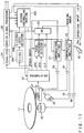
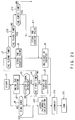
- FIG. 21 shows a configuration of a disk reproduction device of the present invention.
- An optical disk 511 is rotated by a disk motor 12.
- a pick-up device 21 optically reads out the recorded signal of an optical disk 511.
- An output signal of the pick-up device 21 is amplified with a preamplifier 23.
- An output of the preamplifier 23 is supplied to a data processor 520 and a servo processor 530.
- the data processor 520 conducts demodulation processing and an error correction processing.
- Video or audio information processed with the data processor 520 is supplied to an MPEG2 processor 521 and an MPEG1 processor 522.
- the MPEG2 processor 521 and the MPEG1 processor 522 conduct combination processing of the video information and combination processing of the audio information.
- the video information combined with the MPEG2 processor 521 and the MPEG1 processor 522 is inputted to a video processor 524.
- the video processor 524 implements gain control of a video signal, color adjustment to a color signal and image quality adjustment to a luminance signal.
- the signal from the video processor 524 is supplied to an NTSC encoder 526 and converted to a video signal of an NTSC format.
- the audio information combined with the MPEG2 processor 521 and the MPEG1 processor 522 is inputted to a digital audio signal processor 523.
- the audio signal applied with gain adjustment or separation treatment here is supplied to the next digital analog converter (not illustrated).
- the above-mentioned reproduction device can reproduce CD information. Audio information recorded in a CD is separated with a data processor 520 and demodulated with a CD information demodulator in the servo processor 530. The demodulated CD signal is supplied to a digital audio processor 523.
- the servo processor 530 generates various kinds of control signals utilizing a high frequency signal from the preamplifier 23. Examples thereof include a focus control signal and a tracking control signal for the pick-up device 21 and a control signal for the disk motor 12.
- both an optical disk shown in FIGS. 20A and 20B and an optical disk shown in FIGS. 20C and 20D can be reproduced.
- a disk distinguishing function operates when a disk is placed.
- the focus control portion is forcibly driven.
- a plurality of S-letter signals can be obtained from the S-letter level detector 26B (see FIG. 11) included in the inside of the data processing portion 520. That is, whenever the focus of a light beam passes on the layer surface of a disk, an S-letter signal is obtained.
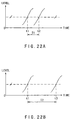
- FIG. 22A shows an S-letter signal, which can be obtained when a disk 501 of FIG. 20A is mounted on a reproduction device and the focus control portion is forcibly operated. If a lens moves from a position distant from a disk toward the disk, the beam spot passes on two signal recording surfaces. In the disk 501, the two signal recording surfaces are adjacent.
- the disk type By measuring the time T1 between the point at which the beam spot passes on a first signal recording surface t1 and the point at which the beam spot passes on a second signal recording surface t2, the disk type can be judged.
- FIG. 22B shows an S-letter signal, which can be obtained when a disk 601 of FIG. 20C is mounted on a reproduction device and the focus control portion is forcibly operated.
- the beam spot passes on two signal recording surfaces.
- the distance between the two signal recording surfaces is larger than the distance between the two signal recording surfaces in the above-mentioned disk 501.
- the disk type can be judged.
- the S-letter signal is detected also when a beam spot passes on the surface (not a signal recording surface) of the disk. However, since the level of the S-letter detection signal is low, it is removed with the noise elimination filter 26A (see FIG. 11).
- FIG. 23 shows an algorithm of a function to judge the disk kind by detecting the thickness of the disk layer. If a disk is placed in a reproduction device, an actuator of the focus adjustment device is forcibly driven. That is, the focus control is forcibly implemented (steps J1, J2). Judgment is made on if an S-letter signal is obtained in the halfway of the focus control (step J3). In the case an S-letter signal is detected, judgment is made on if it is the first detection (J4). If it is the first detection, counting operation of a counter is initiated (step J5). And judgment is made on whether a predetermined time is over or not from the point at which the focus control is initiated (step J6). If the present point is within the predetermined time, the focus control is continued.
- the subject disk is judged to have one signal recording surface.
- step J3 judgment is made on if an S-letter signal is obtained or not.
- the system is designed also for distinguishing disks having more layers. That is, judgment is made on whether an S-letter signal is obtained or not during the focus control (step J3). In the case an S-letter signal is detected, judgment is made on whether it is the third detection (J10). If it is the third detection, a second counted value of the counter is preserved (step J11). Then the counter is started again (step J9), and the system returns to the step J2. At this stage, it can be learned that the disk has three signal recording surfaces.
- step J3 judgment is made on whether an S-letter signal is obtained or not during the focus control. In the case an S-letter signal is detected, judgment is made on whether it is the fourth detection (J10). If it is the fourth detection, a third counted value of the counter is preserved (J11). Then the counter is started again (step J9), and the system returns to the step J2.
- the thickness information can be used as reference data in conducting focus control with a pick-up device. For example, a beam spot is applied to the data recording surface of a second layer after the reproduction of data in a first layer of a two-layer disk, the above-mentioned thickness information can be used at the focus control portion. That is, at the time of focus adjustment, the thickness information can be used as the control information for driving the actuator.
- the above-mentioned thickness information can be used with a fine modification.
- the coil current for driving the actuator differs between the case of distinguishing a disk and the case of reproducing data, the above-mentioned thickness information is used with a fine modification.
- counting may be initiated at the point when the actuator is started to drive, that is, from the step J2.
- a disk of FIG. 1B and a disk of FIG. 1C can be distinguished according to the count number when the first signal recording surface is detected.
- FIG. 24A illustrates a CD reproduction device.
- An optical disk 601 (see FIG. 24B) is rotated and driven by a disk motor 610. Recorded information in the optical disk 601 is read out with a pick-up device 611.
- a high frequency signal outputted from the pick-up device 611 is amplified with a preamplifier 612.
- the output from the preamplifier 612 is inputted to a servo processor 618 as well as to a CD interface 613.
- an 8/14 conversion (EFM) is conducted and a modulated signal is demodulated.
- the demodulated signal is inputted to an MPEG1 processor 614, providing a decoder.
- demodulation of a video signal and demodulation of an audio signal are conducted.
- the demodulated video signal is inputted to an NTSC encoder 615, and the demodulated audio signal is inputted to an audio digital analog converter 616.
- the above-mentioned CD player is designed so as to the focus adjustment range of the pick-up device 611 fits to a conventional CD.
- a disk shown in FIG. 20C has a substrate thickness and a signal recording surface compatible to the CD standard. Therefore, the disk shown in FIG. 20C can be mounted in a conventional CD player so as to reproduce a signal recorded in a second layer. That is, a beam from a pick-up of a CD player is designed so as to fit to a disk having a 1.2 mm thickness. Accordingly, the focus of the beam can easily meet the recording surface of the second layer.
Applications Claiming Priority (3)
| Application Number | Priority Date | Filing Date | Title |
|---|---|---|---|
| JP2561296 | 1996-02-13 | ||
| JP25612/96 | 1996-02-13 | ||
| JP2561296 | 1996-02-13 |
Publications (3)
| Publication Number | Publication Date |
|---|---|
| EP0790604A2 true EP0790604A2 (fr) | 1997-08-20 |
| EP0790604A3 EP0790604A3 (fr) | 1998-02-04 |
| EP0790604B1 EP0790604B1 (fr) | 2004-01-07 |
Family
ID=12170721
Family Applications (1)
| Application Number | Title | Priority Date | Filing Date |
|---|---|---|---|
| EP97102352A Expired - Lifetime EP0790604B1 (fr) | 1996-02-13 | 1997-02-13 | Dispositif de lecture pour disques optiques |
Country Status (6)
| Country | Link |
|---|---|
| US (1) | US5903531A (fr) |
| EP (1) | EP0790604B1 (fr) |
| KR (1) | KR100317966B1 (fr) |
| CN (1) | CN1103993C (fr) |
| DE (1) | DE69727090T2 (fr) |
| TW (1) | TW453493U (fr) |
Cited By (10)
| Publication number | Priority date | Publication date | Assignee | Title |
|---|---|---|---|---|
| EP0810588A2 (fr) * | 1996-05-28 | 1997-12-03 | Pioneer Electronic Corporation | Appareil pour distinguer des disques pour un appareil de lecture de disques optiques |
| EP0862164A2 (fr) * | 1997-02-26 | 1998-09-02 | Sony Corporation | Unité de disques optiques |
| EP0899732A1 (fr) * | 1997-08-26 | 1999-03-03 | SANYO ELECTRIC Co., Ltd. | Méthode pour discriminer des disques avec des réflexions similaires |
| EP1195759A2 (fr) * | 2000-10-05 | 2002-04-10 | Mitsubishi Denki Kabushiki Kaisha | Appareil de reproduction des disques optiques et méthode de discrimination de type de disque |
| WO2002061488A1 (fr) * | 2001-01-30 | 2002-08-08 | Matsushita Electric Industrial Co., Ltd. | Miroir variable et dispositif d'information comprenant ce miroir variable |
| EP1313101A2 (fr) * | 2001-11-16 | 2003-05-21 | Victor Company Of Japan, Ltd. | Procédé de discrimination de type de disque optique et appareil de disque optique utilisant un tel procédé |
| WO2003079345A1 (fr) * | 2002-03-20 | 2003-09-25 | Lg Electronics Inc. | Procede de servocommande d'un appareil a disque optique |
| EP1473719A2 (fr) * | 2003-04-21 | 2004-11-03 | Pioneer Corporation | Appareil de reproduction, méthode de reproduction et support d'enregistrement avec programme de commande de reproduction en forme lisible par ordinateur enregistré dessus |
| US7068415B2 (en) | 2002-01-29 | 2006-06-27 | Matsushita Electric Industrial Co., Ltd. | Deformable mirror and optical controller including the deformable mirror |
| US7368846B2 (en) | 2002-11-06 | 2008-05-06 | Matsushita Electric Industrial Co., Ltd. | Microactuator with displacement sensing function and deformable mirror including the microactuator |
Families Citing this family (48)
| Publication number | Priority date | Publication date | Assignee | Title |
|---|---|---|---|---|
| EP0833311B1 (fr) | 1996-09-25 | 2001-12-12 | Victor Company Of Japan, Ltd. | Dispositif pour déterminer le genre de disque, dispositif de reproduction de disque optique, et dispositif de détection de signal d'erreur de suivi de piste |
| JPH10334574A (ja) * | 1997-05-27 | 1998-12-18 | Victor Co Of Japan Ltd | 光ディスク判別装置 |
| JPH10334570A (ja) * | 1997-05-27 | 1998-12-18 | Toshiba Corp | 光ディスク判別装置 |
| US6826139B1 (en) * | 1997-08-30 | 2004-11-30 | Samsung Electronics Co., Ltd. | Hybrid disc and method and apparatus for discriminating same |
| US6728076B1 (en) | 1997-12-06 | 2004-04-27 | Samsung Electronics Co., Ltd | Cartridge having sensor hole to be opened/closed and apparatus and method for driving the same |
| WO1999040583A1 (fr) * | 1998-02-03 | 1999-08-12 | Matsushita Electric Industrial Co., Ltd. | Procede servant a identifier un type de disque |
| US6205112B1 (en) * | 1998-02-17 | 2001-03-20 | Gateway, Inc. | Multipurpose optical disc having different formats on opposing sides |
| KR20000047312A (ko) * | 1998-12-31 | 2000-07-25 | 구자홍 | 광 디스크의 재생배속 가변 조정장치 및 조정방법 |
| GB9906762D0 (en) * | 1999-03-25 | 1999-05-19 | Philips Electronics Nv | Optical disc player |
| KR100606665B1 (ko) * | 1999-04-19 | 2006-07-31 | 엘지전자 주식회사 | 광 기록매체의 종류 판별 방법 및 장치 |
| US7012858B1 (en) * | 1999-12-10 | 2006-03-14 | Lg Electronics Inc. | Method for checking the existence of an optical disk using a focusing signal |
| JP3696044B2 (ja) * | 2000-04-21 | 2005-09-14 | 松下電器産業株式会社 | 光ディスク装置とその光ディスク判別方法 |
| US7151729B1 (en) * | 2000-06-29 | 2006-12-19 | Samsung Electronics Co., Ltd. | Optical recording medium having read-only storage area and writeable storage area and recording/reproducing apparatus and method therefor |
| US6928035B2 (en) * | 2000-07-07 | 2005-08-09 | Matsushita Electric Industrial Co., Ltd. | Optical pick-up, optical disk apparatus and information processing apparatus |
| US20080123491A1 (en) * | 2000-09-07 | 2008-05-29 | Samsung Electronics Co., Ltd | Optical recording medium having read-only storage area and writeable storage area and recording/reproducing apparatus and method therefor |
| JP4067781B2 (ja) * | 2001-04-13 | 2008-03-26 | 株式会社日立エルジーデータストレージ | ディスク再生装置 |
| JP4031623B2 (ja) * | 2001-06-15 | 2008-01-09 | 株式会社リコー | 光ディスク記録方法、情報処理方法、光ディスク装置及び情報処理装置 |
| JP2003022536A (ja) * | 2001-07-03 | 2003-01-24 | Tdk Corp | 光ディスクの再生方法及び光ディスク再生装置 |
| JP4770080B2 (ja) * | 2001-07-17 | 2011-09-07 | ソニー株式会社 | 光ピックアップの調整用光ディスク |
| US7161887B2 (en) * | 2001-11-13 | 2007-01-09 | Digeo, Inc. | Method and apparatus for extracting digital data from a medium |
| TWI298156B (en) | 2002-10-24 | 2008-06-21 | Tian Holdings Llc | Discrimination method for light storage device |
| EP1463053A3 (fr) * | 2003-03-25 | 2006-12-06 | Matsushita Electric Industrial Co., Ltd. | Méthode et appareil pour la reconnaissance des disques optiques, tourne-disque optique et méthode et appareil pour faire la distinction entre des couches d'emmagasinage de données |
| JP2004319051A (ja) * | 2003-04-21 | 2004-11-11 | Pioneer Electronic Corp | 情報再生装置及び方法等 |
| JP4042624B2 (ja) * | 2003-05-16 | 2008-02-06 | 株式会社日立製作所 | ディスク装置調整方法、ディスク装置 |
| KR20040107044A (ko) * | 2003-06-12 | 2004-12-20 | 삼성전자주식회사 | 광 디스크 판별 방법 및 그 장치 |
| CN100412972C (zh) * | 2003-09-15 | 2008-08-20 | 宇田控股有限公司 | 光盘片格式的辨识方法 |
| JP4060771B2 (ja) * | 2003-09-16 | 2008-03-12 | 株式会社東芝 | 光ディスク装置及びその制御方法 |
| US20050226114A1 (en) | 2004-03-31 | 2005-10-13 | Stanley Liow | Method and apparatus for generating absolute time in pregroove data |
| JP4342930B2 (ja) * | 2003-12-25 | 2009-10-14 | 株式会社東芝 | 光ディスク装置及びその制御方法及び記録媒体 |
| US7570561B2 (en) * | 2004-05-25 | 2009-08-04 | Bryan Tai | Method for determining type of digital versatile discs |
| US7746745B2 (en) * | 2004-05-25 | 2010-06-29 | Ricky Chang | Method for determining the type of digital versatile disc |
| US7626907B2 (en) * | 2004-05-25 | 2009-12-01 | Ricky Chang | Method and apparatus for determining type of digital versatile disc |
| KR100532612B1 (ko) * | 2004-06-18 | 2005-12-01 | 삼성전자주식회사 | 광디스크 판별 오류시 재생모드 변경방법 및 장치 |
| US20060023573A1 (en) * | 2004-07-29 | 2006-02-02 | Rivera Manuel Jr | Method and system for enhanced optical medium reads |
| US8213290B2 (en) * | 2005-02-16 | 2012-07-03 | Mitsubishi Electric Corporation | Optical disc and optical disc device |
| JP3812584B1 (ja) * | 2005-02-16 | 2006-08-23 | 三菱電機株式会社 | 光ディスク及び光ディスク装置 |
| US8755258B2 (en) | 2005-02-16 | 2014-06-17 | Mitsubishi Electric Corporation | Optical disc and optical disc device |
| US8248907B2 (en) | 2005-02-16 | 2012-08-21 | Mitsubishi Electric Corporation | Optical disc and optical disc device |
| US7564771B2 (en) * | 2005-07-14 | 2009-07-21 | Cinram International Inc. | Bonded pre-recorded and pre-grooved optical disc |
| US20070047410A1 (en) * | 2005-08-28 | 2007-03-01 | Chih-Yuan Chen | Methods for reducing startup time of optical disc drive and apparatuses thereof |
| KR101156709B1 (ko) * | 2005-09-07 | 2012-06-14 | 삼성전자주식회사 | 광디스크장치의 기록파워 제어방법 |
| JP2007080402A (ja) * | 2005-09-15 | 2007-03-29 | Hitachi Ltd | 光ディスク装置 |
| US7609599B2 (en) * | 2006-02-17 | 2009-10-27 | Mediatek Inc. | Method of identifying a type of an optical disc and the device therefor |
| KR100732548B1 (ko) | 2006-02-18 | 2007-06-27 | 삼성전자주식회사 | 스위칭레벨변환기능을 갖는 광 디스크 재생장치 |
| US8588044B2 (en) * | 2008-08-20 | 2013-11-19 | Csr Technology Inc. | CD/DVD mode selection control using laser diode voltage |
| JP5238436B2 (ja) | 2008-09-30 | 2013-07-17 | 株式会社日立製作所 | 光ディスク記録装置、光ディスク再生装置、情報記録方法および情報再生方法 |
| JP5241569B2 (ja) * | 2009-03-05 | 2013-07-17 | 株式会社日立製作所 | 光ディスク記録装置、光ディスク再生装置、情報記録方法および情報再生方法 |
| TW201209809A (en) * | 2010-08-19 | 2012-03-01 | Quanta Storage Inc | A discrimination method of optical disk |
Family Cites Families (22)
| Publication number | Priority date | Publication date | Assignee | Title |
|---|---|---|---|---|
| DE3732875A1 (de) * | 1987-09-30 | 1989-04-20 | Thomson Brandt Gmbh | Optischer aufzeichnungstraeger |
| US5235581A (en) * | 1990-08-09 | 1993-08-10 | Matsushita Electric Industrial Co., Ltd. | Optical recording/reproducing apparatus for optical disks with various disk substrate thicknesses |
| JPH04364229A (ja) * | 1990-11-01 | 1992-12-16 | Matsushita Electric Ind Co Ltd | 光方式記録再生方法および記録媒体、光方式記録再生装置 |
| JP2883215B2 (ja) * | 1991-01-16 | 1999-04-19 | パイオニア株式会社 | 光学式記録媒体演奏装置 |
| US5255262A (en) * | 1991-06-04 | 1993-10-19 | International Business Machines Corporation | Multiple data surface optical data storage system with transmissive data surfaces |
| JPH056571A (ja) * | 1991-06-28 | 1993-01-14 | Pioneer Electron Corp | 光学式情報記録媒体 |
| DE4330794C2 (de) * | 1992-09-10 | 1999-12-23 | Toshiba Kawasaki Kk | Optische Kopfvorrichtung zur Verwendung in einer optischen Aufzeichnungs- und Schreib/Lesevorrichtung |
| JP2532818B2 (ja) * | 1993-02-01 | 1996-09-11 | 松下電器産業株式会社 | 対物レンズおよび光ヘッド装置 |
| WO1995020679A1 (fr) * | 1994-01-26 | 1995-08-03 | Hybridon, Inc. | Procede de detection de taux inferieurs a 10-9 d'oligonucleotides dans des fluides biologiques |
| US5721723A (en) * | 1994-11-18 | 1998-02-24 | Kabushiki Kaisha Toshiba | Objective lens driving device, data recording device, and data reproducing device, all having driver force selectively 120 tutine and positioning the objective lenses |
| DE69528636T2 (de) * | 1994-12-19 | 2003-06-26 | Koninkl Philips Electronics Nv | Mehrschichtiger aufzeichnungsträger und vorrichtung zur abtastung dieses trägers |
| US5726969A (en) * | 1994-12-28 | 1998-03-10 | Matsushita Electric Industrial Co., Ltd. | Optical recording medium having dual information surfaces |
| EP0727776B1 (fr) * | 1995-02-20 | 2003-01-15 | Mitsubishi Denki Kabushiki Kaisha | Dispositif d'entraínement de la lentille d'objectif et dispositif d'enregistrement/lecture d'information optique |
| US6026065A (en) * | 1995-03-04 | 2000-02-15 | Lg Electronics Inc. | Optical pick-up apparatus capable of reading data irrespective of disc type |
| KR0176854B1 (ko) * | 1995-03-04 | 1999-04-15 | 구자홍 | 두께가 상이한 디스크의 호환 기록/재생장치 및 광픽업장치 |
| KR960038847A (ko) * | 1995-04-10 | 1996-11-21 | 김광호 | 다층 구조를 가진 디스크의 검출방법 |
| JPH08293153A (ja) * | 1995-04-24 | 1996-11-05 | Matsushita Electric Ind Co Ltd | ディスク再生装置 |
| JP2995003B2 (ja) * | 1995-05-08 | 1999-12-27 | 三洋電機株式会社 | 光学式再生装置 |
| JP3210549B2 (ja) * | 1995-05-17 | 2001-09-17 | 日本コロムビア株式会社 | 光情報記録媒体 |
| JP3674092B2 (ja) * | 1995-08-09 | 2005-07-20 | ソニー株式会社 | 再生装置 |
| US5787061A (en) * | 1995-08-31 | 1998-07-28 | Sanyo Electric Co., Ltd. | Optical disc recording reproducing apparatus recording/reproducing information to/from optical discs according to different standards |
| HU224503B1 (hu) * | 1995-09-08 | 2005-10-28 | Koninklijke Philips Electronics N.V. | Többrétegű optikai információhordozó |
-
1997
- 1997-02-05 TW TW089217802U patent/TW453493U/zh not_active IP Right Cessation
- 1997-02-12 KR KR1019970004039A patent/KR100317966B1/ko not_active IP Right Cessation
- 1997-02-13 DE DE69727090T patent/DE69727090T2/de not_active Expired - Fee Related
- 1997-02-13 CN CN97102192A patent/CN1103993C/zh not_active Expired - Fee Related
- 1997-02-13 US US08/800,000 patent/US5903531A/en not_active Expired - Fee Related
- 1997-02-13 EP EP97102352A patent/EP0790604B1/fr not_active Expired - Lifetime
Non-Patent Citations (1)
| Title |
|---|
| None |
Cited By (23)
| Publication number | Priority date | Publication date | Assignee | Title |
|---|---|---|---|---|
| EP0810588A3 (fr) * | 1996-05-28 | 1998-03-25 | Pioneer Electronic Corporation | Appareil pour distinguer des disques pour un appareil de lecture de disques optiques |
| US5909419A (en) * | 1996-05-28 | 1999-06-01 | Pioneer Electronic Corporation | Disk discrimination apparatus for an optical disk reproducing apparatus |
| EP0810588A2 (fr) * | 1996-05-28 | 1997-12-03 | Pioneer Electronic Corporation | Appareil pour distinguer des disques pour un appareil de lecture de disques optiques |
| US6424605B1 (en) | 1997-02-26 | 2002-07-23 | Sony Corporation | Optical disc drive |
| EP0862164A2 (fr) * | 1997-02-26 | 1998-09-02 | Sony Corporation | Unité de disques optiques |
| EP0862164A3 (fr) * | 1997-02-26 | 1998-12-09 | Sony Corporation | Unité de disques optiques |
| EP0899732A1 (fr) * | 1997-08-26 | 1999-03-03 | SANYO ELECTRIC Co., Ltd. | Méthode pour discriminer des disques avec des réflexions similaires |
| US6243341B1 (en) | 1997-08-26 | 2001-06-05 | Sanyo Electric Co., Ltd. | Method of distinguishing disks having nearly the same reflectance |
| EP1195759A3 (fr) * | 2000-10-05 | 2003-04-23 | Mitsubishi Denki Kabushiki Kaisha | Appareil de reproduction des disques optiques et méthode de discrimination de type de disque |
| EP1195759A2 (fr) * | 2000-10-05 | 2002-04-10 | Mitsubishi Denki Kabushiki Kaisha | Appareil de reproduction des disques optiques et méthode de discrimination de type de disque |
| US6868052B2 (en) | 2000-10-05 | 2005-03-15 | Mitsubishi Denki Kabushiki Kaisha | Optical disc playback apparatus and method of judging disc type |
| US6952304B2 (en) | 2001-01-30 | 2005-10-04 | Matsushita Electric Industrial Co., Ltd. | Variable mirror and information apparatus comprising variable mirror |
| WO2002061488A1 (fr) * | 2001-01-30 | 2002-08-08 | Matsushita Electric Industrial Co., Ltd. | Miroir variable et dispositif d'information comprenant ce miroir variable |
| US6995897B2 (en) | 2001-01-30 | 2006-02-07 | Matsushita Electric Industrial Co., Ltd. | Deformable mirror and information device having the deformable mirror |
| EP1313101A2 (fr) * | 2001-11-16 | 2003-05-21 | Victor Company Of Japan, Ltd. | Procédé de discrimination de type de disque optique et appareil de disque optique utilisant un tel procédé |
| EP1313101A3 (fr) * | 2001-11-16 | 2004-05-19 | Victor Company Of Japan, Ltd. | Procédé de discrimination de type de disque optique et appareil de disque optique utilisant un tel procédé |
| US7068415B2 (en) | 2002-01-29 | 2006-06-27 | Matsushita Electric Industrial Co., Ltd. | Deformable mirror and optical controller including the deformable mirror |
| WO2003079345A1 (fr) * | 2002-03-20 | 2003-09-25 | Lg Electronics Inc. | Procede de servocommande d'un appareil a disque optique |
| US7656766B2 (en) | 2002-03-20 | 2010-02-02 | Lg Electronics Inc. | Servo-controlling method of an optical disk apparatus |
| US7368846B2 (en) | 2002-11-06 | 2008-05-06 | Matsushita Electric Industrial Co., Ltd. | Microactuator with displacement sensing function and deformable mirror including the microactuator |
| US7635939B2 (en) | 2002-11-06 | 2009-12-22 | Panasonic Corporation | Microactuator with displacement sensing function and deformable mirror including the microactuator |
| EP1473719A2 (fr) * | 2003-04-21 | 2004-11-03 | Pioneer Corporation | Appareil de reproduction, méthode de reproduction et support d'enregistrement avec programme de commande de reproduction en forme lisible par ordinateur enregistré dessus |
| EP1473719A3 (fr) * | 2003-04-21 | 2006-10-04 | Pioneer Corporation | Appareil de reproduction, méthode de reproduction et support d'enregistrement avec programme de commande de reproduction en forme lisible par ordinateur enregistré dessus |
Also Published As
| Publication number | Publication date |
|---|---|
| CN1161535A (zh) | 1997-10-08 |
| DE69727090T2 (de) | 2004-10-14 |
| DE69727090D1 (de) | 2004-02-12 |
| CN1103993C (zh) | 2003-03-26 |
| EP0790604A3 (fr) | 1998-02-04 |
| KR100317966B1 (ko) | 2002-02-19 |
| US5903531A (en) | 1999-05-11 |
| TW453493U (en) | 2001-09-01 |
| EP0790604B1 (fr) | 2004-01-07 |
| KR970063090A (ko) | 1997-09-12 |
Similar Documents
| Publication | Publication Date | Title |
|---|---|---|
| EP0790604B1 (fr) | Dispositif de lecture pour disques optiques | |
| JPH01102749A (ja) | 光学式ディスク再生装置 | |
| US5859824A (en) | Digital disk player | |
| EP0899732B1 (fr) | Méthode pour discriminer des disques avec des réflexions similaires | |
| JP2821453B2 (ja) | ディスク判別装置及び方法 | |
| US5172354A (en) | Compatible disk player for playing multi-size disks and having a mode for selecting one disk type | |
| US6381203B1 (en) | Optical disk reproducing method and apparatus | |
| MY125769A (en) | Optical disc recording and reproducing apparatus | |
| US6590844B2 (en) | Disc-shaped recording medium, disc recording and/or reproducing method and apparatus and tilt detection method | |
| US6134196A (en) | Carriage controller for multi-layer disc | |
| US20030002423A1 (en) | Information medium with multi-layered structure, and apparatus and method using this medium | |
| US6788633B2 (en) | Optical disk reproducing apparatus and setup method | |
| JPH09282785A (ja) | 光学式ディスクの再生装置 | |
| JP3456040B2 (ja) | フォーカス制御装置 | |
| US6791909B2 (en) | Optical disc reproducing apparatus | |
| JP2795127B2 (ja) | 光ディスク装置 | |
| JPH08212583A (ja) | 光ピックアップ装置及び光記録媒体判別装置 | |
| KR100194049B1 (ko) | 디스크 판별 장치 및 방법 | |
| JP2018007138A (ja) | 光ディスク装置 | |
| RU2119686C1 (ru) | Устройство и способ воспроизведения оптических дисков (варианты) | |
| KR100194048B1 (ko) | 디스크 판별 장치 및 방법 | |
| JP3462483B2 (ja) | フォーカスサーボ方法およびこの方法を用いる光ディスク装置 | |
| JPH08339550A (ja) | 光ディスクドライブ装置用制御回路の調整方法 | |
| KR20060057068A (ko) | 광디스크 기기에서의 트래킹 서보 제어장치 및 방법 | |
| JPH1173710A (ja) | ディスク装置 |
Legal Events
| Date | Code | Title | Description |
|---|---|---|---|
| PUAI | Public reference made under article 153(3) epc to a published international application that has entered the european phase |
Free format text: ORIGINAL CODE: 0009012 |
|
| 17P | Request for examination filed |
Effective date: 19970310 |
|
| AK | Designated contracting states |
Kind code of ref document: A2 Designated state(s): DE FR GB NL |
|
| PUAL | Search report despatched |
Free format text: ORIGINAL CODE: 0009013 |
|
| AK | Designated contracting states |
Kind code of ref document: A3 Designated state(s): DE FR GB NL |
|
| 17Q | First examination report despatched |
Effective date: 20020121 |
|
| GRAH | Despatch of communication of intention to grant a patent |
Free format text: ORIGINAL CODE: EPIDOS IGRA |
|
| GRAS | Grant fee paid |
Free format text: ORIGINAL CODE: EPIDOSNIGR3 |
|
| GRAA | (expected) grant |
Free format text: ORIGINAL CODE: 0009210 |
|
| AK | Designated contracting states |
Kind code of ref document: B1 Designated state(s): DE FR GB NL |
|
| PG25 | Lapsed in a contracting state [announced via postgrant information from national office to epo] |
Ref country code: NL Free format text: LAPSE BECAUSE OF FAILURE TO SUBMIT A TRANSLATION OF THE DESCRIPTION OR TO PAY THE FEE WITHIN THE PRESCRIBED TIME-LIMIT Effective date: 20040107 |
|
| REG | Reference to a national code |
Ref country code: GB Ref legal event code: FG4D |
|
| REF | Corresponds to: |
Ref document number: 69727090 Country of ref document: DE Date of ref document: 20040212 Kind code of ref document: P |
|
| NLV1 | Nl: lapsed or annulled due to failure to fulfill the requirements of art. 29p and 29m of the patents act | ||
| ET | Fr: translation filed | ||
| PLBE | No opposition filed within time limit |
Free format text: ORIGINAL CODE: 0009261 |
|
| STAA | Information on the status of an ep patent application or granted ep patent |
Free format text: STATUS: NO OPPOSITION FILED WITHIN TIME LIMIT |
|
| 26N | No opposition filed |
Effective date: 20041008 |
|
| PGFP | Annual fee paid to national office [announced via postgrant information from national office to epo] |
Ref country code: DE Payment date: 20090206 Year of fee payment: 13 |
|
| PGFP | Annual fee paid to national office [announced via postgrant information from national office to epo] |
Ref country code: GB Payment date: 20090211 Year of fee payment: 13 |
|
| PGFP | Annual fee paid to national office [announced via postgrant information from national office to epo] |
Ref country code: FR Payment date: 20090213 Year of fee payment: 13 |
|
| GBPC | Gb: european patent ceased through non-payment of renewal fee |
Effective date: 20100213 |
|
| REG | Reference to a national code |
Ref country code: FR Ref legal event code: ST Effective date: 20101029 |
|
| PG25 | Lapsed in a contracting state [announced via postgrant information from national office to epo] |
Ref country code: FR Free format text: LAPSE BECAUSE OF NON-PAYMENT OF DUE FEES Effective date: 20100301 |
|
| PG25 | Lapsed in a contracting state [announced via postgrant information from national office to epo] |
Ref country code: DE Free format text: LAPSE BECAUSE OF NON-PAYMENT OF DUE FEES Effective date: 20100901 |
|
| PG25 | Lapsed in a contracting state [announced via postgrant information from national office to epo] |
Ref country code: GB Free format text: LAPSE BECAUSE OF NON-PAYMENT OF DUE FEES Effective date: 20100213 |