EP0788767A1 - Appareil diagnostique à rayons X - Google Patents
Appareil diagnostique à rayons X Download PDFInfo
- Publication number
- EP0788767A1 EP0788767A1 EP97200210A EP97200210A EP0788767A1 EP 0788767 A1 EP0788767 A1 EP 0788767A1 EP 97200210 A EP97200210 A EP 97200210A EP 97200210 A EP97200210 A EP 97200210A EP 0788767 A1 EP0788767 A1 EP 0788767A1
- Authority
- EP
- European Patent Office
- Prior art keywords
- table frame
- base unit
- ray diagnostic
- diagnostic device
- attached
- Prior art date
- Legal status (The legal status is an assumption and is not a legal conclusion. Google has not performed a legal analysis and makes no representation as to the accuracy of the status listed.)
- Granted
Links
Images


Classifications
-
- A—HUMAN NECESSITIES
- A61—MEDICAL OR VETERINARY SCIENCE; HYGIENE
- A61B—DIAGNOSIS; SURGERY; IDENTIFICATION
- A61B6/00—Apparatus for radiation diagnosis, e.g. combined with radiation therapy equipment
- A61B6/04—Positioning of patients; Tiltable beds or the like
- A61B6/0487—Motor-assisted positioning
Definitions
- the invention relates to an X-ray diagnostic device with a table frame and with a base unit for mounting the table frame, which can be pivoted about a horizontal axis, and with a displacement device for displacing the table frame relative to the base unit.
- Such an X-ray diagnostic device is known from HU-PS 207 431.
- the displacement of the table frame in relation to the base unit is effected there by a spindle drive.
- a spindle rotatable about its longitudinal axis is attached to the table frame.
- This spindle is driven by a chain from a motor attached to the table frame.
- a threaded nut sits on the spindle, which is attached to the base unit connected to the floor together with a sliding block.
- the sliding block slides in a guide rail attached to the table frame parallel to the spindle.
- the invention is therefore based on the object of designing an X-ray diagnostic device of the type mentioned in such a way that the desired pivoting movement is possible with simple, wear-free and inexpensive components.
- This object is achieved in that a first point of a guide rod is attached to an articulation point on the base unit and that a second point of the guide rod is attached to an articulation point on the table frame so that when the table frame is displaced relative to the base unit, a pivoting movement of the table frame is forced becomes.
- the pivoting movement of the table frame is brought about by much simpler components.
- the guide rod is a simple, preferably straight rod, which must absorb tensile and compressive forces.
- the guide rod is articulated on the base unit or on the table frame in such a way that it can make a pivoting movement in a plane on which the horizontal pivot axis of the table frame is perpendicular. Such an articulated attachment is possible, for example, by simple ball bearings.
- a pivoting movement of the table frame by at least 120 ° is possible, i.e. from a position with the table standing vertically (foot low) to a position in which the table is tilted by at least 30 ° in the other direction from the horizontal position ( Head low).
- This enables X-rays of a patient to be taken in different positions.
- the table frame swivels smoothly and smoothly without jerky movements.
- the table frame has a guide rail which slides on a sliding block articulated to the base unit.
- a large part of the weight of the device rests on the sliding device.
- a large part of the weight is absorbed by the sliding block in this embodiment.
- the sliding block is mounted on the base unit in such a way that it can follow the pivoting movement of the table frame, i.e. that it is pivoted about its bearing axis in synchronism with the table frame.
- the table frame has two parallel guide rails and the base unit has two articulated slide blocks, on each of which one of the guide rails slides. This additionally ensures better support of the table frame and prevents the table frame from tipping over a horizontal longitudinal axis of the table frame that runs perpendicular to the horizontal pivot axis.
- the invention is advantageously designed such that two parallel guide rods are provided and that the articulation points on the base unit or on the table frame each lie on a common horizontal axis. This helps to increase the stability of the device during the swiveling movement. The wear is also kept to a minimum due to the distribution of the forces over as many components as possible.
- the displacement device comprises a toothed rack attached to the table frame and a toothed wheel rotatably mounted on the base unit and engaging in the toothed rack.
- the displacement device comprises two parallel toothed racks attached to the table frame and two parallel toothed wheels which are rotatably mounted on the base unit and each engage in a toothed rack and are fastened on a common drive shaft driven by a motor. This means that the pivoting movement is particularly smooth and even.
- the displacement device comprises a spindle attached to the table frame and a threaded nut which is rotatably mounted on the base unit and engages in the spindle.
- the guide rail and the rack are straight and arranged parallel to each other.
- the X-ray diagnostic device shown in FIG. 1 has a table top unit 18 with a table top 1, which is slidably mounted on a table frame 2 by means of a grid unit 20. Below the table top 1 there is an X-ray tube, not shown, which is attached to a support 5. An x-ray target device 6 with an image intensifier 7 is attached to the carrier 5 above the table top 1. Below the table top 1 there is a base unit 3 connected to the floor and a motor 4. A drive shaft 19 is arranged perpendicular to the plane of the drawing, the central axis of which forms the axis 11. This drive shaft 19 is mounted in the base unit 3 and is driven by the motor 4. Two gearwheels 15 are seated on the drive shaft 19. On the underside of the table frame 2, two parallel, straight racks 14 running parallel to the table top 1 are arranged. One of the toothed wheels 15 engages in each of these toothed racks 14.
- Two sliding blocks 10 are also mounted on the drive shaft 19.
- the ends of two parallel guide rods 9 are mounted in the articulation points A on an axis 12 parallel to the axis 11.
- the other end of the two guide rods 9 is mounted on a further axis 13 parallel to the axis 12 on the table frame 2 in the articulation points B, so that the guide rods 9 can be pivoted about the axis 12 in planes parallel to the plane of the drawing.
- the drive shaft 19 is driven by the motor 4 with the two gear wheels 15.
- the toothed wheels 15 engage in the toothed racks 14, and the table frame 2 is thereby displaced with respect to the base unit 3.
- the table frame 2 slides with the Guide rails 8 on the sliding blocks 10.
- the guide rods 9 cause the table frame 2 to be pivoted about a horizontal axis which is parallel to the axis 11 and can be changed in space.
- the pivot point A of a guide rod 9 moves during the pivoting movement of the table frame 2 on a circular arc around the pivot point B of this guide rod in a plane parallel to the plane of the drawing in FIG. 1.
- FIG. 2 shows the X-ray diagnostic device according to FIG. 1 in a front view.
- An X-ray tube 21 can be seen here below the table top 1.
- the base unit 3 has two vertically standing walls 22 and 23, for example made of metal, in which the drive shaft 19 is mounted.
- a gear wheel 15 is located on the drive shaft 19 on both sides of the motor 4.
- a sliding block 10 is arranged on the drive shaft 19 on both sides of the motor 4.
- the sliding blocks 10 are mounted on the drive shaft 19, i.e. they are not firmly connected to the drive shaft 19 and do not follow the drive rotary movement of the drive shaft 19.
- a guide rail 8 is attached to the table frame 2 above the slide blocks 10.
- a rack 14 is fixedly attached to the table frame 2, partly next to and partly below each guide rail 8.
- the axis 12 with the articulation points A of the guide rods 9 runs through the two walls 22 and 23.
- the axis 13 runs, on which the articulation points B of the guide rods 9 are located.
- the design of the sliding block 10 is to be explained in more detail with reference to the detailed illustration in FIG. 3.
- the area around the drive shaft 19 which is arranged on the right of the motor 4 in FIG. 2 is shown.
- the elements described below are advantageously symmetrical to the central axis of the motor 4, also on the left side of the motor 4 arranged, but omitted for the sake of clarity.
- the elements shown, arranged on one side of the motor 4, would already suffice for the function of the displacement device.
- the drive shaft 19 is mounted in the wall 23 of the base unit 3 by means of a bearing 24.
- the toothed rack 14 is firmly connected to a part of the guide rail 8, which in turn is firmly attached to the table frame 2.
- the guide rail 8 slides on the sliding block 10 on the sliding surface 27.
- the rack 14 On the side facing the motor 4, the rack 14 has a recess at the top into which a part of the sliding block 10 engages, so that a sliding surface 28 results between the sliding block 10 and the rack 14.
- the sliding block 10 and the guide rail 8 serve to absorb a large part of the weight of the device and the patient.
- An embodiment of the X-ray diagnostic device without guide rail 8 and sliding block 10 is also possible, but would lead to a great wear on the rack 14 and the gear wheel 15, since these two elements would then have to bear a large part of the weight.
- the sliding block 10 bears most of the weight on the sliding surface 27. Depending on the pivoting position of the table frame 2, a small part of the weight also rests on the sliding surface 28.
- FIG. 4 shows the X-ray diagnostic device according to the invention when the table top 1 is in the vertical position (foot low position).
- the gear 15 has moved the table frame 2 with the rack 14 such that the gear 15 has reached one end of the rack 14.
- the guide rod 9 has forced the pivoting of the table frame 2 and the table top 1 into the vertical position. In the position shown, the guide rod 9 must absorb almost the entire weight. A slight force acts on the sliding block 10 and loads the sliding surface 28 here (see FIG. 3).
- FIG. 5 shows the X-ray diagnostic device according to the invention in a position in which the table 1 is pivoted by 30 ° to the horizontal position in the opposite direction (head-down position).
- the gear wheels 15 are located at the other end of the toothed racks 14 compared to the position shown in FIG. 4.
- the table frame 2 is shifted by means of the toothed wheels 15 and the toothed racks 14.
- the guide rods 9 move in planes parallel to the plane of the drawing.
- the hinge point B of a guide rod 9 initially moves counterclockwise around the axis 12 until the table 1 has reached the horizontal position. Then this articulation point B moves clockwise around the axis 12 until the guide rod 9 has reached the position shown in FIG. 5.
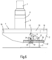
- FIG. 6 shows an alternative embodiment of an X-ray device according to the invention with a spindle drive.
- a sliding block 29 is articulated on the base unit 3, which slides in a guide rail 30 attached to the table frame 2 and can follow the pivoting movement of the table frame 2.
- the sliding block 30 there is a threaded nut 31 which is seated on a spindle 32 which is fixedly attached to the table frame 2 below the guide rail 30 and has a thread which matches the thread of the threaded nut 31.
- the threaded nut 31 is driven, for example, via a chain 33 by a shaft 35 attached to the table frame 2 and driven by a motor 34 with a gear wheel 36.
- the guide rods 9 must be designed so that they can absorb tensile and compressive forces, which are different in different positions of the table frame 2.
- the position of the axes 11, 12 and 13 is selected so that, on the one hand, there is a minimum table height, while at the same time sufficient foot space is guaranteed below the table frame 2 for the operating personnel or the patient.
- the forces on the bearings should be distributed as well as possible in order to keep component wear as low as possible.
- the articulation points A are 435 mm and the articulation points B are 625 mm above the floor.
- the axis 11 runs 255 mm above the ground.
- the distance between the articulation points A and B is about 400 mm and between the articulation points A and the axis 11 about 370 mm.
- the part of the sliding device e.g. the rack in Fig. 1
- the table frame can also make a pivoting movement in addition to the sliding movement.
- the articulation points A must not lie in the plane perpendicular to the floor in which the axis 11 lies.
- the hinge points B are arranged such that their height from the ground is greater than the height of the hinge points A.
- a pair of gearwheels, toothed racks, sliding blocks, guide rails and guide rods are provided.
- a configuration would also be possible in which the elements mentioned are provided only individually or in which only elements that belong together, for example gearwheel and toothed rack, are provided twice.
- the table frame is driven by a toothed wheel or a spindle drive.
- the drive could also be hydraulic, for example. It is only important that the drive causes the table frame to move relative to the base unit.
- the table frame is swiveled uniformly quickly and smoothly in the entire swivel range of at least 120 ° without jerky movements.
- the pivoting of the table frame is also caused by relatively simple and inexpensive to manufacture components.
- the construction and composition of the components is very simple, which is why the device works very reliably and almost maintenance-free.
Applications Claiming Priority (2)
| Application Number | Priority Date | Filing Date | Title |
|---|---|---|---|
| DE19605627 | 1996-02-06 | ||
| DE19605627 | 1996-02-06 |
Publications (2)
| Publication Number | Publication Date |
|---|---|
| EP0788767A1 true EP0788767A1 (fr) | 1997-08-13 |
| EP0788767B1 EP0788767B1 (fr) | 2003-04-16 |
Family
ID=7785502
Family Applications (1)
| Application Number | Title | Priority Date | Filing Date |
|---|---|---|---|
| EP97200210A Expired - Lifetime EP0788767B1 (fr) | 1996-02-06 | 1997-01-27 | Appareil diagnostique à rayons X |
Country Status (4)
| Country | Link |
|---|---|
| US (1) | US5829076A (fr) |
| EP (1) | EP0788767B1 (fr) |
| JP (1) | JP4112037B2 (fr) |
| DE (1) | DE59709812D1 (fr) |
Families Citing this family (7)
| Publication number | Priority date | Publication date | Assignee | Title |
|---|---|---|---|---|
| US6341893B1 (en) * | 1998-07-23 | 2002-01-29 | Canon Kabushiki Kaisha | Photographing stand with a radiation image receiving portion |
| DE19849091A1 (de) * | 1998-10-24 | 2000-05-18 | Philips Corp Intellectual Pty | Röntgenuntersuchungsgerät |
| JP4678999B2 (ja) * | 2001-07-27 | 2011-04-27 | 株式会社東芝 | X線診断装置 |
| DE60118737T2 (de) | 2001-09-19 | 2006-10-19 | The Procter & Gamble Company, Cincinnati | Farbbedruckte Mehrschichtstruktur, ein damit hergestellter absorbierender Artikel und Verfahren zu deren Herstellung |
| DE10253846A1 (de) * | 2002-11-15 | 2004-06-03 | Trumpf Medizin Systeme Gmbh | Operationstisch |
| US7841030B2 (en) * | 2008-05-28 | 2010-11-30 | General Electric Company | Positioning systems and methods |
| KR101496622B1 (ko) * | 2014-08-06 | 2015-02-25 | 신동준 | 엑스레이 테이블 및 이를 구비하는 엑스레이 시스템 |
Citations (4)
| Publication number | Priority date | Publication date | Assignee | Title |
|---|---|---|---|---|
| GB845783A (en) * | 1957-11-25 | 1960-08-24 | Gen Radiological Ltd | A couch for radiography |
| FR1273267A (fr) * | 1960-10-07 | 1961-10-06 | Chirana Praha Np | Table pour l'observation aux rayons chi |
| EP0125713A2 (fr) * | 1983-04-18 | 1984-11-21 | Philips Patentverwaltung GmbH | Appareil de radiographie pivotable autour d'un axe horizontal |
| HU207431B (en) * | 1989-04-19 | 1993-04-28 | Medicor Roentgen Rt | Tilting x-ray examining table |
Family Cites Families (5)
| Publication number | Priority date | Publication date | Assignee | Title |
|---|---|---|---|---|
| US3805080A (en) * | 1971-09-14 | 1974-04-16 | Picker Corp | Safety lowering device for tiltable x-ray table |
| US4618133A (en) * | 1984-12-28 | 1986-10-21 | Fischer Imaging Corporation | Table positioner for radiographic device |
| US5199123A (en) * | 1986-07-18 | 1993-04-06 | General Electric Cgr Sa | Examination bed for NMR or tomodensitometry apparatus |
| JPS63242241A (ja) * | 1987-03-31 | 1988-10-07 | 株式会社東芝 | 移動量検出手段の故障検出装置 |
| US5398356A (en) * | 1993-06-28 | 1995-03-21 | Pfleger; Frederick W. | X-ray table |
-
1997
- 1997-01-27 EP EP97200210A patent/EP0788767B1/fr not_active Expired - Lifetime
- 1997-01-27 DE DE59709812T patent/DE59709812D1/de not_active Expired - Lifetime
- 1997-01-31 US US08/792,319 patent/US5829076A/en not_active Expired - Lifetime
- 1997-02-04 JP JP02159297A patent/JP4112037B2/ja not_active Expired - Fee Related
Patent Citations (4)
| Publication number | Priority date | Publication date | Assignee | Title |
|---|---|---|---|---|
| GB845783A (en) * | 1957-11-25 | 1960-08-24 | Gen Radiological Ltd | A couch for radiography |
| FR1273267A (fr) * | 1960-10-07 | 1961-10-06 | Chirana Praha Np | Table pour l'observation aux rayons chi |
| EP0125713A2 (fr) * | 1983-04-18 | 1984-11-21 | Philips Patentverwaltung GmbH | Appareil de radiographie pivotable autour d'un axe horizontal |
| HU207431B (en) * | 1989-04-19 | 1993-04-28 | Medicor Roentgen Rt | Tilting x-ray examining table |
Also Published As
| Publication number | Publication date |
|---|---|
| US5829076A (en) | 1998-11-03 |
| DE59709812D1 (de) | 2003-05-22 |
| JP4112037B2 (ja) | 2008-07-02 |
| JPH09215690A (ja) | 1997-08-19 |
| EP0788767B1 (fr) | 2003-04-16 |
Similar Documents
| Publication | Publication Date | Title |
|---|---|---|
| DE10196489B3 (de) | Operationstisch, insbesondere für chirurgische Eingriffe | |
| DE3532605A1 (de) | Einrichtung fuer die medizinische diagnostik | |
| DE2251808C3 (de) | Zahnärztlicher Patientenstuhl mit Parallelogrammtragarm | |
| EP0992217A1 (fr) | Système de table d'opération | |
| EP0074019A2 (fr) | Pupitre de contrôle | |
| DE2844647C2 (de) | Längsverstellvorrichtung für einen Fahrzeugsitz, insbesondere einen Kraftfahrzeugsitz | |
| DE3719012A1 (de) | Gestell zum halten einer arbeitsplatte | |
| EP0788767B1 (fr) | Appareil diagnostique à rayons X | |
| EP1131034B1 (fr) | Fauteuil d'examen | |
| DE2439903C2 (de) | Kippvorrichtung für Kraftfahrzeugkarosserien | |
| DE1104713B (de) | Vorrichtung zum Neigen einer Stuetze | |
| DE2557810A1 (de) | Stativ fuer ein roentgenologisches bilderfassungsgeraet | |
| DE3742813C2 (fr) | ||
| DE3212414A1 (de) | Strangfuehrungsgeruest fuer eine stranggiessanlage | |
| DE2525596B2 (de) | Bett, insbesondere Krankenbett, mit neigungs- und höhenverstellbarem Matratzenrahmen | |
| DE3207177C2 (de) | Tisch mit einer in der Höhe und in der Neigung verstellbaren Tischplatte | |
| EP0087498B1 (fr) | Table à plateau réglable | |
| AT410913B (de) | Auflagetisch für eine trennsäge mit einem maschinentisch | |
| DE1285673B (de) | Krankentransportfahrzeug mit einem Gestell zur Aufnahme von Krankentragen | |
| EP0792630A2 (fr) | Lit de traitement | |
| EP3572056B1 (fr) | Dispositif de support de brancard | |
| DE4001256C2 (fr) | ||
| DE3703677C2 (fr) | ||
| EP0661014A2 (fr) | Dispositif pour la variation de la hauteur et/ou de l'inclinaison d'une surface de travail | |
| EP0132448B1 (fr) | Table à plateau réglable |
Legal Events
| Date | Code | Title | Description |
|---|---|---|---|
| PUAI | Public reference made under article 153(3) epc to a published international application that has entered the european phase |
Free format text: ORIGINAL CODE: 0009012 |
|
| AK | Designated contracting states |
Kind code of ref document: A1 Designated state(s): DE FR GB |
|
| 17P | Request for examination filed |
Effective date: 19980213 |
|
| RAP3 | Party data changed (applicant data changed or rights of an application transferred) |
Owner name: KONINKLIJKE PHILIPS ELECTRONICS N.V. Owner name: PHILIPS PATENTVERWALTUNG GMBH |
|
| RAP3 | Party data changed (applicant data changed or rights of an application transferred) |
Owner name: KONINKLIJKE PHILIPS ELECTRONICS N.V. Owner name: PHILIPS CORPORATE INTELLECTUAL PROPERTY GMBH |
|
| GRAG | Despatch of communication of intention to grant |
Free format text: ORIGINAL CODE: EPIDOS AGRA |
|
| 17Q | First examination report despatched |
Effective date: 20020624 |
|
| GRAG | Despatch of communication of intention to grant |
Free format text: ORIGINAL CODE: EPIDOS AGRA |
|
| GRAH | Despatch of communication of intention to grant a patent |
Free format text: ORIGINAL CODE: EPIDOS IGRA |
|
| RAP1 | Party data changed (applicant data changed or rights of an application transferred) |
Owner name: KONINKLIJKE PHILIPS ELECTRONICS N.V. Owner name: PHILIPS CORPORATE INTELLECTUAL PROPERTY GMBH |
|
| GRAH | Despatch of communication of intention to grant a patent |
Free format text: ORIGINAL CODE: EPIDOS IGRA |
|
| GRAA | (expected) grant |
Free format text: ORIGINAL CODE: 0009210 |
|
| AK | Designated contracting states |
Designated state(s): DE FR GB |
|
| PG25 | Lapsed in a contracting state [announced via postgrant information from national office to epo] |
Ref country code: FR Free format text: LAPSE BECAUSE OF FAILURE TO SUBMIT A TRANSLATION OF THE DESCRIPTION OR TO PAY THE FEE WITHIN THE PRESCRIBED TIME-LIMIT Effective date: 20030416 |
|
| REG | Reference to a national code |
Ref country code: GB Ref legal event code: FG4D Free format text: NOT ENGLISH |
|
| RAP2 | Party data changed (patent owner data changed or rights of a patent transferred) |
Owner name: KONINKLIJKE PHILIPS ELECTRONICS N.V. Owner name: PHILIPS INTELLECTUAL PROPERTY & STANDARDS GMBH |
|
| REF | Corresponds to: |
Ref document number: 59709812 Country of ref document: DE Date of ref document: 20030522 Kind code of ref document: P |
|
| GBT | Gb: translation of ep patent filed (gb section 77(6)(a)/1977) | ||
| RAP2 | Party data changed (patent owner data changed or rights of a patent transferred) |
Owner name: KONINKLIJKE PHILIPS ELECTRONICS N.V. Owner name: PHILIPS INTELLECTUAL PROPERTY & STANDARDS GMBH |
|
| REG | Reference to a national code |
Ref country code: GB Ref legal event code: 746 Effective date: 20030804 |
|
| PLBE | No opposition filed within time limit |
Free format text: ORIGINAL CODE: 0009261 |
|
| STAA | Information on the status of an ep patent application or granted ep patent |
Free format text: STATUS: NO OPPOSITION FILED WITHIN TIME LIMIT |
|
| 26N | No opposition filed |
Effective date: 20040119 |
|
| EN | Fr: translation not filed | ||
| PGFP | Annual fee paid to national office [announced via postgrant information from national office to epo] |
Ref country code: GB Payment date: 20100129 Year of fee payment: 14 |
|
| PGFP | Annual fee paid to national office [announced via postgrant information from national office to epo] |
Ref country code: DE Payment date: 20100331 Year of fee payment: 14 |
|
| GBPC | Gb: european patent ceased through non-payment of renewal fee |
Effective date: 20110127 |
|
| PG25 | Lapsed in a contracting state [announced via postgrant information from national office to epo] |
Ref country code: GB Free format text: LAPSE BECAUSE OF NON-PAYMENT OF DUE FEES Effective date: 20110127 |
|
| REG | Reference to a national code |
Ref country code: DE Ref legal event code: R119 Ref document number: 59709812 Country of ref document: DE Effective date: 20110802 |
|
| PG25 | Lapsed in a contracting state [announced via postgrant information from national office to epo] |
Ref country code: DE Free format text: LAPSE BECAUSE OF NON-PAYMENT OF DUE FEES Effective date: 20110802 |