EP0787978B1 - Moissonneuse agricole autopropulsée - Google Patents
Moissonneuse agricole autopropulsée Download PDFInfo
- Publication number
- EP0787978B1 EP0787978B1 EP97200496A EP97200496A EP0787978B1 EP 0787978 B1 EP0787978 B1 EP 0787978B1 EP 97200496 A EP97200496 A EP 97200496A EP 97200496 A EP97200496 A EP 97200496A EP 0787978 B1 EP0787978 B1 EP 0787978B1
- Authority
- EP
- European Patent Office
- Prior art keywords
- harvesting machine
- agricultural harvesting
- machine according
- network
- speed
- Prior art date
- Legal status (The legal status is an assumption and is not a legal conclusion. Google has not performed a legal analysis and makes no representation as to the accuracy of the status listed.)
- Expired - Lifetime
Links
Images


Classifications
-
- G—PHYSICS
- G05—CONTROLLING; REGULATING
- G05B—CONTROL OR REGULATING SYSTEMS IN GENERAL; FUNCTIONAL ELEMENTS OF SUCH SYSTEMS; MONITORING OR TESTING ARRANGEMENTS FOR SUCH SYSTEMS OR ELEMENTS
- G05B19/00—Programme-control systems
- G05B19/02—Programme-control systems electric
- G05B19/04—Programme control other than numerical control, i.e. in sequence controllers or logic controllers
- G05B19/042—Programme control other than numerical control, i.e. in sequence controllers or logic controllers using digital processors
- G05B19/0423—Input/output
-
- A—HUMAN NECESSITIES
- A01—AGRICULTURE; FORESTRY; ANIMAL HUSBANDRY; HUNTING; TRAPPING; FISHING
- A01D—HARVESTING; MOWING
- A01D41/00—Combines, i.e. harvesters or mowers combined with threshing devices
- A01D41/12—Details of combines
- A01D41/127—Control or measuring arrangements specially adapted for combines
-
- B—PERFORMING OPERATIONS; TRANSPORTING
- B60—VEHICLES IN GENERAL
- B60R—VEHICLES, VEHICLE FITTINGS, OR VEHICLE PARTS, NOT OTHERWISE PROVIDED FOR
- B60R16/00—Electric or fluid circuits specially adapted for vehicles and not otherwise provided for; Arrangement of elements of electric or fluid circuits specially adapted for vehicles and not otherwise provided for
- B60R16/02—Electric or fluid circuits specially adapted for vehicles and not otherwise provided for; Arrangement of elements of electric or fluid circuits specially adapted for vehicles and not otherwise provided for electric constitutive elements
- B60R16/03—Electric or fluid circuits specially adapted for vehicles and not otherwise provided for; Arrangement of elements of electric or fluid circuits specially adapted for vehicles and not otherwise provided for electric constitutive elements for supply of electrical power to vehicle subsystems or for
- B60R16/0315—Electric or fluid circuits specially adapted for vehicles and not otherwise provided for; Arrangement of elements of electric or fluid circuits specially adapted for vehicles and not otherwise provided for electric constitutive elements for supply of electrical power to vehicle subsystems or for using multiplexing techniques
- B60R2016/0322—Temporary code for documents to be reclassified to G08C, H04L or H04Q
-
- G—PHYSICS
- G05—CONTROLLING; REGULATING
- G05B—CONTROL OR REGULATING SYSTEMS IN GENERAL; FUNCTIONAL ELEMENTS OF SUCH SYSTEMS; MONITORING OR TESTING ARRANGEMENTS FOR SUCH SYSTEMS OR ELEMENTS
- G05B2219/00—Program-control systems
- G05B2219/20—Pc systems
- G05B2219/22—Pc multi processor system
- G05B2219/2214—Multicontrollers, multimicrocomputers, multiprocessing
-
- G—PHYSICS
- G05—CONTROLLING; REGULATING
- G05B—CONTROL OR REGULATING SYSTEMS IN GENERAL; FUNCTIONAL ELEMENTS OF SUCH SYSTEMS; MONITORING OR TESTING ARRANGEMENTS FOR SUCH SYSTEMS OR ELEMENTS
- G05B2219/00—Program-control systems
- G05B2219/20—Pc systems
- G05B2219/23—Pc programming
- G05B2219/23299—Remote load of program, through fieldbus
-
- G—PHYSICS
- G05—CONTROLLING; REGULATING
- G05B—CONTROL OR REGULATING SYSTEMS IN GENERAL; FUNCTIONAL ELEMENTS OF SUCH SYSTEMS; MONITORING OR TESTING ARRANGEMENTS FOR SUCH SYSTEMS OR ELEMENTS
- G05B2219/00—Program-control systems
- G05B2219/20—Pc systems
- G05B2219/24—Pc safety
- G05B2219/24091—Display indication out of order, alarm indication
-
- G—PHYSICS
- G05—CONTROLLING; REGULATING
- G05B—CONTROL OR REGULATING SYSTEMS IN GENERAL; FUNCTIONAL ELEMENTS OF SUCH SYSTEMS; MONITORING OR TESTING ARRANGEMENTS FOR SUCH SYSTEMS OR ELEMENTS
- G05B2219/00—Program-control systems
- G05B2219/20—Pc systems
- G05B2219/25—Pc structure of the system
- G05B2219/25032—CAN, canbus, controller area network bus
-
- G—PHYSICS
- G05—CONTROLLING; REGULATING
- G05B—CONTROL OR REGULATING SYSTEMS IN GENERAL; FUNCTIONAL ELEMENTS OF SUCH SYSTEMS; MONITORING OR TESTING ARRANGEMENTS FOR SUCH SYSTEMS OR ELEMENTS
- G05B2219/00—Program-control systems
- G05B2219/20—Pc systems
- G05B2219/25—Pc structure of the system
- G05B2219/25035—Star network
-
- G—PHYSICS
- G05—CONTROLLING; REGULATING
- G05B—CONTROL OR REGULATING SYSTEMS IN GENERAL; FUNCTIONAL ELEMENTS OF SUCH SYSTEMS; MONITORING OR TESTING ARRANGEMENTS FOR SUCH SYSTEMS OR ELEMENTS
- G05B2219/00—Program-control systems
- G05B2219/20—Pc systems
- G05B2219/25—Pc structure of the system
- G05B2219/25153—Checking communication
-
- G—PHYSICS
- G05—CONTROLLING; REGULATING
- G05B—CONTROL OR REGULATING SYSTEMS IN GENERAL; FUNCTIONAL ELEMENTS OF SUCH SYSTEMS; MONITORING OR TESTING ARRANGEMENTS FOR SUCH SYSTEMS OR ELEMENTS
- G05B2219/00—Program-control systems
- G05B2219/20—Pc systems
- G05B2219/25—Pc structure of the system
- G05B2219/25171—Serial, RS232
-
- G—PHYSICS
- G05—CONTROLLING; REGULATING
- G05B—CONTROL OR REGULATING SYSTEMS IN GENERAL; FUNCTIONAL ELEMENTS OF SUCH SYSTEMS; MONITORING OR TESTING ARRANGEMENTS FOR SUCH SYSTEMS OR ELEMENTS
- G05B2219/00—Program-control systems
- G05B2219/20—Pc systems
- G05B2219/25—Pc structure of the system
- G05B2219/25197—Optical, glass fiber
-
- G—PHYSICS
- G05—CONTROLLING; REGULATING
- G05B—CONTROL OR REGULATING SYSTEMS IN GENERAL; FUNCTIONAL ELEMENTS OF SUCH SYSTEMS; MONITORING OR TESTING ARRANGEMENTS FOR SUCH SYSTEMS OR ELEMENTS
- G05B2219/00—Program-control systems
- G05B2219/20—Pc systems
- G05B2219/25—Pc structure of the system
- G05B2219/25221—Identification of messages and their relative priority
-
- G—PHYSICS
- G05—CONTROLLING; REGULATING
- G05B—CONTROL OR REGULATING SYSTEMS IN GENERAL; FUNCTIONAL ELEMENTS OF SUCH SYSTEMS; MONITORING OR TESTING ARRANGEMENTS FOR SUCH SYSTEMS OR ELEMENTS
- G05B2219/00—Program-control systems
- G05B2219/20—Pc systems
- G05B2219/25—Pc structure of the system
- G05B2219/25232—DCS, distributed control system, decentralised control unit
Definitions
- the present invention relates to an agricultural harvesting machines and more particularly to a harvesting machine comprising an engine and a fuel tank equipped with a fuel sensor on the one hand and a programmable microprocessor means on the other hand.
- FR-A-2 677 214 discloses a display system for a lawn mower which provides the operator with data on a wide range of subjects, such as ambient air temperature, time and operation time, fuel level and fuel consumption rate, filling level of the grass container, battery, area of the mown surface, etc.
- the system does not distinguish between critical and less critical data, such that an unexperienced operator might fail to notice indications of hazardous conditions between the other, less relevant information. For instance he might miss an imminent container overload or a low fuel level.
- US-A-4,344,136 discloses an electronic system for a motor vehicle, which comprises even more sensors.
- the display shows a choice of data depending on the status of the vehicle (e.g. parked or travelling).
- the data comprise an indication of the fuel consumption, which is measured by a dedicated fuel rate sensor, distinct from the fuel level sensor.
- the system monitors the fuel level and actuates an alarm when the fuel level reaches a minimum allowable value. However, no warning is generated before reaching this minimum.
- the consumption rate in an automobile may vary substantially, the driver also has no information on the time left before he runs out of fuel from the moment of the alarm.
- a part of these problems can be overcome by using a plurality of microprocessor units which enable a decentralization of the machine controls.
- every microprocessor handles sensor signals from and actuator signals to a limited part of the machine. This reduces the number of wired connections to the steering platform, but limits the availability of machine data: a signal from one sensor will only be fed to one microprocessor, unless additional wires feed the same signal to other units.
- WO-A-82/01354 shows an embodiment in which a plurality of microprocessor units is controlled by a single master microprocessor. Data between the other, slave units have to pass through the master microprocessor, to which the first slave unit has to send a data request signal, whereupon the master microprocessor may or may not immediately request the data from a second slave unit and may deliver the obtained data to the first slave unit. Such process is cumbersome and disturbances to the master unit will affect the whole machine.
- an agricultural harvesting machine comprising:
- the network may be a single channel network for serial communication of digital data messages, which have an initial portion for identification of the message type and determination of their relative priority, and in that said network is connected to the said microprocessor means through transmitter/receiver units.
- said network comprises an optical transmission network, which passes signals through an active starpoint.
- Such network eliminates the influence of electromagnetic disturbances on electrical wires.
- the use of plastic optical fibre further reduces material and installation costs.
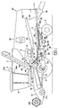
- the illustrated agricultural harvesting machine is a combine harvester of conventional design, using straw walkers, but it readily will be appreciated that the invention is equally applicable to the so-called rotary combines, such as the axial flow type combines.
- the invention also is applicable to other self-propelled harvesting machines, such as forage harvesters, potato harvesters, etc. Its use on a combine harvester should thus not be appraised as limiting.
- This combine harvester generally indicated at 1, comprises a main chassis or frame 2 supported on a front pair of drive wheels 3 and a rear pair of steerable wheels 4. Supported on the main chassis 2 are an operator's platform 5, with operator's cab 6, a grain tank 7, a first crop processing means, comprising a threshing and separating mechanism 8 and a grain cleaning mechanism 9, and a power plant or engine 10.
- a conventional header 11 and straw elevator 12 extend forwardly of the main chassis 2 and are pivotally secured to the chassis 2 for generally vertical movement which is controlled by extensible, single-acting hydraulic cylinders 13.
- the combine harvester 1 As the combine harvester 1 is propelled forwardly over a field with standing crop, the latter is severed from the stubble by a sickle bar 120 at the front of the header 11, whereafter the header 11 and the straw elevator 12 supply the cut crop to the threshing and separating mechanism 8.
- the crop received therein is threshed and separated, that is to say, the crop is rubbed and beaten, whereby the grain, seed or the like, is loosened and separated from the straw, coils or other discardable part of the crop.
- the combine harvester illustrated in Figures 1 and 2 comprises a conventional threshing and separation mechanism 8 including a threshing cylinder 14, a straw beater 16 and a separator rotor 18, cooperating with a set of concaves 19.
- Conventional straw walkers 20 are operable, in use, to discharge a mat of remaining crop material (i.e. mainly straw as the grain is separated therefrom) through a straw hood 21.
- a straw deflector plate 32 guides said mat to a second crop processing device which takes the form of a straw chopper 30.
- Grain which has been separated by the threshing and separating mechanism 8 falls onto a first grain pan 24 of the cleaning mechanism 9 which further also comprises a pre-cleaning sieve 26, positioned above a second grain pan 27, a pair of sieves 28, 29, disposed the one above the other, and a cleaning fan 25.
- the grain pans 24, 27 and the sieves 26, 28, 29 are oscillated generally back-and-forth for transporting threshed and separated grain from the first grain pan 24 to the pre-cleaning sieve 26 and the second grain pan 27 and therefrom to the sieves 28, 29.
- the same oscillatory movement spreads said grain across said sieves 26, 28, 29, while permitting the passage of cleaned grain by gravity through these sieves 26, 28, 29.
- the grain on the sieves 26, 28, 29 is subjected to a cleaning action by the fan 25 which provides an air flow through said sieves 26, 28, 29 to remove chaff and other impurities such as dust from the grain by making this material airborne for discharge from the machine through an outlet 22 of the straw hood 21.
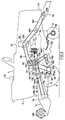
- Clean grain falls to a clean grain auger 35 in a clean grain auger trough 36 and is subsequently transferred therefrom to the grain tank 7.
- Tailings fall to a tailings auger (not shown) in a tailings auger trough 38.
- the tailings are transported sideways by said tailings auger to a separate rethresher 39 and returned to the cleaning mechanism 9 for repeated cleaning action.
- a grain tank auger 42 at the bottom of the grain tank 7 is used to urge the clean grain sideways to an unloading tube 43, wherein it is elevated by an unloading auger 44 for discharge from the harvester 1.
- the engine 10 is taking fuel from a fuel tank 50, in which is mounted a conventional fuel level sensor 51.
- the electrical resistance measured over this sensor is a function of the fuel level in the tank 50.
- the engine speed is controlled by a throttle 55 of a fuel injection system 53.
- the setting of said throttle 55 is determined by the spindle of an electrical engine speed actuator 56, which comprises a bidirectional electrical motor operable to vary the position of said spindle.
- the operator commands lowering or increasing of the engine speed through a switch 57 in a dashboard 100 in the cab 6.
- the actual engine speed is measured by means of an engine speed sensor 58, which is formed by a proximity sensor, operable to sense changes in magnetic field caused by a rotating part of the engine itself or by a part which is directly driven by the engine, such as the rotor of the alternator 54.
- the power from the engine is used to drive the wheels 3 by means of a main drive belt 60, which rotates a first variator sheave 62.
- This sheave 62 drives a second variator sheave 63 through a ground speed belt 61.
- the sheave 63 rotates the drive wheels 3 through a gearbox 67 and end drives (not shown).
- Said variator sheaves 62, 63 are composed of axially movable inner and outer halves, of which the relative position can be altered to change the run of the belt 61 and thus the transmission ratio of this drive.
- Such transmission system is well known in the art and has been described in further detail in EP-B-0.097.987.
- the relative position of the halves of the sheave 62 is controlled through an electrically controlled, hydraulic valve 65.
- the actual ground speed of the harvester 1 can be calculated from the number of revolutions of one of the gears in the gearbox 67.
- the speed of such gear equally is measured by a proximity sensor 70, which senses the changes in magnetic field, caused by the passing teeth of said gear.
- the operator commands the setting of said variator sheaves 62, 63 by means of a multifunctional handle 75 positioned next to an operator's seat 76.
- the pivoting movement of the handle 75 is mechanically transferred to a potentiometric device 80, over which a resistance is measured, which is representative for the wanted ground speed.
- the gearbox 67 can be driven by a conventional hydrostatic system, including a variable hydrostatic pump (not shown) mounted to the engine 10, and a hydrostatic motor fixed to said gearbox 67.
- the flow of hydrostatic oil in this system is governed by an electrically controlled servo valve 78, incorporated in said pump. The operator equally commands the ground speed through the said handle 75 and the potentiometric device 80.
- the drive wheels 3 can be slowed down and stopped by a hydraulic braking system, including two brakes 90 mounted on both sides of the gearbox 67.
- each one of said brakes 90 can be actuated separately by the fluid pressure from a master cylinder under action of one the foot pedals 85 at the operator's platform 5.
- This system permits blocking of one of the wheels 3, while the other still propels the harvester 1 in order to turn it with a small turning radius.
- the foot pedals 85 can be coupled by a linkage 87, of which the position is checked with a linkage sensor 88 in the form of a proximity sensor. Actuation of the brakes 90 is sensed through a brake sensor 86 including a switch which will be closed by the brake fluid pressure.
- a conventional differential mechanism in the gearbox 67 allows movement of the drive wheels 3 relative to each other. This mechanism is blocked by a hydraulic differential lock mechanism 95 upon actuation of an electrically controlled hydraulic valve 93 in order to impede said relative movement and to bring the wheels 3 into unitary movement. Engagement and disengagement of this blocking mechanism is commanded through a switch operated by differential lock pedal 94 at the operator's platform 5.
- the steerable wheels 4 are driven by hydrostatic motors 96, which are connected to the conventional hydrostatic system for the front wheel drive through an electrically controlled valve 97. Engagement and disengagement of this 4WD system is commanded by an ON/OFF switch 98 at the dashboard 100.
- the harvester 1 is equipped with a plurality of lights such as front and rear road lights 110 (only shown in Figure 10), stop lights 111 at the rear and a rotating light 112 on top of the harvester. These lights 110-112 are energized by a solid state power module 107.
- the road lights 110 are commanded through a switch (not shown) at a steering column 83 in the cab 6, the rotating light 112 through a switch 115 in the dashboard 100 and the stop lights 111 through the brake pressure sensor 86.
- the same power module 107 is used to energize a horn 113 underneath the operator's platform 5 upon pushing a switch at the steering column 83 in the cab 6.
- the height of the header 11 above the ground level is controlled by the single-acting hydraulic cylinders 13 which are connected to an electrically controlled, hydraulic valve 122. Lifting and lowering of the header are commanded through push buttons 123 in the multifunctional handle 75.
- the actual height of the header can be derived from the angle between operator's platform 5 and the straw elevator body 12. This angle is sensed by a variable resistor 125, whereof the body is fixed to the platform 5 and the movable core is held in contact with a notch lever 126 which is linked to the elevator 12.
- a header reel 128, which comprises six tines (not shown) is mounted for rotation on two pivotable arms 129 over a header frame 121.
- the position of the reel 128 needs adjustment to accommodate various crop conditions.
- a first pair of single-acting hydraulic cylinders 130 lifts or lowers the arms 129 and a second pair of double-acting hydraulic cylinders 131 moves the rotation shaft of the reel 128 forwards or backwards along said arms 129.
- the cylinders 130, 131 are controlled by two electrically controlled valves, 132 and 133 respectively. Both valves are incorporated in a valve block 200 at the side of the harvester 1.
- Vertical reel adjustment is commanded through the buttons 135 in the multifunctional handle 75 and horizontal adjustment is commanded through the foot switches 136 on the operator's platform 5.
- the reel 128 is rotated by a reel belt 138 which is driven by a sprocket and pulley assembly 139.
- This assembly is rotated through a chain 140 by a conventional variator arrangement comprising a driving sheave 143, a driven sheave 142 and a reel variator belt 144.
- the axially movable half of sheave 142 is held in position by a set of arms 146, which can be moved inwardly and outwardly by the spindle of an electrical motor 145 in order to change the run of belt 144 and hence the speed transmission ratio over this variator arrangement, whereby the reel speed, i.e. the relative speed of the reel tines to the header frame 121, is increased or lowered. Command of this speed adjustment is possible through push buttons 148 in said multifunctional handle 75.
- the sprocket of the assembly 139 is perforated along an inner diameter and a proximity sensor 148 is positioned at this diameter.
- the frequency of the pulses, generated in the sensor 148 by the passing perforations during rotation of the reel 128, is proportional to the reel speed, and thus is appropriate for the calculation of said speed.
- the first crop processing means comprising the threshing and separation mechanism 8 and the grain cleaning mechanism 9, and the header 11 are driven by sheaves on an intermediate shaft 150.
- Driving power to this shaft 150 is delivered by the engine 10 by means of the main drive belt 60 and a threshing engagement belt 152.
- An idler 154 can be pivoted to the front to release the tension on the belt 152, which then will get detached from its pulleys and cease its movement. Upon backward movement of the idler 154 the belt 152 is pushed into engagement again.
- the position of said idler 154 is controlled by a double-acting hydraulic cylinder (not shown), steered by an electrically controlled, hydraulic valve 156, which is incorporated in the valve block 200.
- Engagement of the first crop processing means is commanded by the operator by means of a threshing engagement ON/OFF switch 158 in the dashboard 100.
- the threshing cylinder 14 is driven by a second conventional variator arrangement comprising a driving sheave 160, a driven sheave 161 and a threshing variator belt 162.
- the axially movable half of sheave 161 is held in position by a set of arms 163, which can be moved inwardly and outwardly by the spindle of an electrical motor 164 in order to change the run of belt 162 and hence the speed transmission ratio over this variator arrangement, whereby the rotational speed of the threshing cylinder 14 is altered.
- the operator commands the speed adjustment by means of a monostable switch 166 at the dashboard 100.
- the actual drum speed is measured by a proximity sensor 168, which is mounted near and directed to the shaft of the threshing cylinder 14.
- the straw elevator 12 and header 11 are driven by a belt transmission comprising a header engagement belt 169 and a header drive belt 170.
- An idler 172 can be pivoted upwardly to release the tension on the belt 169, which then will get detached from its pulleys and cease its movement. Upon downward pivoting of the idler 172 the belt 169 is pushed back into engagement.
- the position of said idler 172 is controlled by a double-acting hydraulic cylinder 173, steered by an electrically controlled, hydraulic valve 174, which is incorporated in the valve block 200.
- Engagement of the straw elevator 12 and header 11 is commanded by the operator by means of a header engagement ON/OFF switch 176 in the dashboard 100.
- the grain cleaning mechanism 9 is driven by the intermediate shaft 150 through a belt 180.
- the same belt 180 is rotating the first sheave 181 of a fan variator arrangement, which further comprises a driven sheave 182 and a fan variator belt 183.
- the axially movable half of sheave 182 is held in position by a set of arms 184, which can be moved inwardly and outwardly by the spindle of an electrical motor 185 in order to change the run of belt 183 and hence the speed transmission ratio over this variator arrangement, whereby the rotational speed of the fan 25 is altered.
- the operator commands the fan speed adjustment by means of a monostable switch 187 at the dashboard 100.
- the actual fan speed is measured by a proximity sensor 189, which is mounted near and directed to the rotating shaft of the fan 25.
- the plates 193 and 194 sense the flow of lost grain at the outlet of the harvester 1 and are used as loss sensors.
- the plate 192 under the concaves receives grain from the very start of the threshing operation and is used as a threshing status sensor; its signal is proportional to the crop flow in the threshing and separation mechanism 9 and is reduced substantially when this mechanism 9 is running idle.
- Such detector plates have been described in detail in EP-B-0.339.140 and will not be discussed here any further.
- a switch is closed by the pressure of the grain on the surface of a grain level sensor 196.
- the signal from this sensor 196 is used to light one of the LEDs 198 of a warning lights module 101 in the dashboard 100.
- the position of the unloading tube 43 which is pivotally secured at the side of the grain tank 7, can be changed by means of a double-acting hydraulic cylinder 45, which is mounted between the operator's platform 5 and the lower end of said tube 43.
- the cylinder is steered through an electrically controlled valve 46, which is incorporated in the valve block 200.
- the changes in tube position are commanded through a monostable switch 48 in the dashboard 100.
- the rotor of straw chopper 30 is driven by the engine 10 through a belt transmission, comprising a front chopper belt 205, a chopper clutch assembly 206 and a rear chopper belt 207.
- the belts 205, 207 run over two sheaves of the clutch assembly 206, which further comprises an electromagnet which couples both sheaves when loaded, in order to rotate the straw chopper 30.
- Engagement of the clutch assembly 206 is commanded by an ON/OFF switch 210 at the dashboard 100.
- the speed of the rotor is sensed by a proximity sensor 209 near and directed to the rotating shaft of said rotor.
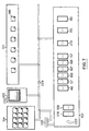
- the various settings of the machine are controlled by means of a communication network 300 which is generally depicted in Figure 6.
- the network 300 is a bi-directional single-channel network for the serial communication of digital data between microprocessor means 215, 218. These data are coded according to an advanced serial communications protocol with a very high level of security, such as the Controller Area Network (CAN) protocol, described in "CAN specification, Version 1.0", published in 1987 by Robert Bosch GmbH. According to this protocol interference of messages is prevented by giving to every message an initial, identifier portion, which indicates the type of the message and determines its relative priority.
- CAN Controller Area Network
- the microprocessor means 215, 218 keep receiving signals from said network 300, and when a higher priority message is detected, the lower priority message is truncated.
- This message is repeated automatically, when the higher priority message is finished.
- the messages are coded for detection of transmission errors.
- the identifier has a length of 11 bits a wide range of message types can be sent to the network.
- CAN enables effective communication between microprocessor units in a multi-master configuration, that is to say that no single microprocessor steers the whole network 300.
- the signals from and to the other electrical components, including command means, sensor means, machine actuator and display means, are collected or generated by electrical modules 101-109, 201-202, which comprise circuit boards and programmable microprocessor means 215, 218 for the automatic control of machine settings. These microprocessor means 215, 218 also transmit to and receive from the network 300 messages which are coded according to the CAN-protocol. Both the controlling and communicational functions can be integrated into one single chip.
- a microprocessor means 218 of this type is the Motorola chip 68HC705X4, which is installed in most of the modules 101-109, 201-202.
- a conventional, more powerful microprocessor 215 is installed and linked to a separate CAN chip 216 for communication of CAN-coded messages from and to the network 300.
- Such conventional microprocessor 215 is the Motorola chip 68HC11, which is installed in the display module 103. Network messages are encoded and decoded by the separate Philips CAN chip PCA 82C200.
- Transmitter-receiver units 217 make the connection with a wired portion 228 of the network 300.
- Every module 101-109, 201-202 is linked to the network 300 through its own microprocessor means 215, 218 and as the network communication according to the CAN protocol is not controlled by one single (master) microprocessor, there will be no obstruction to the data exchange between the other modules, when a microprocessor means 215, 218 of any module breaks down partially or completely.
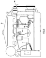
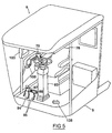
- the network 300 comprises three wired portions 228, which each comprise two electrical conductors. Each portion 228 interconnects modules which physically are located close to each other: a first portion 228 is linked to the modules 101-105 and 202, which are mounted in the cab 6; a second portion 228 to the modules 106 and 107 in a central box 240 below the grain tank 7; and a third portion 228 to the modules 108, 109 and 201 in a second box 241 near the engine 10.
- the modules 105, 106 and 108 each contain a second CAN-transmitter-receiver unit 217, which is linked to an optical transmitter 232, such as the SFH452V, and to an optical receiver 233, such as the SFH551V, both of Siemens.
- the optical signals pass through plastic optical fibres 231, which permit good data transmission over distances, such as those between the cab 6 and the boxes 240 and 241, and do not require the very strict precautions which are needed for the assembly of the more expensive and vulnerable glass optical fibre.
- Each module 105, 106, 108 is linked to an optical star module 230 by two fibres 231 of which one is connected to the optical transmitter 232, and the other to the optical receiver 233 of said modules.
- an active starpoint is formed by connecting an electrical circuit 234 to optical transmitters 232 and receivers 233.
- the incoming optical message from a module 105, 106, 108 is received at one of the star receivers 233 and transformed into an electrical signal, which is OR'd with the signals from the other modules by said circuit 234.
- the resulting logical OR signal is transferred to all optical star transmitters 232 and fed to the optical receivers 233 of the modules 105, 106 and 108.
- Such optical star network enables CAN transmission between a plurality of optical nodes and guarantees a sufficient power budget at all optical nodes.
- Passive star points which only divide the energy of incoming light pulses over a plurality of outgoing fibres, will need more powerful transmitters 232 at the modules 105, 106, 108 in order to obtain the same transmission quality.
- command means means, sensor means, machine actuator means and display means over a plurality of modules 101-109, 201
- machine actuator means By way of example a possible repartition of command means, sensor means, machine actuator means and display means over a plurality of modules 101-109, 201 will now be described in further detail.
- Figure 7 shows a set of modules which are mounted in and near the dashboard 100.
- the warning lights module 101 contains a plurality of LEDs 198, which are lighted by the microprocessor means 218 of said module 101 upon reception of hazardous condition messages from the network.
- hazardous condition messages include the high level of the grain in the grain tank 7, as detected by the sensor 96 or the anomalies in engine temperature and oil pressure.
- the dashboard switch module 102 collects the input signals from the command switches in the dashboard 100. These switches include the header engagement switch 176, the threshing engagement switch 158, the unloading tube switch 48, the engine speed switch 57, the drum speed switch 166, the fan speed switch 187, the straw chopper engagement switch 115 and the 4WD engagement switch 98. Additional switches are installed for the selection of a manual or automatic control mode of variables, such as a monostable fan memory selection switch 188 and a bistable reel speed mode switch 147. The dashboard module 102 also controls a low volume audible alarm in the form of a buzzer 223.
- the RPM status module 104 contains a plurality of LEDs which are lighted by the microprocessor means 218 of said module 104 when the actual RPM of a shaft, as communicated through the network 300, falls below a predetermined value that was set for that shaft. The operator thus is warned of excessive slippage or breakdown of one of the drivelines.
- the dashboard 100 equally contains a socket means 225 in the form of a conventional RS232 socket for serial communication to the network 300 and the other microprocessor means 215, 218.
- This connection to the network 300 is used to transmit and receive single data messages, but also to reprogram the microprocessor means 215, 218 of the other modules.
- the central display module 103 comprising a liquid crystal display 220, operable to communicate messages and graphs to the operator, a keyboard and microprocessor means 215 connected thereto, including a microprocessor unit and a permanent memory means (not shown) which is formed by a conventional EPROM or FLASH memory chip.
- Figure 8 is showing the arm rest module 202 comprising the multifunctional handle 75, with the push buttons for the command of header height (buttons 123), header reel height (buttons 135) and header reel speed (buttons 149).
- This module 202 further comprises the potentiometric device 80 of the ground speed command.
- the operator's platform module 105 incorporates the sensor and command means on the platform 5. These comprise: the brake pressure sensor 86, the brake linkage sensor 88, the differential lock command pedal 94, and the horizontal reel adjustment switches 136.
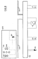
- Figure 9 is illustrating the sensor module 106 of the central box 240. It receives and processes signals from sensors, such as the grain tank level sensor 196, the reel speed sensor 148, the drum speed sensor 168, the ground speed sensor 70, the fan speed sensor 189, the sieve impact sensor 194 and the header height sensor 125.
- sensors such as the grain tank level sensor 196, the reel speed sensor 148, the drum speed sensor 168, the ground speed sensor 70, the fan speed sensor 189, the sieve impact sensor 194 and the header height sensor 125.
- the power module 107 of Figure 10 is equally mounted in said central box 240. It comprises a solid state power module for the supply of tension and power to electrical consumers such as the motor 145 of the reel speed variator arrangement, the horn 113, the motor 164 of the threshing speed variator arrangement, the motor 185 of the fan speed variator arrangement, the solenoids of the header height adjustment valve 122, the stop lights 111, the rotating light 112 and the front and rear lights 110.
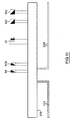
- Figure 11 shows the sensor module 108 of the engine box 241. It receives and processes signals from a second group of sensors, such as the engine speed sensor 58, the straw chopper speed sensor 209, the fuel level sensor 51, the concave impact sensor 192 and the straw walker impact sensor 193.
- a second group of sensors such as the engine speed sensor 58, the straw chopper speed sensor 209, the fuel level sensor 51, the concave impact sensor 192 and the straw walker impact sensor 193.
- Figure 12 illustrates the power module 109 of the engine box 241. It provides tension and power to further actuators, such as the engine speed actuator 56, the straw chopper clutch 206, the solenoid of the 4WD valve 97 and the solenoids of the ground speed variator valve 65 or, alternatively, the servo valve 78 of the hydrostatic drive.
- further actuators such as the engine speed actuator 56, the straw chopper clutch 206, the solenoid of the 4WD valve 97 and the solenoids of the ground speed variator valve 65 or, alternatively, the servo valve 78 of the hydrostatic drive.
- valve module 201 which controls the solenoids in valve block 200, which module equally is installed in said box 241. It provides power to the solenoids of the header engagement valve 174, the threshing engagement valve 156, the unloading tube valve 46, the horizontal reel adjustment valve 132, the vertical reel adjustment valve 133 and the differential lock valve 93.
- the stop lights 111 are activated when the brake pedals 85 are depressed. This action is sensed by the brake pressure sensor 86 which then closes an electrical circuit to the stop lights 111.
- the stop lights 111 are lighted by the solid state power module 107 of the central box 240.
- the microprocessor means 218 of this module 107 provides power to the lights 111 upon detection of a wider range of machine conditions, which all correspond to a slowing down of the harvester 1.
- the lights 111 thus are activated when the actual ground speed as sensed by the sensor 70, is decreasing at a rate which exceeds a predetermined amount. The rate of speed decrease is calculated from the ground speed messages by the microprocessor means 218 of the module 107.
- the lights 111 also can be activated when the setting of the ground speed command potentiometer 80 is changed to slow down the machine 1.
- the decrease of the wanted ground speed can equally be detected by the said microprocessor means 218, if it checks the value of the wanted speed at regular intervals.
- These processes can be combined all together in order to light the stop lights 111 at any of said conditions, i.e. brake pressure, ground speed decrease and ground speed decrease command.
- Other road users riding behind a harvester thus under all circumstances are timely warned of harvester slowing down, even in the case that no brake pedal 85 is used, but another means, e.g. the hydrostatic drive, is used to stop the vehicle.
- the module and network configuration permits this limitation in a non-mechanical way: via the RS232 socket means 225 data on wheel size, destination and maximum speed can be transmitted for storage in the microprocessor means 218 of the engine power module 109, which controls the speed actuator means, such as the servo valve 78 of the hydrostatic drive or the hydraulic valve 65 of the variator drive; the actual ground speed as sensed by the ground speed sensor 70 is transmitted to the said microprocessor means 218 for comparison; when this speed reaches said maximum speed, the microprocessor means 218 will disregard any further speed increase commands and thus halt the speed actuator means at the said maximum speed.
- the microprocessor means 218 via the RS232 socket means 225 data on wheel size, destination and maximum speed can be transmitted for storage in the microprocessor means 218 of the engine power module 109, which controls the speed actuator means, such as the servo valve 78 of the hydrostatic drive or the hydraulic valve 65 of the variator drive; the actual ground speed as sensed by the ground speed sensor 70 is transmitted to the said microprocessor means 2
- the comparison can take place in the arm rest module 202 and its microprocessor means 218, which is linked to the ground speed command 80, can stop the transmission of a speed increase command to the network 300, when the maximum speed is reached.
- a harvester 1 is equipped with other wheels or reallocated to a country with different speed limits, it suffices to load new data in the network via the socket 225 in order to set the speed limits to other values.
- the rotating light 112 also can be used as a warning means to people near the harvester 1 during backward travel.
- the microprocessor means 218 of the power module 107 activates the light 112.
- the light 112 can be activated by the same module 107 when backward travel is commanded through the ground speed command 80.
- a short blow of the horn 113 is given at the beginning of the backward travel. The operator can do this by pushing the switch at the steering column 83, but the horn 113 is also activated automatically by the microprocessor means 218 of the power module 107, when an actual reverse speed or a reverse speed command message is received.
- the microprocessor means 218 of the power module 107 activates the light 112 for a predetermined time interval. The operator thus does not have to direct his attention to the grain tank level and can concentrate on the other harvesting operations.
- the use of the Four Wheel Drive system is only recommended at low speed, off-road harvesting operations.
- the microprocessor means 218 of the power module 109 only controls the valve 97 in order to provide driving power to the steerable wheels 4 when the ground speed, as sensed by the ground speed sensor 70, falls below a low predetermined speed, and to cut this power when the sensed ground speed raises above a high predetermined speed.
- the use of the 4WD thus automatically is limited to optimum conditions.
- the differential lock in the gearbox 67 can get damaged when engaged or disengaged at high ground speed. Therefore, the microprocessor means 218 of the valve module 201 ignores any engagement or disengagement commands from the differential lock pedal 94 as long as the ground speed remains above a predetermined high speed. When the ground speed falls below said high speed, the valve module 201 resets the differential lock valve 133 back to the commanded condition. This process is protecting the differential lock system from hazardous setting changes.
- the signal from the fuel level sensor 51 is used to display a wide range of data to the operator.
- the microprocessor means 215 of the display module 103 can put the fuel level on the display 220. It also combines these data with the lapsed time or the covered distance, which can be derived from the ground speed sensor 70 messages, in order to calculate the actual and average fuel consumption rate per hour or per kilometre.
- the microprocessor means 215 When the fuel quantity falls to the level of one hour's operation at average fuel consumption rate, the microprocessor means 215 generates a warning message on the display 220. The operator thus learns he has to refill within a short period of time.
- Actuation of a single brake is useful during harvesting operations, but is hazardous during road travel. Therefore the brake pedals 85 must be linked when the harvester 1 is using the road, but this linkage is not visible at first sight.
- the microprocessor means 218 of the dashboard module 102 is programmed to sound the buzzer 223 when on the one hand the brake linkage sensor 88 senses no coupling of the pedals 85, and on the other hand the ground speed is raising above a predetermined level. Simultaneously a LED 198 is be lighted by the microprocessor means 218 of the warning lights module 101 and a warning message is displayed by the microprocessor means 215 of the display module 103. The attention of the operator thus is immediately drawn to the hazardous condition.
- the reel speed mode switch 147 is used to select a 'manual' or an 'automatic' mode for reel speed adjustment.
- the microprocessor means 218 of the power module 107 actuates the reel variator motor 145 in order to vary the reel speed in accordance with the commands given by means of the push buttons 149 of the multifunctional handle 75.
- the said microprocessor means 218 actuates the motor 145 in order to adapt the reel speed to the actual value of the ground speed as sensed by the sensor 70: the reel speed is adjusted until the difference between reel speed and ground speed meets a substantially constant value. Standing crop thus is bent over to the header 11 in a constant fashion, irrespective of the ground speed of the harvester 1.
- the actual reel speed is detected by the sensor 148 and the microprocessor means 218 of the sensor module 106 transmits its value to the network 300, so that it can be used for feedback by the microprocessor means 218 of the modules 107 in the reel adjustment process.
- the motor 185 of the fan speed variator is actuated by power module 107 to change the fan speed as commanded by the fan speed switch 187.
- the actual fan speed is sensed by the sensor 189 and its value is transmitted to the network 300 by the sensor module 106 and displayed to the operator by the module 103.
- the selection switch 188 is pushed up for a longer time, e.g. for more than three seconds, the actual fan speed is stored in a first memory of the microprocessor means 218 of the power module 107 and when the switch 188 is pushed down for a longer time, it is stored in a second memory of the same microprocessor means 218.
- the said microprocessor means 218 compares the actual fan speed value to the value in the first memory and steers the power module 107 to adjust the fan speed to this value. In a similar way the fan speed is adjusted to the value in the second memory, when the switch 188 is pushed down for a shorter time. The operator thus is able to change the fan speed by a simple pulse command.
- an inclination sensor (not shown) may be installed on the harvester 1 for measurement of the field slope in the direction of harvester movement.
- the signal from this sensor then can be used by the microprocessor means 218 of module 107 for the choice of one of said fan speed memories and adjustment of the fan speed to the value stored therein.
- the operator sets the fan speed manually to a first value during downhill travel, stores it in the first memory, sets the speed to second value during uphill travel and stores it in the second memory, whereafter the fan speed is switched automatically between these values every time the inclination sensor feels a transition from uphill to downhill travel and vice versa.
- the microprocessor means 218 of valve module 201 When the threshing engagement switch 158 is set to ON (and it thus may supposed that the harvester is standing in the open), and the operator gives a pulse command on the switch 48 to change the position of the unloading tube 43, the microprocessor means 218 of valve module 201 accordingly activates one of the solenoids of valve 46 to extend or retract the cylinder 45, until the operator gives an opposite pulse command on the switch 48, by which action the valve 46 is deactivated and the cylinder 45 is stopped. On the other hand, when the switch 158 is set to OFF, the microprocessor means 218 of module 201 stops all activation of the valve 46 as soon as the switch 48 is released. This second command mode is useful during servicing in buildings, where the tube 43 otherwise might hit walls or supports when completely pivoted.
- the microprocessor means 218 of the engine power module 109 Upon switching the threshing engagement switch 158 from OFF to ON, the microprocessor means 218 of the engine power module 109 first makes actuator 56 reduce the engine speed, before the valve module 101 puts an electrical tension over the engagement valve 156. After the engagement of the threshing mechanism 8 the power module 109 makes the engine 10 resume its original speed. Switching the straw chopper engagement switch 210 from OFF to ON has the same effect on the control of the engine speed. This process reduces the stress on the drive belts 60, 205 during the engagement of the crop processing means.
- the microprocessor means 218 of the engine power module 109 actuates the servo valve 78 of the hydrostatic drive or the valve 65 of the variator drive in order to reduce the ground speed and thus the flow of crop material to the harvester 1, until the sieve losses have reached an predetermined, acceptable level.
- the ground speed thus is adjusted automatically to the crop conditions.
- the operator turns it on a portion of the field which is free of crop, the so-called head land.
- the head land is detected by the impact sensor 192 under the concaves 19, in as much as, upon entering the head land, the threshing and separation mechanism 8 no longer are fed with crop.
- a wide range of machine settings is automatically set to predetermined, standard conditions. These conditions can be changed and loaded in the memories of the various microprocessor means 215, 218 via the RS232 socket means 225 or via the command means, such as the keyboard of the display module 103.
- the said machine settings comprise the height of the header 11, the speed of the fan 25 and the speed of the reel 128, which are controlled by the microprocessor means 218 of power module 107.
- the reel speed is set to a predetermined speed, or alternatively, the automatic adjustment of the reel speed to the ground speed is switched on.
- the settings further comprise the horizontal and vertical positions of said reel 128, which are controlled by the microprocessor means 218 of valve module 201. Upon detection of the headland, the automatic control of the ground speed in accordance with the grain losses is disabled by the microprocessor means 218 of power module 109.
- the harvester When the harvester is modified by adding features such as the 4WD or the straw chopper 30, there is no need for extensive rewiring. It suffices to link the electrical connections to the nearby modules and to pass an adapted program via the RS232 socket means 225 to the microprocessor means 215, 218 of said modules. Alternatively, the microprocessor means 218 can be programmed to check whether a feature is present and to select a control routine accordingly. Thus is offered a large flexibility for modification of the harvester features.
- the microprocessor means 215, 218 have the possibility to detect abnormal conditions such as a short-circuit, a broken connection or a faulty actuator. When such conditions are established the microprocessor transmits an error message to the network 300.
- the display module 103 warns the operator by means of a warning text on the display 220, and the other microprocessor means 215, 218 switch to alternative routines or use default values in order to by-pass the faulty component if possible. Thus is enhanced the total reliability of the whole harvester 1.
- the described process for the control of agricultural harvester can further be refined by the addition of other sensor, command and actuator means or by loading other control programs into the modules, without departing from the original idea of the invention. It also is easily applicable to other self-propelled harvesting machines such as e.g. forage harvesters and potato harvesters.
Claims (14)
- Machine de récolte agricole (1) comprenant :un moteur (10) et un reservoir (50) à carburant equipés d'un capteur de carburant (51) générant un signal correspondant au niveau du carburant dans ledit reservoir (50);des moyens de processeurs programmables (215, 218) actionnables de manière à recevoir des signaux d'entrée des capteurs d'état de la machine et/ou d'un réseau de communication et/ou de moyens de commande de la machine et pour générer des signaux de sortie afin d'afficher des moyens (220) et/ou ledit réseau de communication et/ou des moyens d'actionneurs mécaniques,lesdits moyens de microprocesseurs (215, 218) étant actionnables de manière à recevoir le signal d'entrée dudit capteur (51) de carburant et à calculer la quantité de carburant à partir dudit signal du capteur de carburant,caractérisée en ce que lesdits moyens de microprocesseurs (215, 218) :calculent également la consommation de carburant moyenne à partir dudit signal du capteur de carburant; etgénèrent également un signal de sortie pour le moment où la quantité de carburant calculée retombera à zéro dans un délai prédéfini.
- Machine de récolte agricole selon la revendication 1, caractérisée en ce que ledit signal de sortie entraîne l'affichage d'un message d'avertissement par lesdits moyens d'affichage (220).
- Machine de récolte agricole selon la revendication 1 ou 2, caractérisée en ce que ladite période prédéterminée est égale à une heure pour l'essentiel.
- Machine de récolte agricole selon l'une quelconque des revendications précédentes, caractérisée en ce que que lesdits moyens de microprocesseurs (215, 218) calculent le niveau de consummation moyen du carburant à l'heure ou au kilomètre.
- Machine de récolte agricole selon l'une quelconque des revendications précédentes, caractérisée en ce que lesdits moyens de microprocesseurs (215) placent le niveau de carburant sur les moyens d'affichage (220).
- Machine de récolte agricole selon l'une quelconque des revendications précédentes, caractérisée en ce que :lesdits moyens de microprocesseurs comprennent une pluralité de microprocesseurs (215, 218) reliés entre eux par un réseau à canal unique pour la communication sérielle de messages de données numériques qui possèdent une partie initiale pour l'identification du type de message et la détermination de leurs priorités relatives etledit réseau (300) est relié auxdits microprocesseurs (215, 218) par des unités émétrices/réceptrices (217).
- Machine de récolte agricole selon la revendication 6, caractérisée en ce que ledit réseau (300) comprend un réseau de transmission optique (230, 231).
- Machine de récolte agricole selon la revendications 6, caractérisée en ce que ledit réseau de transmission optique comprend un réseau en étoile (230, 231) comprenant un point en étoile passif ou actif (230).
- Machine de récolte agricole selon la revendication 7 ou 8, caractérisée en ce que ledit réseau de transmission optique comprend des fibres optiques plastiques (231).
- Machine de récolte agricole selon l'une quelconque des revendications 6 à 9, caractérisée en ce que les moyens de microprocesseurs (215, 218) recoivent des signaux d'entrée d'une commande de regime du moteur (57) et génèrent des signaux de sortie en direction d'un actionneur de régime du moteur (56) qui peut être utilisé pour modifier le réglage dudit régime.
- Machine de récolte agricole selon la revendication 10, caractérisée en ce que ledit actionneur de regime (56) comprend une broche à commande életcrique qui est reliée à un niveau de commande du régime.
- Machine de récolte agricole selon l'une quelconque des revendications précédentes, caractérisée en ce que lesdits détecteurs d'état comprennent un détecteur de vitesse du moteur (58) dotn le signal correspond à la vitesse de rotation réelle dudit moteur (10).
- Machine de récolte agricole selon l'une quelconque des revendications précédentes, caractérisée en ce que lesdits moyens de micorprocesseurs (215, 218) sont programmables via le réseau (300).
- Machine de récolte agricole selon la revendication 13, caractérisée en ce que les moyens de microprocesseurs (215, 218) sont programmables par des moyens de prise (225) reliées au réseau (300).
Priority Applications (2)
| Application Number | Priority Date | Filing Date | Title |
|---|---|---|---|
| EP97200496A EP0787978B1 (fr) | 1993-06-28 | 1993-06-28 | Moissonneuse agricole autopropulsée |
| DE1993634104 DE69334104T2 (de) | 1993-06-28 | 1993-06-28 | Selbstfahrende landwirtschaftliche Erntemaschine |
Applications Claiming Priority (2)
| Application Number | Priority Date | Filing Date | Title |
|---|---|---|---|
| EP97200496A EP0787978B1 (fr) | 1993-06-28 | 1993-06-28 | Moissonneuse agricole autopropulsée |
| EP93201879A EP0631906B2 (fr) | 1993-06-28 | 1993-06-28 | Procédé de commande pour moissonneuses agricoles autopropulsées |
Related Parent Applications (2)
| Application Number | Title | Priority Date | Filing Date |
|---|---|---|---|
| EP93201879A Division EP0631906B2 (fr) | 1993-06-28 | 1993-06-28 | Procédé de commande pour moissonneuses agricoles autopropulsées |
| EP93201879.9 Division | 1993-06-28 |
Publications (3)
| Publication Number | Publication Date |
|---|---|
| EP0787978A2 EP0787978A2 (fr) | 1997-08-06 |
| EP0787978A3 EP0787978A3 (fr) | 1998-07-08 |
| EP0787978B1 true EP0787978B1 (fr) | 2007-01-17 |
Family
ID=8213933
Family Applications (6)
| Application Number | Title | Priority Date | Filing Date |
|---|---|---|---|
| EP19970200495 Withdrawn EP0779201A2 (fr) | 1993-06-28 | 1993-06-28 | Véhicule utilitaire |
| EP97200477A Withdrawn EP0774383A3 (fr) | 1993-06-28 | 1993-06-28 | Procédé de commande pour une moissonneuse auto-propulsée |
| EP93201879A Expired - Lifetime EP0631906B2 (fr) | 1993-06-28 | 1993-06-28 | Procédé de commande pour moissonneuses agricoles autopropulsées |
| EP97200497A Withdrawn EP0777960A3 (fr) | 1993-06-28 | 1993-06-28 | Procédé de commande pour moissonneuses autopropulsées |
| EP97200478A Expired - Lifetime EP0775612B1 (fr) | 1993-06-28 | 1993-06-28 | Procédé de commande pour une moissonneuse auto-propulsée |
| EP97200496A Expired - Lifetime EP0787978B1 (fr) | 1993-06-28 | 1993-06-28 | Moissonneuse agricole autopropulsée |
Family Applications Before (5)
| Application Number | Title | Priority Date | Filing Date |
|---|---|---|---|
| EP19970200495 Withdrawn EP0779201A2 (fr) | 1993-06-28 | 1993-06-28 | Véhicule utilitaire |
| EP97200477A Withdrawn EP0774383A3 (fr) | 1993-06-28 | 1993-06-28 | Procédé de commande pour une moissonneuse auto-propulsée |
| EP93201879A Expired - Lifetime EP0631906B2 (fr) | 1993-06-28 | 1993-06-28 | Procédé de commande pour moissonneuses agricoles autopropulsées |
| EP97200497A Withdrawn EP0777960A3 (fr) | 1993-06-28 | 1993-06-28 | Procédé de commande pour moissonneuses autopropulsées |
| EP97200478A Expired - Lifetime EP0775612B1 (fr) | 1993-06-28 | 1993-06-28 | Procédé de commande pour une moissonneuse auto-propulsée |
Country Status (3)
| Country | Link |
|---|---|
| US (1) | US5488817A (fr) |
| EP (6) | EP0779201A2 (fr) |
| DE (1) | DE69314330T3 (fr) |
Cited By (1)
| Publication number | Priority date | Publication date | Assignee | Title |
|---|---|---|---|---|
| RU2482654C2 (ru) * | 2007-09-27 | 2013-05-27 | КЛААС Зельбстфаренде Эрнтемашинен ГмбХ | Способ управления рабочей сельхозмашиной |
Families Citing this family (138)
| Publication number | Priority date | Publication date | Assignee | Title |
|---|---|---|---|---|
| DE4341834C1 (de) * | 1993-12-08 | 1995-04-20 | Claas Ohg | Landmaschine, insbesondere Mähdrescher, mit Multiprozessor-Leitvorrichtung |
| CA2141092C (fr) * | 1995-01-25 | 1999-01-05 | James F. White | Communications entre les elements d'une machine |
| DE19508942A1 (de) * | 1995-03-13 | 1996-09-19 | Claas Ohg | Reflex-Ortungsvorrichtung |
| DE19514223B4 (de) * | 1995-04-15 | 2005-06-23 | Claas Kgaa Mbh | Verfahren zur Einsatzoptimierung von Landmaschinen |
| FR2744813A1 (fr) * | 1996-02-09 | 1997-08-14 | Plantevignes Patrice | Systeme de transmission de donnees entre un reseau d'automates de fonctions domestiques et une unite centrale de commande de ces automates |
| DE19623754A1 (de) * | 1996-06-14 | 1997-12-18 | Claas Ohg | Erntemaschine mit einem in seiner Arbeitslage gegenüber dem Boden höhenverstellbaren Vorsatzbearbeitungsgerät |
| US6070538A (en) * | 1996-11-22 | 2000-06-06 | Case Corporation | Modular agricultural implement control system |
| US5924371A (en) * | 1997-09-23 | 1999-07-20 | Case Corporation | Global controller and distributed local controller(s) for an agricultural implement |
| US6024035A (en) * | 1997-09-23 | 2000-02-15 | Case Corporation | Seed planting rate maintenance control with rate display |
| US6091997A (en) * | 1997-09-23 | 2000-07-18 | Case Corporation | Enhanced statistical/status display |
| US5956255A (en) * | 1997-09-23 | 1999-09-21 | Case Corporation | Seed planter performance monitor |
| US6009354A (en) * | 1997-09-23 | 1999-12-28 | Case Corporation | Enhanced implement control |
| US6337971B1 (en) * | 1997-10-14 | 2002-01-08 | Gerald L. Abts | System for controlling and monitoring agricultural field equipment and method |
| DE19800238C1 (de) * | 1998-01-07 | 1999-08-26 | Claas Selbstfahr Erntemasch | System zur Einstellung einer selbstfahrenden Erntemaschine |
| US6003455A (en) * | 1998-03-05 | 1999-12-21 | Case Corporation | Regulator control |
| US5878557A (en) * | 1998-04-13 | 1999-03-09 | Deere & Company | Derating the engine of a combine in response to usage |
| DE19844894A1 (de) * | 1998-09-30 | 2000-04-06 | Claas Selbstfahr Erntemasch | Verstelleinrichtung einer landwirtschaftlichen Erntemaschine |
| US6119442A (en) * | 1999-05-14 | 2000-09-19 | Case Corporation | Combine setting autoadjust with machine vision |
| US6431981B1 (en) | 1999-06-30 | 2002-08-13 | Wisconsin Alumni Research Foundation | Yield monitor for forage crops |
| US6282476B1 (en) | 1999-07-22 | 2001-08-28 | Claas Ohg | Agricultural machine, in particular a combine harvester and thresher, with multi-processor master unit |
| GB2356546A (en) | 1999-11-26 | 2001-05-30 | Ford New Holland Nv | Threshing and separating unit for axial flow combines |
| FR2805122B1 (fr) * | 2000-02-22 | 2003-01-24 | Jean Paul Courrier | Procede de pilotage electronique d'une moissonneuse-batteuse a commande hydraulique |
| GB0005178D0 (en) * | 2000-03-06 | 2000-04-26 | Ford New Holland Nv | Feeder controls for a forage harvester |
| DE50009354D1 (de) * | 2000-05-03 | 2005-03-03 | Voegele Ag J | Computerisiertes Steuersystem |
| DE10030473A1 (de) * | 2000-06-21 | 2002-01-03 | Deere & Co | Eingabeeinrichtung einer Arbeitsmaschine |
| DE10057135A1 (de) * | 2000-11-17 | 2002-05-23 | Deere & Co | Stelleinrichtung eines Aufnehmers für Erntegut |
| DE10105858A1 (de) | 2001-02-08 | 2002-08-14 | Deere & Co | Kommunikationssystem eines Fahrzeugs |
| ITBO20010108A1 (it) * | 2001-02-28 | 2002-08-28 | Azionaria Costruzioni Automati | Macchina per il riempimento di contenitori |
| DE10109775A1 (de) | 2001-03-01 | 2002-09-12 | Deere & Co | Antriebssystem eines Arbeitsfahrzeugs |
| US6487836B1 (en) | 2001-03-20 | 2002-12-03 | Deere & Company | Crop moisture sensor for controlling harvesting speed |
| US6951514B1 (en) * | 2001-03-20 | 2005-10-04 | Deere & Company | Throughput control for combines using feederhouse signal |
| US6475081B2 (en) | 2001-03-20 | 2002-11-05 | Deere & Company | Throughput control for combines having a variable torque sensing drive |
| US6830061B2 (en) * | 2001-04-27 | 2004-12-14 | Fisher Controls International Llc | Intelligent regulator with input/output capabilities |
| US6591591B2 (en) * | 2001-07-30 | 2003-07-15 | Deere & Company | Harvester speed control with header position input |
| US6592453B2 (en) * | 2001-09-27 | 2003-07-15 | Deere & Company | Harvester feedrate control with tilt compensation |
| US6655351B2 (en) | 2001-10-24 | 2003-12-02 | Deere & Company | Vehicle engine control |
| US6587771B2 (en) | 2001-11-15 | 2003-07-01 | Case Corporation | Variable feeder and header drive system for an agricultural harvesting machine |
| US6775966B2 (en) * | 2001-12-18 | 2004-08-17 | New Holland North America, Inc. | Integrated combine reel drive system |
| US6882918B2 (en) * | 2001-12-27 | 2005-04-19 | Caterpillar Inc | Electric drive management system and method |
| US6865870B2 (en) * | 2002-01-10 | 2005-03-15 | Cnh America Llc | Combine power selection system |
| BR0200591C1 (pt) * | 2002-02-22 | 2003-04-08 | Jacto Maquinas Agricolas | Desenvolvimento em processo e em dispositivo de posicionamento relativo entre máquinas agrìcolas e culturas em suas linhas de plantio |
| US6726559B2 (en) * | 2002-05-14 | 2004-04-27 | Deere & Company | Harvester with control system considering operator feedback |
| DE10245885A1 (de) * | 2002-09-30 | 2004-04-08 | Deere & Company, Moline | Erntemaschine |
| DE10327758A1 (de) * | 2003-06-18 | 2005-01-05 | Claas Selbstfahrende Erntemaschinen Gmbh | Verfahren zur Steuerung eines Dreschwerks eines Mähdreschers |
| JP2005016436A (ja) * | 2003-06-26 | 2005-01-20 | Honda Motor Co Ltd | 芝刈り機用エンジンの回転数制御装置 |
| US7788892B2 (en) * | 2003-07-10 | 2010-09-07 | Deere & Company | User interface and control for cutting reel system |
| DE10348090A1 (de) * | 2003-10-16 | 2005-05-19 | Deere & Company, Moline | Landwirtschaftliche Arbeitsmaschine |
| US6984172B2 (en) * | 2004-01-14 | 2006-01-10 | Cnh America Llc | Dual power path drive for a rotating threshing rotor of an agricultural combine and method for decelerating the rotor |
| DE102004013287B4 (de) * | 2004-03-18 | 2006-07-06 | Maschinenfabrik Bernard Krone Gmbh | Erntemaschine |
| US7386380B2 (en) * | 2006-07-31 | 2008-06-10 | Deere & Company | Cotton harvester row unit speed synchronization control |
| US20080034720A1 (en) * | 2006-08-11 | 2008-02-14 | Helfrich James C | Engine load control for hydrostaticaly driven equipment |
| DE102006045789A1 (de) * | 2006-09-26 | 2008-06-26 | Claas Selbstfahrende Erntemaschinen Gmbh | Antriebseinrichtung für Mähdrescher |
| JP4798374B2 (ja) * | 2006-09-29 | 2011-10-19 | 株式会社エクォス・リサーチ | 走行車両 |
| CN101529820B (zh) * | 2006-11-03 | 2013-06-19 | 索尤若驱动有限及两合公司 | 用于总线仲裁的方法和装置、变频器和加工设备 |
| DE102007004576A1 (de) * | 2007-01-24 | 2008-07-31 | Claas Selbstfahrende Erntemaschinen Gmbh | Landwirtschaftliche Arbeitsmaschine |
| AR060425A1 (es) * | 2007-04-11 | 2008-06-18 | Consejo Nac Invest Cient Tec | Metodo para disminuir perdidas por cola en la cosecha de granos y dispositivo regulador de la velocidad de avance de una cosechadora |
| DE102007029218A1 (de) * | 2007-06-22 | 2008-12-24 | Claas Selbstfahrende Erntemaschinen Gmbh | Selbstfahrende landwirtschaftliche Erntemaschine mit Verlustmesseinrichtung |
| DE102007055074A1 (de) * | 2007-11-16 | 2009-05-20 | Claas Selbstfahrende Erntemaschinen Gmbh | Selbstfahrende landwirtschaftliche Arbeitsmaschine |
| US8074433B2 (en) * | 2008-03-14 | 2011-12-13 | Deere & Company | Agricultural harvester with auxiliary power unit and intelligent power management |
| US7992370B2 (en) * | 2008-03-14 | 2011-08-09 | Deere & Company | Work machine with auxiliary power unit and intelligent power management |
| DE102008043716B4 (de) * | 2008-11-13 | 2012-06-21 | Deere & Company | Vorrichtung und Verfahren zur Erfassung der Bestandsdichte von Pflanzen auf einem Feld |
| GB2466065A (en) * | 2008-12-12 | 2010-06-16 | Agco Gmbh | Braking system having left and right brake pedals that are lockable together, and warning means to indicate the pedals are unlocked |
| GB2466066A (en) * | 2008-12-12 | 2010-06-16 | Agco Gmbh | Braking system having left and right brake pedals that are lockable together, and warning means to indicate the pedals are unlocked |
| US8209095B2 (en) * | 2009-05-11 | 2012-06-26 | Deere & Company | Agricultural harvester with dual engines and power sharing based on engine temperature |
| US7866132B2 (en) * | 2009-05-20 | 2011-01-11 | Deere & Company | Harvesting head reel support arrangement including hydraulic cylinders and control circuitry |
| JP4766160B2 (ja) * | 2009-07-29 | 2011-09-07 | 株式会社デンソー | 通信システムおよび通信ノード |
| US8010262B2 (en) * | 2009-10-21 | 2011-08-30 | Cnh America Llc | Apparatus and method for automatically controlling the settings of an adjustable crop residue spreader of an agricultural combine |
| DE102011054096A1 (de) * | 2011-09-30 | 2013-04-04 | Claas Selbstfahrende Erntemaschinen Gmbh | Antriebsvorrichtung für eine aus einem Erntevorsatz und/oder einem Schrägförderer bestehende Baugruppe einer selbstfahrenden Erntemaschine |
| DE102011121945B4 (de) * | 2011-12-22 | 2016-08-11 | Johannes Hoeck | Selbstfahrender Mähdrescher |
| DE102013201618A1 (de) * | 2013-01-31 | 2014-07-31 | Deere & Company | Schwingungsaufnehmereinheit |
| CN103336461B (zh) * | 2013-06-06 | 2015-06-17 | 山西省农业机械质量监督管理站 | 稻麦联合收割机试验检测接样装置控制系统 |
| ITMI20131050A1 (it) * | 2013-06-24 | 2014-12-25 | Roter Italia S R L | Dispositivo per la prevenzione dei guasti nei meccanismi lubrificati ad immersione, in particolare nelle macchine agricole |
| US9699970B2 (en) * | 2013-09-19 | 2017-07-11 | Cnh Industrial America Llc | Combine side-shake cleaning control system |
| US20150234767A1 (en) | 2013-09-23 | 2015-08-20 | Farmobile, Llc | Farming data collection and exchange system |
| US10352743B1 (en) * | 2013-09-26 | 2019-07-16 | Sensors That Count, L.L.C. | Flow sensor based on electrical capacity |
| US11231305B2 (en) * | 2013-09-26 | 2022-01-25 | Amvac Chemical Corporation | Flow sensor apparatus for monitoring a directed stream of an agricultural product |
| DE102013112184A1 (de) * | 2013-11-06 | 2015-05-07 | Horsch Leeb Application Systems Gmbh | Verfahren und Vorrichtung zur Steuerung einer Fahrgeschwindigkeit einer landwirtschaftlichen Maschine |
| JP6396724B2 (ja) * | 2013-12-03 | 2018-09-26 | 株式会社クボタ | コンバイン |
| JP6257480B2 (ja) * | 2014-09-02 | 2018-01-10 | 株式会社クボタ | 収穫機 |
| DE102014113008A1 (de) * | 2014-09-10 | 2016-03-10 | Claas Selbstfahrende Erntemaschinen Gmbh | Verfahren zum Betreiben eines Mähdreschers |
| USD971089S1 (en) | 2015-04-03 | 2022-11-29 | Warn Automotive, Llc | Motorized disconnect assembly |
| BE1022889B1 (nl) * | 2015-05-29 | 2016-10-07 | Cnh Industrial Belgium Nv | controller voor een oogstmachine |
| US10188039B2 (en) * | 2015-09-30 | 2019-01-29 | Deere & Company | Electrical power generation for header systems from a combine backshaft |
| JP6637832B2 (ja) * | 2016-04-28 | 2020-01-29 | 株式会社クボタ | 収穫機 |
| CN106561172B (zh) * | 2016-10-25 | 2019-01-08 | 江苏大学 | 一种纵轴流联合收获机排草粉碎自适应抛撒装置及其控制方法 |
| GB2561868A (en) * | 2017-04-26 | 2018-10-31 | Agco Int Gmbh | An agricultural vehicle having a pivotable cab |
| AT520431B1 (de) * | 2017-10-02 | 2019-04-15 | Avl Commercial Driveline & Tractor Eng Gmbh | Verfahren zum betreiben eines antriebssystems für ein kraftfahrzeug |
| AT520432B1 (de) * | 2017-10-02 | 2019-04-15 | Avl Commercial Driveline & Tractor Eng Gmbh | Verfahren zum betreiben eines antriebssystems für ein kraftfahrzeug |
| AT520453B1 (de) * | 2017-10-02 | 2019-04-15 | Avl Commercial Driveline & Tractor Eng Gmbh | Verfahren zum betreiben eines antriebssystems für ein kraftfahrzeug |
| US10609864B2 (en) * | 2017-12-01 | 2020-04-07 | Cnh Industrial America Llc | Predicting grain tank levels when on slopes or hills |
| US11019768B2 (en) * | 2018-02-26 | 2021-06-01 | Deere & Company | Double decker crop residue spreader |
| JP7042668B2 (ja) * | 2018-03-28 | 2022-03-28 | 株式会社クボタ | 圃場作業機 |
| US11903342B2 (en) * | 2018-06-08 | 2024-02-20 | Agco Corporation | Auto reel height |
| CN108897298A (zh) * | 2018-09-07 | 2018-11-27 | 广州朔月电子科技有限公司 | 智慧农业物联网系统 |
| IT201800009635A1 (it) * | 2018-10-19 | 2020-04-19 | Mdb Srl Con Socio Unico | Veicolo radiocomandato polivalente |
| US11641800B2 (en) | 2020-02-06 | 2023-05-09 | Deere & Company | Agricultural harvesting machine with pre-emergence weed detection and mitigation system |
| US11957072B2 (en) | 2020-02-06 | 2024-04-16 | Deere & Company | Pre-emergence weed detection and mitigation system |
| US11240961B2 (en) * | 2018-10-26 | 2022-02-08 | Deere & Company | Controlling a harvesting machine based on a geo-spatial representation indicating where the harvesting machine is likely to reach capacity |
| US11467605B2 (en) | 2019-04-10 | 2022-10-11 | Deere & Company | Zonal machine control |
| US11653588B2 (en) | 2018-10-26 | 2023-05-23 | Deere & Company | Yield map generation and control system |
| US11178818B2 (en) | 2018-10-26 | 2021-11-23 | Deere & Company | Harvesting machine control system with fill level processing based on yield data |
| US11672203B2 (en) | 2018-10-26 | 2023-06-13 | Deere & Company | Predictive map generation and control |
| US11589509B2 (en) | 2018-10-26 | 2023-02-28 | Deere & Company | Predictive machine characteristic map generation and control system |
| US11079725B2 (en) | 2019-04-10 | 2021-08-03 | Deere & Company | Machine control using real-time model |
| CN109526381B (zh) * | 2019-01-07 | 2020-05-01 | 中国农业大学 | 一种玉米收获机低损脱粒控制系统及方法 |
| US11234366B2 (en) | 2019-04-10 | 2022-02-01 | Deere & Company | Image selection for machine control |
| US11778945B2 (en) | 2019-04-10 | 2023-10-10 | Deere & Company | Machine control using real-time model |
| EP3729934A1 (fr) | 2019-04-25 | 2020-10-28 | CNH Industrial Sweden AB | Charrue |
| CN110720302A (zh) * | 2019-11-29 | 2020-01-24 | 河南瑞创通用机械制造有限公司 | 一种谷物收获机智能调节系统及其控制方法 |
| US11730076B2 (en) | 2020-03-26 | 2023-08-22 | Cnh Industrial America Llc | Control system for an agricultural implement |
| US11602092B2 (en) | 2020-03-26 | 2023-03-14 | Cnh Industrial America Llc | Frame control system for an agricultural implement |
| US11477940B2 (en) | 2020-03-26 | 2022-10-25 | Deere & Company | Mobile work machine control based on zone parameter modification |
| US11558993B2 (en) | 2020-03-26 | 2023-01-24 | Cnh Industrial America Llc | Soil monitoring system for an agricultural tillage implement |
| US11638393B2 (en) | 2020-03-26 | 2023-05-02 | Cnh Industrial America Llc | Ground engaging tool monitoring system |
| US11617294B2 (en) | 2020-03-26 | 2023-04-04 | Cnh Industrial America Llc | Orientation control system for an agricultural implement |
| DE102020112433A1 (de) | 2020-05-07 | 2021-11-11 | Claas Selbstfahrende Erntemaschinen Gmbh | Landwirtschaftliche Arbeitsmaschine |
| US11635765B2 (en) | 2020-10-09 | 2023-04-25 | Deere & Company | Crop state map generation and control system |
| US11650587B2 (en) | 2020-10-09 | 2023-05-16 | Deere & Company | Predictive power map generation and control system |
| US11849671B2 (en) | 2020-10-09 | 2023-12-26 | Deere & Company | Crop state map generation and control system |
| US11946747B2 (en) | 2020-10-09 | 2024-04-02 | Deere & Company | Crop constituent map generation and control system |
| US11895948B2 (en) | 2020-10-09 | 2024-02-13 | Deere & Company | Predictive map generation and control based on soil properties |
| US11889788B2 (en) | 2020-10-09 | 2024-02-06 | Deere & Company | Predictive biomass map generation and control |
| US11474523B2 (en) | 2020-10-09 | 2022-10-18 | Deere & Company | Machine control using a predictive speed map |
| US11592822B2 (en) | 2020-10-09 | 2023-02-28 | Deere & Company | Machine control using a predictive map |
| US11675354B2 (en) * | 2020-10-09 | 2023-06-13 | Deere & Company | Machine control using a predictive map |
| US11844311B2 (en) | 2020-10-09 | 2023-12-19 | Deere & Company | Machine control using a predictive map |
| US11871697B2 (en) | 2020-10-09 | 2024-01-16 | Deere & Company | Crop moisture map generation and control system |
| US11825768B2 (en) | 2020-10-09 | 2023-11-28 | Deere & Company | Machine control using a predictive map |
| US11845449B2 (en) | 2020-10-09 | 2023-12-19 | Deere & Company | Map generation and control system |
| US11864483B2 (en) | 2020-10-09 | 2024-01-09 | Deere & Company | Predictive map generation and control system |
| US11727680B2 (en) | 2020-10-09 | 2023-08-15 | Deere & Company | Predictive map generation based on seeding characteristics and control |
| US11874669B2 (en) | 2020-10-09 | 2024-01-16 | Deere & Company | Map generation and control system |
| US11711995B2 (en) | 2020-10-09 | 2023-08-01 | Deere & Company | Machine control using a predictive map |
| US11927459B2 (en) | 2020-10-09 | 2024-03-12 | Deere & Company | Machine control using a predictive map |
| US11849672B2 (en) | 2020-10-09 | 2023-12-26 | Deere & Company | Machine control using a predictive map |
| US11889787B2 (en) | 2020-10-09 | 2024-02-06 | Deere & Company | Predictive speed map generation and control system |
| FI20225772A1 (en) * | 2021-03-31 | 2022-10-01 | Mahindra & Mahindra Ltd | GRAIN HARVESTING SYSTEM FOR VARIOUS CEREAL PLANTS |
| CN113661827B (zh) * | 2021-08-16 | 2022-07-22 | 江苏大学 | 一种激光传感器的倒伏检测割台自适应装置及控制方法 |
Family Cites Families (33)
| Publication number | Priority date | Publication date | Assignee | Title |
|---|---|---|---|---|
| GB1375827A (fr) * | 1971-11-15 | 1974-11-27 | ||
| US3827442A (en) * | 1973-03-21 | 1974-08-06 | R Scholz | Combine control |
| US4124970A (en) * | 1977-06-03 | 1978-11-14 | Sperry Rand Corporation | Automatic reel height control for a harvester header having a flexible cutterbar |
| US4188772A (en) * | 1977-06-06 | 1980-02-19 | Harrington Manufacturing Company | Hydraulic speed control system for the pick-up reel of a peanut combine |
| DE2925131A1 (de) * | 1979-06-22 | 1981-01-08 | Daimler Benz Ag | Einrichtung zum anzeigen von betriebs- und rechenwerten |
| US4321991A (en) * | 1980-01-28 | 1982-03-30 | Deere & Company | Torque responsive disconnect for a V-belt driven element |
| US4715012A (en) * | 1980-10-15 | 1987-12-22 | Massey-Ferguson Services N.V. | Electronic tractor control |
| US4396087A (en) * | 1981-04-24 | 1983-08-02 | International Harvester Co. | Auxiliary drive system for combines |
| GB2098446B (en) * | 1981-05-20 | 1985-06-12 | Sperry Naamloze Venootschap | Combine harvesters |
| US4487002A (en) * | 1981-07-17 | 1984-12-11 | Gary W. Krutz | Automatic ground speed controller |
| GB2107562A (en) * | 1981-10-21 | 1983-05-05 | Tecalemit Electronics Ltd | Control apparatus for a combine harvester |
| US4511348A (en) | 1982-06-24 | 1985-04-16 | Sperry Corporation | Drive tensioning apparatus |
| US4527241A (en) * | 1982-08-30 | 1985-07-02 | Sperry Corporation | Automatic combine harvester adjustment system |
| GB8305217D0 (en) * | 1983-02-25 | 1983-03-30 | Sperry Nv | Drive means |
| JPS6130465A (ja) * | 1984-07-20 | 1986-02-12 | Kubota Ltd | 運搬車 |
| DE3505455A1 (de) * | 1985-02-16 | 1986-08-28 | Daimler-Benz Ag, 7000 Stuttgart | Vorrichtung zum automatischen zu- und abschalten von antriebselementen eines kraftfahrzeuges |
| GB8509488D0 (en) * | 1985-04-12 | 1985-05-15 | Massey Ferguson Services Nv | Vehicle performance monitoring apparatus |
| US4841276A (en) * | 1985-06-17 | 1989-06-20 | Roy P. Abel | Vehicle low speed warning system |
| US4655031A (en) * | 1985-07-24 | 1987-04-07 | J. I. Case Company | Phasing circuit for serially |
| US4744207A (en) * | 1986-08-25 | 1988-05-17 | J. I. Case Company | Programmable compactor for cotton harvester |
| CA1289843C (fr) * | 1987-05-15 | 1991-10-01 | Joseph Albert Teijido | Chaine cinematique compact pour moissonneur |
| US4967863A (en) * | 1987-05-15 | 1990-11-06 | Deere & Company | Compact combine drive system |
| EP0312655B1 (fr) * | 1987-10-22 | 1993-12-22 | New Holland Belgium N.V. | Dispositif de nettoyage pour moissonneuses-batteuses |
| AT392040B (de) * | 1988-03-30 | 1991-01-10 | Steyr Daimler Puch Ag | Bremsvorrichtung fuer von einem dieselmotor betriebene kraftfahrzeuge |
| EP0339140B1 (fr) | 1988-04-26 | 1993-09-29 | New Holland Belgium N.V. | Appareils de surveillance de la perte de grains dans des moissonneuses |
| US4967544A (en) * | 1989-01-05 | 1990-11-06 | Deere & Company | Automatic speed control system for a harvesting assembly |
| FR2667553B1 (fr) * | 1990-10-09 | 1995-06-16 | Renault | Procede et dispositif d'allumage des feux stop d'un vehicule automobile au lacher de l'accelerateur. |
| EP0506214B1 (fr) * | 1991-03-27 | 1995-09-13 | Siemens Aktiengesellschaft | Procédé de fonctionnement d'une commande de multiplexeur pour le réseau de bord d'une automobile |
| JPH04335820A (ja) * | 1991-05-08 | 1992-11-24 | Kubota Corp | 作業車の車速制御装置 |
| DE69118875T2 (de) * | 1991-06-04 | 1996-09-05 | Ford New Holland Nv | Dreschtrommel mit zweiteiligem Dreschkorb |
| FR2677214A1 (fr) * | 1991-06-10 | 1992-12-11 | Sabbagh Alain | Ordinateur de tableau de bord pour tondeuses a gazon. |
| KR0124373B1 (ko) * | 1991-08-30 | 1997-12-01 | 와다 요시히로 | 차량용 다중전송장치 |
| AU658066B2 (en) * | 1992-09-10 | 1995-03-30 | Deere & Company | Neural network based control system |
-
1993
- 1993-06-28 EP EP19970200495 patent/EP0779201A2/fr not_active Withdrawn
- 1993-06-28 EP EP97200477A patent/EP0774383A3/fr not_active Withdrawn
- 1993-06-28 EP EP93201879A patent/EP0631906B2/fr not_active Expired - Lifetime
- 1993-06-28 EP EP97200497A patent/EP0777960A3/fr not_active Withdrawn
- 1993-06-28 DE DE69314330T patent/DE69314330T3/de not_active Expired - Fee Related
- 1993-06-28 EP EP97200478A patent/EP0775612B1/fr not_active Expired - Lifetime
- 1993-06-28 EP EP97200496A patent/EP0787978B1/fr not_active Expired - Lifetime
-
1994
- 1994-06-27 US US08/266,509 patent/US5488817A/en not_active Expired - Lifetime
Cited By (1)
| Publication number | Priority date | Publication date | Assignee | Title |
|---|---|---|---|---|
| RU2482654C2 (ru) * | 2007-09-27 | 2013-05-27 | КЛААС Зельбстфаренде Эрнтемашинен ГмбХ | Способ управления рабочей сельхозмашиной |
Also Published As
| Publication number | Publication date |
|---|---|
| EP0775612A3 (fr) | 2001-02-07 |
| EP0779201A2 (fr) | 1997-06-18 |
| EP0787978A2 (fr) | 1997-08-06 |
| EP0775612A2 (fr) | 1997-05-28 |
| EP0774383A2 (fr) | 1997-05-21 |
| DE69314330T2 (de) | 1998-02-19 |
| EP0631906B1 (fr) | 1997-10-01 |
| EP0775612B1 (fr) | 2003-09-24 |
| DE69314330T3 (de) | 2004-07-22 |
| EP0779201A3 (fr) | 1997-10-01 |
| EP0777960A3 (fr) | 1999-05-12 |
| US5488817A (en) | 1996-02-06 |
| EP0787978A3 (fr) | 1998-07-08 |
| EP0774383A3 (fr) | 1999-05-26 |
| EP0777960A2 (fr) | 1997-06-11 |
| DE69314330D1 (de) | 1997-11-06 |
| EP0631906A1 (fr) | 1995-01-04 |
| EP0631906B2 (fr) | 2002-03-20 |
Similar Documents
| Publication | Publication Date | Title |
|---|---|---|
| EP0787978B1 (fr) | Moissonneuse agricole autopropulsée | |
| US6587772B2 (en) | Device for optimizing the transfer of harvested crop from a harvesting machine to a transport vehicle | |
| EP1219153B1 (fr) | Dispositif et méthode pour coordonner et contrôler des véhicules agricoles | |
| US20070012013A1 (en) | Apparatus and method to vary the reel speed versus ground speed of an agricultural windrower | |
| CA2596471C (fr) | Commande de charge de moteur pour equipement hydrostatique | |
| EP2020628B1 (fr) | Véhicule de travail avec levier de commande et système de commande | |
| EP3583837B1 (fr) | Tondeuse à gazon | |
| US7483780B2 (en) | Apparatus and method to calibrate the reel of an agricultural windrower | |
| DE69334104T2 (de) | Selbstfahrende landwirtschaftliche Erntemaschine | |
| DE69333219T2 (de) | Steuerungsverfahren für einen selbstangetriebenen Mähdrescher | |
| JP3540967B2 (ja) | コンバインの表示装置 | |
| JP3214053B2 (ja) | コンバインにおける走行方向制御装置 | |
| CN110603949B (zh) | 收获机及联合收割机 | |
| JP2935016B2 (ja) | コンバイン | |
| JPH0889056A (ja) | 作業車のエンジン負荷表示装置 | |
| JP6961472B2 (ja) | コンバイン | |
| JP2001158373A (ja) | 作業車の表示装置 | |
| JP4289533B2 (ja) | 農作業機の制御装置 | |
| JP3664595B2 (ja) | 刈取収穫機 | |
| JPH09160642A (ja) | 作業機 | |
| JP3138881B2 (ja) | 移動農機の車速制御装置 | |
| JP3138882B2 (ja) | コンバインの車速制御装置 | |
| JPH01269425A (ja) | 収穫機 | |
| JP2001132837A (ja) | 作業車の表示装置 | |
| JPH0515239A (ja) | 全稈投入式コンバインの車速制御装置 |
Legal Events
| Date | Code | Title | Description |
|---|---|---|---|
| PUAI | Public reference made under article 153(3) epc to a published international application that has entered the european phase |
Free format text: ORIGINAL CODE: 0009012 |
|
| AC | Divisional application: reference to earlier application |
Ref document number: 631906 Country of ref document: EP |
|
| AK | Designated contracting states |
Kind code of ref document: A2 Designated state(s): DE FR GB IT |
|
| PUAL | Search report despatched |
Free format text: ORIGINAL CODE: 0009013 |
|
| AK | Designated contracting states |
Kind code of ref document: A3 Designated state(s): DE FR GB IT |
|
| 17P | Request for examination filed |
Effective date: 19981210 |
|
| RAP1 | Party data changed (applicant data changed or rights of an application transferred) |
Owner name: CNH BELGIUM N.V. |
|
| 17Q | First examination report despatched |
Effective date: 20030909 |
|
| GRAP | Despatch of communication of intention to grant a patent |
Free format text: ORIGINAL CODE: EPIDOSNIGR1 |
|
| GRAS | Grant fee paid |
Free format text: ORIGINAL CODE: EPIDOSNIGR3 |
|
| GRAA | (expected) grant |
Free format text: ORIGINAL CODE: 0009210 |
|
| AC | Divisional application: reference to earlier application |
Ref document number: 0631906 Country of ref document: EP Kind code of ref document: P |
|
| AK | Designated contracting states |
Kind code of ref document: B1 Designated state(s): DE FR GB IT |
|
| REG | Reference to a national code |
Ref country code: GB Ref legal event code: FG4D |
|
| REF | Corresponds to: |
Ref document number: 69334104 Country of ref document: DE Date of ref document: 20070308 Kind code of ref document: P |
|
| ET | Fr: translation filed | ||
| PLBE | No opposition filed within time limit |
Free format text: ORIGINAL CODE: 0009261 |
|
| STAA | Information on the status of an ep patent application or granted ep patent |
Free format text: STATUS: NO OPPOSITION FILED WITHIN TIME LIMIT |
|
| 26N | No opposition filed |
Effective date: 20071018 |
|
| PGFP | Annual fee paid to national office [announced via postgrant information from national office to epo] |
Ref country code: IT Payment date: 20080625 Year of fee payment: 16 |
|
| PGFP | Annual fee paid to national office [announced via postgrant information from national office to epo] |
Ref country code: DE Payment date: 20080415 Year of fee payment: 16 |
|
| PGFP | Annual fee paid to national office [announced via postgrant information from national office to epo] |
Ref country code: FR Payment date: 20080407 Year of fee payment: 16 |
|
| PGFP | Annual fee paid to national office [announced via postgrant information from national office to epo] |
Ref country code: GB Payment date: 20080410 Year of fee payment: 16 |
|
| GBPC | Gb: european patent ceased through non-payment of renewal fee |
Effective date: 20090628 |
|
| REG | Reference to a national code |
Ref country code: FR Ref legal event code: ST Effective date: 20100226 |
|
| PG25 | Lapsed in a contracting state [announced via postgrant information from national office to epo] |
Ref country code: FR Free format text: LAPSE BECAUSE OF NON-PAYMENT OF DUE FEES Effective date: 20090630 |
|
| PG25 | Lapsed in a contracting state [announced via postgrant information from national office to epo] |
Ref country code: GB Free format text: LAPSE BECAUSE OF NON-PAYMENT OF DUE FEES Effective date: 20090628 |
|
| PG25 | Lapsed in a contracting state [announced via postgrant information from national office to epo] |
Ref country code: DE Free format text: LAPSE BECAUSE OF NON-PAYMENT OF DUE FEES Effective date: 20100101 |
|
| PG25 | Lapsed in a contracting state [announced via postgrant information from national office to epo] |
Ref country code: IT Free format text: LAPSE BECAUSE OF NON-PAYMENT OF DUE FEES Effective date: 20090628 |