EP0786134B1 - Plattenspeichervorrichtung mit integrierter nabe und plattenklammer - Google Patents
Plattenspeichervorrichtung mit integrierter nabe und plattenklammer Download PDFInfo
- Publication number
- EP0786134B1 EP0786134B1 EP95935905A EP95935905A EP0786134B1 EP 0786134 B1 EP0786134 B1 EP 0786134B1 EP 95935905 A EP95935905 A EP 95935905A EP 95935905 A EP95935905 A EP 95935905A EP 0786134 B1 EP0786134 B1 EP 0786134B1
- Authority
- EP
- European Patent Office
- Prior art keywords
- disk
- hub
- storage device
- data storage
- hub member
- Prior art date
- Legal status (The legal status is an assumption and is not a legal conclusion. Google has not performed a legal analysis and makes no representation as to the accuracy of the status listed.)
- Expired - Lifetime
Links
Images


Classifications
-
- G—PHYSICS
- G11—INFORMATION STORAGE
- G11B—INFORMATION STORAGE BASED ON RELATIVE MOVEMENT BETWEEN RECORD CARRIER AND TRANSDUCER
- G11B17/00—Guiding record carriers not specifically of filamentary or web form, or of supports therefor
- G11B17/02—Details
- G11B17/022—Positioning or locking of single discs
- G11B17/028—Positioning or locking of single discs of discs rotating during transducing operation
- G11B17/0282—Positioning or locking of single discs of discs rotating during transducing operation by means provided on the turntable
-
- G—PHYSICS
- G11—INFORMATION STORAGE
- G11B—INFORMATION STORAGE BASED ON RELATIVE MOVEMENT BETWEEN RECORD CARRIER AND TRANSDUCER
- G11B17/00—Guiding record carriers not specifically of filamentary or web form, or of supports therefor
- G11B17/02—Details
-
- G—PHYSICS
- G11—INFORMATION STORAGE
- G11B—INFORMATION STORAGE BASED ON RELATIVE MOVEMENT BETWEEN RECORD CARRIER AND TRANSDUCER
- G11B17/00—Guiding record carriers not specifically of filamentary or web form, or of supports therefor
- G11B17/02—Details
- G11B17/022—Positioning or locking of single discs
- G11B17/028—Positioning or locking of single discs of discs rotating during transducing operation
- G11B17/0287—Positioning or locking of single discs of discs rotating during transducing operation by permanent connections, e.g. screws, rivets
-
- G—PHYSICS
- G11—INFORMATION STORAGE
- G11B—INFORMATION STORAGE BASED ON RELATIVE MOVEMENT BETWEEN RECORD CARRIER AND TRANSDUCER
- G11B17/00—Guiding record carriers not specifically of filamentary or web form, or of supports therefor
- G11B17/02—Details
- G11B17/038—Centering or locking of a plurality of discs in a single cartridge
-
- G—PHYSICS
- G11—INFORMATION STORAGE
- G11B—INFORMATION STORAGE BASED ON RELATIVE MOVEMENT BETWEEN RECORD CARRIER AND TRANSDUCER
- G11B25/00—Apparatus characterised by the shape of record carrier employed but not specific to the method of recording or reproducing, e.g. dictating apparatus; Combinations of such apparatus
- G11B25/04—Apparatus characterised by the shape of record carrier employed but not specific to the method of recording or reproducing, e.g. dictating apparatus; Combinations of such apparatus using flat record carriers, e.g. disc, card
- G11B25/043—Apparatus characterised by the shape of record carrier employed but not specific to the method of recording or reproducing, e.g. dictating apparatus; Combinations of such apparatus using flat record carriers, e.g. disc, card using rotating discs
Claims (12)
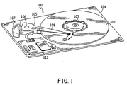
- Eine rotierende Plattendatenspeichereinheit (100), die folgendes umfaßt:eine Plattenantriebsbasis (104);eine rotierbar montierte Platte zum Aufzeichnen von Daten, wobei diese Platte eine Rotationsachse und eine kreisförmige Öffnung in ihrer Mitte zum Montieren dieser Platte auf einer rotierbaren Nabe (103) besitzt;ein einteiliges, aus einem Stück geformtes Nabenelement (103) zum Befestigen der Platte, wobei das Nabenelement zur Rotation um die Achse montiert ist, das Nabenelement Bestandteil eines Spindelmotorrotors (103, 505, 506) ist und das Nabenelement eine Aufnahmestruktur (202) zur Aufnahme dieser Platte umfaßt;eine Gruppe von Rotormagneten (506), die mit dem Nabenelement verbunden sind;einen Spindelmotorständer (508), der mit der Basis für den Antrieb der Rotormagneten verbunden ist;mindestens einen Wandlerkopf (109) zum Lesen der auf dieser Platte gespeicherten Daten; undein bewegliches Stellglied (105), das auf der Plattenantriebsbasis montiert ist und den Wandlerkopf positioniert, um die auf der Platte aufgezeichneten Daten zu lesen;dadurch gekennzeichnet, daß das Nabenelement ebenfalls eine Klammerstruktur (203) zur Arretierung der Platte umfaßt.
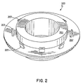
- Die rotierende Plattendatenspeichereinheit gemäß Anspruch 1, wobei das Nabenelement folgendes umfaßt:einen zylindrischen Hohlabschnitt (201) mit einer Achse, die mit der Rotationsachse der Platte zusammenfällt; wobei der zylindrische Hohlabschnitt eine Plattenwelle umgibt und in die kreisförmige öffnung der Platte paßt; undeinen aus dem zylindrischen Hohlabschnitt herausragenden Flanschabschnitt (202), wobei dieser Flanschabschnitt die Aufnahmestruktur zur Aufnahme der Platte darstellt.
- Die rotierende Plattendatenspeichereinheit gemäß Anspruch 1 oder 2, wobei die Klammerstruktur des Nabenelements eine Vielzahl von entlang des Umfangs angeordneten Fingern (203) umfaßt, die aus dem Flanschabschnitt herausragen und die Platte einspannen.
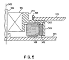
- Die rotierende Plattendatenspeichereinheit gemäß Anspruch 2, wobei der zylindrische Hohlabschnitt (201) des Nabenelements eine Gruppe von Lagern (504) zum Einsetzen des Nabenelements auf der Plattenwelle umgibt.
- Die rotierende Plattendatenspeichereinheit gemäß Anspruch 2, wobei die Gruppe von Rotormagneten (506) mit dem Flanschabschnitt in der Nähe seiner Außenkante verbunden ist und der Ständer (508) in der Umgebung der Plattenwelle und zwischen der Plattenwelle und den Rotormagneten positioniert ist.
- Die rotierende Plattendatenspeichereinheit gemäß einem beliebigen der Ansprüche 1 bis 5, wobei das Nabenelement ein Spritzguß-Polymerteil ist.
- Die rotierende Plattendatenspeichereinheit gemäß einem beliebigen der Ansprüche 1 bis 6, wobei das Nabenelement so geformt ist, daß die Platte auf diesem Nabenelement selbstzentrierend ist.
- Die rotierende Plattendatenspeichereinheit gemäß einem beliebigen der Ansprüche 1 bis 5, wobei das Nabenelement aus einem elastischen Material geformt ist und das elastische Material eine deutlich höhere Elastizität als die Platte aufweist.
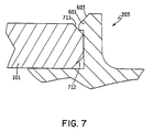
- Die rotierende Plattendatenspeichereinheit gemäß Anspruch 3, wobei:jeder Finger an einem Ende eine Klinke (601) umfaßt und die Finger sich durch diese kreisförmige öffnung dieser Platte hindurch erstrecken und die Klinken die Platte einspannen und eine Längskraft auf die Platte ausüben, wodurch die erste Oberfläche der Platte gegen die Aufnahmefläche gedrückt wird.
- Die rotierende Plattendatenspeichereinheit gemäß Anspruch 9, wobei die öffnung der Platte eine die Rotationsachse umgebende Innenfläche bildet, und wobei die Finger die Innenfläche berühren und jeder Finger dadurch eine Radialkraft auf die Platte ausübt.
- Die rotierende Plattendatenspeichereinheit gemäß Anspruch 10, bei der Klinken entlang einer abgeschrägten, die kreisförmige Öffnung umgebenden Kante (711, 712) die Platte einspannen.
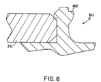
- Die rotierende Plattendatenspeichereinheit gemäß Anspruch 9, bei der jeder Finger eine vorspringende Zunge (802) zum Einspannen in ein Plattenausbauwerkzeug enthält, wobei die vorspringende Zunge aus einer Seite des Fingers herausragt und der Plattenachse gegenüberliegt.
Applications Claiming Priority (3)
| Application Number | Priority Date | Filing Date | Title |
|---|---|---|---|
| US322716 | 1994-10-12 | ||
| US08/322,716 US5486962A (en) | 1994-10-12 | 1994-10-12 | Integral hub and disk clamp for a disk drive storage device |
| PCT/EP1995/003933 WO1996012278A1 (en) | 1994-10-12 | 1995-10-05 | Integral hub and disk clamp for a disk drive storage device |
Publications (2)
| Publication Number | Publication Date |
|---|---|
| EP0786134A1 EP0786134A1 (de) | 1997-07-30 |
| EP0786134B1 true EP0786134B1 (de) | 1998-06-03 |
Family
ID=23256097
Family Applications (1)
| Application Number | Title | Priority Date | Filing Date |
|---|---|---|---|
| EP95935905A Expired - Lifetime EP0786134B1 (de) | 1994-10-12 | 1995-10-05 | Plattenspeichervorrichtung mit integrierter nabe und plattenklammer |
Country Status (17)
| Country | Link |
|---|---|
| US (3) | US5486962A (de) |
| EP (1) | EP0786134B1 (de) |
| JP (1) | JP2870666B2 (de) |
| KR (1) | KR100238921B1 (de) |
| CN (1) | CN1075656C (de) |
| AT (1) | ATE166995T1 (de) |
| BR (1) | BR9504206A (de) |
| CA (1) | CA2197917A1 (de) |
| CZ (1) | CZ287196B6 (de) |
| DE (1) | DE69502835T2 (de) |
| HU (1) | HU215304B (de) |
| MY (1) | MY121941A (de) |
| PL (1) | PL178338B1 (de) |
| RU (1) | RU2139578C1 (de) |
| SG (1) | SG38839A1 (de) |
| TW (1) | TW351805B (de) |
| WO (1) | WO1996012278A1 (de) |
Families Citing this family (38)
| Publication number | Priority date | Publication date | Assignee | Title |
|---|---|---|---|---|
| US5486962A (en) * | 1994-10-12 | 1996-01-23 | International Business Machines Corporation | Integral hub and disk clamp for a disk drive storage device |
| US5596462A (en) * | 1994-11-29 | 1997-01-21 | International Business Machines Corporation | Data storage disk clamp apparatus for minimizing disk clamping force and surface area |
| EP0747897A3 (de) * | 1995-06-06 | 1997-08-06 | Iomega Corp | Nabe-Sperrvorrichtung für Plattenkassette |
| US6084319A (en) * | 1996-10-16 | 2000-07-04 | Canon Kabushiki Kaisha | Linear motor, and stage device and exposure apparatus provided with the same |
| JP3011910B2 (ja) * | 1997-09-19 | 2000-02-21 | 株式会社ケンウッド | ディスク装置のディスククランプ機構 |
| KR100476844B1 (ko) * | 1997-09-25 | 2005-03-17 | 마쯔시다덴기산교 가부시키가이샤 | 디스크 구동장치 |
| US6130801A (en) * | 1997-11-07 | 2000-10-10 | Seagate Technology, Inc. | Composite disc spacer for a disc drive |
| US6212031B1 (en) * | 1997-11-24 | 2001-04-03 | Seagate Technology Llc | Radially-loaded, snap-fit disc mounting system for a disc drive |
| TW420347U (en) * | 1999-01-11 | 2001-01-21 | Sunonwealth Electr Mach Ind Co | Transfer system structure of main axis motor for CD-ROM drive |
| GB2347551B (en) * | 1999-03-01 | 2003-05-07 | Sunonwealth Electr Mach Ind Co | Support structure for a spindle motor of a compact disc machine |
| US6519113B1 (en) * | 1999-04-28 | 2003-02-11 | Seagate Technology Llc | Spindle motor assembly with polymeric motor shaft and hub for rotating a data storage disk |
| US6304412B1 (en) * | 1999-05-12 | 2001-10-16 | Maxtor Corporation | Disk drive with interlocking disk clamp |
| US6579958B2 (en) | 1999-12-07 | 2003-06-17 | The Dow Chemical Company | Superabsorbent polymers having a slow rate of absorption |
| KR20010000390A (ko) * | 2000-09-26 | 2001-01-05 | 이영준 | 김치추출물을 함유하는 노화 및 여드름을 포함한피부개선제 혼합조성물 |
| US6757132B1 (en) | 2000-12-27 | 2004-06-29 | Western Digital Technologies, Inc. | Disk drive comprising a snap-on disk clamp |
| JP2002312999A (ja) * | 2001-04-16 | 2002-10-25 | Mitsumi Electric Co Ltd | ディスク装置 |
| US6798614B2 (en) | 2001-06-01 | 2004-09-28 | Seagate Technology Llc | Releasable disc clamping assembly |
| US6898050B2 (en) * | 2002-02-21 | 2005-05-24 | Seagate Technology Llc | Hydrodynamic bearing motor having a molded plastic hub |
| US6703584B2 (en) | 2002-05-13 | 2004-03-09 | Seagate Technology Llc | Disc clamp adjustment using heat |
| US6771461B2 (en) * | 2002-06-21 | 2004-08-03 | Seagate Technology Llc | Spindle hub having a back iron mountingly coupled to only a hub separating member |
| CN100369362C (zh) * | 2002-11-23 | 2008-02-13 | 深圳易拓科技有限公司 | 磁碟驱动器电机定子的制造方法 |
| US6876517B2 (en) * | 2003-03-10 | 2005-04-05 | Esgw Holdings Limited | Data storage device with spindle motor |
| KR100513315B1 (ko) * | 2003-04-28 | 2005-09-09 | 삼성전기주식회사 | 디스크 드라이브의 홀더 |
| WO2004111602A2 (en) * | 2003-05-16 | 2004-12-23 | University Of Rochester | Colorimetric and fluorescent methods for sensing of oligonucleotides |
| JP2005209312A (ja) * | 2004-01-26 | 2005-08-04 | Matsushita Electric Ind Co Ltd | ディスク保持装置及びディスクチェンジャー装置 |
| KR100555549B1 (ko) * | 2004-01-28 | 2006-03-03 | 삼성전자주식회사 | 하드 디스크 드라이브의 디스크 클램핑 장치 |
| US7823270B2 (en) * | 2004-03-02 | 2010-11-02 | Seagate Technology Llc | Clamp or clamp assembly having a low profile |
| WO2005086152A1 (ja) * | 2004-03-04 | 2005-09-15 | Matsushita Electric Industrial Co., Ltd. | チャッキング装置 |
| WO2005086155A1 (ja) * | 2004-03-04 | 2005-09-15 | Matsushita Electric Industrial Co., Ltd. | チャッキング装置 |
| JP2005251303A (ja) * | 2004-03-04 | 2005-09-15 | Matsushita Electric Ind Co Ltd | チャッキング装置 |
| US20050201010A1 (en) * | 2004-03-12 | 2005-09-15 | Yiren Hong | Disc media retainer |
| KR100604861B1 (ko) * | 2004-05-29 | 2006-07-31 | 삼성전자주식회사 | 디스크 스페이서와 이를 구비한 스핀들 모터 조립체 |
| US7334243B2 (en) * | 2005-08-30 | 2008-02-19 | Delphi Technologies, Inc. | Vane integration into motor hub to enhance CD cooling |
| JP2008217840A (ja) * | 2007-02-28 | 2008-09-18 | Matsushita Electric Ind Co Ltd | スピンドルモータおよびそれを用いた記録再生装置 |
| US8261432B2 (en) * | 2008-07-24 | 2012-09-11 | Hitachi Global Storage Technologies, Netherlands B.V. | Disk spacer drop-proofing tool for disk removal process |
| US8322021B1 (en) | 2008-07-31 | 2012-12-04 | Western Digital Technologies, Inc. | Method of manufacturing a disk drive |
| DE202010008999U1 (de) | 2010-11-10 | 2011-04-28 | Huang, Han-Ching | Vorrichtung zur Spannung zweier Gurte |
| US8493820B1 (en) * | 2012-05-25 | 2013-07-23 | Timothy Edward Langlais | Matched CTE drive |
Family Cites Families (27)
| Publication number | Priority date | Publication date | Assignee | Title |
|---|---|---|---|---|
| US4358843A (en) * | 1980-09-29 | 1982-11-09 | Rager Edgar A | Spindle for centering a data disk |
| JPS5958678A (ja) * | 1982-09-29 | 1984-04-04 | Canon Electronics Inc | 磁気デイスク装置 |
| US4585963A (en) * | 1982-11-01 | 1986-04-29 | Storage Technology Partners Ii | Brushless direct current motor with inverted magnet clip |
| JPS60237672A (ja) * | 1984-05-11 | 1985-11-26 | Hitachi Ltd | デイスク固定機構 |
| NL8503523A (nl) * | 1985-12-20 | 1987-07-16 | Philips Nv | Inrichting voor het centreren van een tijdens bedrijf roterende plaat. |
| JPH0526915Y2 (de) * | 1986-10-29 | 1993-07-08 | ||
| NL8700819A (nl) * | 1987-04-08 | 1988-11-01 | Philips Nv | Inrichting voor het registreren van informatie op of het uitlezen van informatie uit een informatieplaat. |
| JP2699472B2 (ja) * | 1988-10-28 | 1998-01-19 | 日本電気株式会社 | 磁気ディスク装置のスピンドルハブ |
| US5157295A (en) * | 1989-01-25 | 1992-10-20 | Conner Peripherals, Inc. | Under-the-hub disk drive spin motor |
| JPH02252180A (ja) * | 1989-03-27 | 1990-10-09 | Kubota Micro Dain Kk | メモリーディスク装置 |
| US5014143A (en) * | 1989-03-31 | 1991-05-07 | Hitachi Electronics Engineering Co., Ltd. | Data recording disk chuck mechanism |
| US4965476A (en) * | 1989-04-20 | 1990-10-23 | Conner Peripherals, Inc. | Stabilized disk drive spin motor |
| JP2946540B2 (ja) * | 1989-08-16 | 1999-09-06 | ソニー株式会社 | モータ |
| US5048005A (en) * | 1989-10-10 | 1991-09-10 | Ekhoff Donald L | Spindle clamp having a unitary lock member |
| US5193084A (en) * | 1989-11-15 | 1993-03-09 | U.S. Philips Corporation | Device for rotating a disc-shaped information carrier including a turntable and frame |
| JP2861144B2 (ja) * | 1989-11-16 | 1999-02-24 | ソニー株式会社 | ディスクチャッキング機構 |
| JPH0380549U (de) * | 1989-12-04 | 1991-08-19 | ||
| FR2666842B1 (fr) * | 1990-09-17 | 1992-11-20 | Somfy | Dispositif d'enroulement a moteur tubulaire pour stores, volets roulants ou similaires. |
| JP3384002B2 (ja) * | 1992-01-24 | 2003-03-10 | ソニー株式会社 | ディスクテーブル及び記録及び/又は再生装置 |
| WO1993006600A1 (en) * | 1991-09-25 | 1993-04-01 | Integral Peripherals, Inc. | Architecture for low-profile rigid disk drive |
| US5243481A (en) * | 1991-09-25 | 1993-09-07 | Integral Peripherals, Inc. | Clamp for information storage disk |
| JP3351545B2 (ja) * | 1991-10-01 | 2002-11-25 | 日本電産株式会社 | ハードディスク装置 |
| JPH06131783A (ja) * | 1992-10-19 | 1994-05-13 | Asahi Corp:Kk | ディスク保持装置 |
| JP3312942B2 (ja) * | 1993-02-23 | 2002-08-12 | ミネベア株式会社 | 磁気ディスク装置 |
| US5774445A (en) * | 1993-08-09 | 1998-06-30 | Funai Electric Co., Ltd. | Disc clamp mechanism having radial disposed disc pressing elements |
| JPH07105607A (ja) * | 1993-10-07 | 1995-04-21 | Akai Electric Co Ltd | ディスクアダプター |
| US5486962A (en) * | 1994-10-12 | 1996-01-23 | International Business Machines Corporation | Integral hub and disk clamp for a disk drive storage device |
-
1994
- 1994-10-12 US US08/322,716 patent/US5486962A/en not_active Expired - Lifetime
-
1995
- 1995-01-26 TW TW084100714A patent/TW351805B/zh not_active IP Right Cessation
- 1995-04-26 MY MYPI95001096A patent/MY121941A/en unknown
- 1995-04-27 CN CN95105030A patent/CN1075656C/zh not_active Expired - Fee Related
- 1995-04-28 SG SG1995000357A patent/SG38839A1/en unknown
- 1995-09-28 BR BR9504206A patent/BR9504206A/pt not_active Application Discontinuation
- 1995-09-29 KR KR1019950034033A patent/KR100238921B1/ko not_active IP Right Cessation
- 1995-10-05 RU RU97107356A patent/RU2139578C1/ru not_active IP Right Cessation
- 1995-10-05 HU HU9701245A patent/HU215304B/hu not_active IP Right Cessation
- 1995-10-05 EP EP95935905A patent/EP0786134B1/de not_active Expired - Lifetime
- 1995-10-05 JP JP8512902A patent/JP2870666B2/ja not_active Expired - Lifetime
- 1995-10-05 AT AT95935905T patent/ATE166995T1/de not_active IP Right Cessation
- 1995-10-05 DE DE69502835T patent/DE69502835T2/de not_active Expired - Fee Related
- 1995-10-05 PL PL95319484A patent/PL178338B1/pl not_active IP Right Cessation
- 1995-10-05 CA CA002197917A patent/CA2197917A1/en not_active Abandoned
- 1995-10-05 CZ CZ199788A patent/CZ287196B6/cs not_active IP Right Cessation
- 1995-10-05 WO PCT/EP1995/003933 patent/WO1996012278A1/en active IP Right Grant
-
1996
- 1996-08-27 US US08/703,621 patent/US5872681A/en not_active Expired - Lifetime
-
1998
- 1998-06-09 US US09/094,067 patent/US6556376B1/en not_active Expired - Fee Related
Also Published As
| Publication number | Publication date |
|---|---|
| CA2197917A1 (en) | 1996-04-25 |
| BR9504206A (pt) | 1997-04-01 |
| ATE166995T1 (de) | 1998-06-15 |
| CZ287196B6 (en) | 2000-10-11 |
| US5486962A (en) | 1996-01-23 |
| PL178338B1 (pl) | 2000-04-28 |
| PL319484A1 (en) | 1997-08-04 |
| MY121941A (en) | 2006-03-31 |
| JPH10504419A (ja) | 1998-04-28 |
| HUT76704A (en) | 1997-10-28 |
| HU215304B (hu) | 1998-11-30 |
| RU2139578C1 (ru) | 1999-10-10 |
| CN1127401A (zh) | 1996-07-24 |
| KR960015166A (ko) | 1996-05-22 |
| JP2870666B2 (ja) | 1999-03-17 |
| CN1075656C (zh) | 2001-11-28 |
| DE69502835D1 (de) | 1998-07-09 |
| US5872681A (en) | 1999-02-16 |
| SG38839A1 (en) | 1997-04-17 |
| DE69502835T2 (de) | 1999-02-18 |
| WO1996012278A1 (en) | 1996-04-25 |
| KR100238921B1 (ko) | 2000-01-15 |
| CZ8897A3 (en) | 1997-06-11 |
| US6556376B1 (en) | 2003-04-29 |
| EP0786134A1 (de) | 1997-07-30 |
| TW351805B (en) | 1999-02-01 |
Similar Documents
| Publication | Publication Date | Title |
|---|---|---|
| EP0786134B1 (de) | Plattenspeichervorrichtung mit integrierter nabe und plattenklammer | |
| US6222291B1 (en) | Electric motor having axially centered ball bearings | |
| US5590004A (en) | Resilient clamp and compliant element data disk support system | |
| EP0305480B1 (de) | In-wellen-motorbau für plattenantrieb sowie verfahren zu dessen herstellung | |
| US7518823B2 (en) | Spindle motor winding for miniature hard disk drive | |
| US5251082A (en) | Miniaturized disk file pluggable into a card terminal | |
| US6172844B1 (en) | Double grooved spacer for a disc drive | |
| US6603636B2 (en) | Apparatus for centering a disc clamp on a disc pack in a disc drive | |
| US5486961A (en) | Resilient compliant clamp for data storage disk drives | |
| US6567238B1 (en) | Disc clamp for a disc drive | |
| US6417988B1 (en) | Disc clamp for a disc drive | |
| US6282054B1 (en) | Teeth lock ring for a disc stack | |
| KR100433865B1 (ko) | 스핀들 모터 어셈블리 및 디스크 드라이브 내에 정보 저장 디스크를 고정하는 방법 | |
| US6115222A (en) | Single, central limit stop for a disc drive actuator | |
| US5917677A (en) | Disk drive motor spindle hub assembly with separately formed hub ceramic flange attachment | |
| JPH0729295A (ja) | ディスク・ドライブ装置 | |
| GB2345796A (en) | Permanent magnet for an actuator and a method of making the same | |
| US4829657A (en) | In-spindle motor assembly for disk drive and method for fabricating the same | |
| US20030002206A1 (en) | Air razor and disk limiter for a hard disk drive | |
| KR20000028988A (ko) | 하드디스크 드라이브의 보이스 코일 모터용 래치 하우징및 그제작방법 | |
| JPH10222926A (ja) | 光学式ディスク再生装置のディスククランプ機構 |
Legal Events
| Date | Code | Title | Description |
|---|---|---|---|
| PUAI | Public reference made under article 153(3) epc to a published international application that has entered the european phase |
Free format text: ORIGINAL CODE: 0009012 |
|
| 17P | Request for examination filed |
Effective date: 19970410 |
|
| AK | Designated contracting states |
Kind code of ref document: A1 Designated state(s): AT BE CH DE ES FR GB IE IT LI NL SE |
|
| GRAG | Despatch of communication of intention to grant |
Free format text: ORIGINAL CODE: EPIDOS AGRA |
|
| 17Q | First examination report despatched |
Effective date: 19970821 |
|
| GRAG | Despatch of communication of intention to grant |
Free format text: ORIGINAL CODE: EPIDOS AGRA |
|
| GRAH | Despatch of communication of intention to grant a patent |
Free format text: ORIGINAL CODE: EPIDOS IGRA |
|
| GRAH | Despatch of communication of intention to grant a patent |
Free format text: ORIGINAL CODE: EPIDOS IGRA |
|
| GRAA | (expected) grant |
Free format text: ORIGINAL CODE: 0009210 |
|
| AK | Designated contracting states |
Kind code of ref document: B1 Designated state(s): AT BE CH DE ES FR GB IE IT LI NL SE |
|
| PG25 | Lapsed in a contracting state [announced via postgrant information from national office to epo] |
Ref country code: NL Free format text: LAPSE BECAUSE OF FAILURE TO SUBMIT A TRANSLATION OF THE DESCRIPTION OR TO PAY THE FEE WITHIN THE PRESCRIBED TIME-LIMIT Effective date: 19980603 Ref country code: LI Free format text: LAPSE BECAUSE OF FAILURE TO SUBMIT A TRANSLATION OF THE DESCRIPTION OR TO PAY THE FEE WITHIN THE PRESCRIBED TIME-LIMIT Effective date: 19980603 Ref country code: ES Free format text: THE PATENT HAS BEEN ANNULLED BY A DECISION OF A NATIONAL AUTHORITY Effective date: 19980603 Ref country code: CH Free format text: LAPSE BECAUSE OF FAILURE TO SUBMIT A TRANSLATION OF THE DESCRIPTION OR TO PAY THE FEE WITHIN THE PRESCRIBED TIME-LIMIT Effective date: 19980603 Ref country code: BE Free format text: LAPSE BECAUSE OF FAILURE TO SUBMIT A TRANSLATION OF THE DESCRIPTION OR TO PAY THE FEE WITHIN THE PRESCRIBED TIME-LIMIT Effective date: 19980603 Ref country code: AT Free format text: LAPSE BECAUSE OF FAILURE TO SUBMIT A TRANSLATION OF THE DESCRIPTION OR TO PAY THE FEE WITHIN THE PRESCRIBED TIME-LIMIT Effective date: 19980603 |
|
| REF | Corresponds to: |
Ref document number: 166995 Country of ref document: AT Date of ref document: 19980615 Kind code of ref document: T |
|
| REG | Reference to a national code |
Ref country code: CH Ref legal event code: NV Representative=s name: CARL O. BARTH C/O IBM CORPORATION ZURICH INTELLECT Ref country code: CH Ref legal event code: EP |
|
| REF | Corresponds to: |
Ref document number: 69502835 Country of ref document: DE Date of ref document: 19980709 |
|
| ITF | It: translation for a ep patent filed |
Owner name: BRAVI ALFREDO DR. |
|
| REG | Reference to a national code |
Ref country code: IE Ref legal event code: FG4D |
|
| PG25 | Lapsed in a contracting state [announced via postgrant information from national office to epo] |
Ref country code: SE Free format text: LAPSE BECAUSE OF FAILURE TO SUBMIT A TRANSLATION OF THE DESCRIPTION OR TO PAY THE FEE WITHIN THE PRESCRIBED TIME-LIMIT Effective date: 19980903 |
|
| ET | Fr: translation filed | ||
| NLV1 | Nl: lapsed or annulled due to failure to fulfill the requirements of art. 29p and 29m of the patents act | ||
| REG | Reference to a national code |
Ref country code: CH Ref legal event code: PL |
|
| PLBE | No opposition filed within time limit |
Free format text: ORIGINAL CODE: 0009261 |
|
| STAA | Information on the status of an ep patent application or granted ep patent |
Free format text: STATUS: NO OPPOSITION FILED WITHIN TIME LIMIT |
|
| 26N | No opposition filed | ||
| REG | Reference to a national code |
Ref country code: GB Ref legal event code: IF02 |
|
| REG | Reference to a national code |
Ref country code: GB Ref legal event code: 732E |
|
| REG | Reference to a national code |
Ref country code: FR Ref legal event code: TP |
|
| PGFP | Annual fee paid to national office [announced via postgrant information from national office to epo] |
Ref country code: IE Payment date: 20070917 Year of fee payment: 13 |
|
| PGFP | Annual fee paid to national office [announced via postgrant information from national office to epo] |
Ref country code: IT Payment date: 20071030 Year of fee payment: 13 |
|
| PGFP | Annual fee paid to national office [announced via postgrant information from national office to epo] |
Ref country code: GB Payment date: 20071031 Year of fee payment: 13 Ref country code: FR Payment date: 20071026 Year of fee payment: 13 |
|
| PGFP | Annual fee paid to national office [announced via postgrant information from national office to epo] |
Ref country code: DE Payment date: 20071206 Year of fee payment: 13 |
|
| GBPC | Gb: european patent ceased through non-payment of renewal fee |
Effective date: 20081005 |
|
| REG | Reference to a national code |
Ref country code: IE Ref legal event code: MM4A |
|
| REG | Reference to a national code |
Ref country code: FR Ref legal event code: ST Effective date: 20090630 |
|
| PG25 | Lapsed in a contracting state [announced via postgrant information from national office to epo] |
Ref country code: IT Free format text: LAPSE BECAUSE OF NON-PAYMENT OF DUE FEES Effective date: 20081005 Ref country code: DE Free format text: LAPSE BECAUSE OF NON-PAYMENT OF DUE FEES Effective date: 20090501 |
|
| PG25 | Lapsed in a contracting state [announced via postgrant information from national office to epo] |
Ref country code: IE Free format text: LAPSE BECAUSE OF NON-PAYMENT OF DUE FEES Effective date: 20081006 Ref country code: FR Free format text: LAPSE BECAUSE OF NON-PAYMENT OF DUE FEES Effective date: 20081031 |
|
| PG25 | Lapsed in a contracting state [announced via postgrant information from national office to epo] |
Ref country code: GB Free format text: LAPSE BECAUSE OF NON-PAYMENT OF DUE FEES Effective date: 20081005 |