US5590004A - Resilient clamp and compliant element data disk support system - Google Patents
Resilient clamp and compliant element data disk support system Download PDFInfo
- Publication number
- US5590004A US5590004A US08/366,960 US36696094A US5590004A US 5590004 A US5590004 A US 5590004A US 36696094 A US36696094 A US 36696094A US 5590004 A US5590004 A US 5590004A
- Authority
- US
- United States
- Prior art keywords
- disk
- rim
- compliant element
- spindle
- clamping member
- Prior art date
- Legal status (The legal status is an assumption and is not a legal conclusion. Google has not performed a legal analysis and makes no representation as to the accuracy of the status listed.)
- Expired - Fee Related
Links
Images


Classifications
-
- G—PHYSICS
- G11—INFORMATION STORAGE
- G11B—INFORMATION STORAGE BASED ON RELATIVE MOVEMENT BETWEEN RECORD CARRIER AND TRANSDUCER
- G11B17/00—Guiding record carriers not specifically of filamentary or web form, or of supports therefor
- G11B17/02—Details
-
- G—PHYSICS
- G11—INFORMATION STORAGE
- G11B—INFORMATION STORAGE BASED ON RELATIVE MOVEMENT BETWEEN RECORD CARRIER AND TRANSDUCER
- G11B17/00—Guiding record carriers not specifically of filamentary or web form, or of supports therefor
- G11B17/02—Details
- G11B17/038—Centering or locking of a plurality of discs in a single cartridge
Definitions
- the present invention pertains to rotating disk data storage devices and more particularly to a resilient clamp and compliant element for securing one or more data disks on a spindle.
- a common storage device is the rotating magnetic disk drive containing magnetic or optical data storage disks.
- a disk drive typically contains one or more smooth, flat disks which are attached to a common hub or spindle. If more than one disk is employed in a drive, they are stacked on the spindle parallel to each other and spaced apart so that they do not touch one another.
- a clamping mechanism secures the disk or disks to the hub. The disks and hub are rotated in unison at a constant speed by a spindle motor.
- Each disk is formed of a solid disk-shaped base or substrate, having a hole in the middle for the spindle.
- the substrate is commonly aluminum, although glass, ceramic, plastic or other materials are possible.
- the substrate is coated with a thin layer of magnetizable material, and may additionally be coated with a protective layer.
- Data is recorded on the surfaces of magnetic disks in the magnetizable layer.
- minute magnetized patterns representing the data are formed in the magnetizable layer.
- the data patterns are usually arranged in circular concentric tracks. Each track is further divided into a number of sectors. Each sector thus forms an arc, with all the sectors of a track completing a circle.
- a moveable actuator positions a transducer head adjacent the data on the surface to read or write data.
- the actuator may be likened to the tone arm of a phonograph player, and the head to the playing needle.
- Each transducer head is an aerodynamically shaped block of material (usually ceramic) on which is mounted a read/write transducer.
- the block, or slider typically flies above the surface of the disk at an extremely small distance as the disk rotates. In the case of a magnetic disk, the close proximity to the disk surface is critical in enabling the transducer to read from or write to the data patterns in the magnetizable layer.
- Several different transducer designs are used, and in some cases the read transducer is separate from the write transducer.
- the actuator usually pivots about an axis to position the head. It typically includes a solid block near the axis having comb-like arms extending toward the disk, a set of thin suspensions attached to the arms, and an electro-magnetic motor on the opposite side of the axis.
- the transducer heads are attached to the suspensions, one head for each suspension.
- the actuator motor rotates the actuator to position the head over a desired data track. Once the head is positioned over the track, the constant rotation of the disk will eventually bring the desired sector adjacent the head, and the data can then be read or written.
- the clamp that secures one or more data storage disks within an enclosure for rotation in unison with a hub must meet several well recognized design constraints. Among these are the ability to preclude slippage of the disk relative to other portions of the rotating assembly during acceleration and deceleration of the spindle assembly and the capability to resist side shock loads without displacement of a disk with respect to the balance of the assembly. In addition, the clamping force must not distort the disk and the clamp must be capable of assembly and removal without damage to other assembly components including the disks, spindle motor or spindle bearing assemblies and further, the device must not be the source of contaminants within the enclosure in the form of either debris or outgassing of the component materials.
- a typical clamping technique is the use of a series of screws that are equiangularly spaced to secure a circular clamp to compressively retain the disk or disks between the clamp and a flange formed as a part of the hub.
- This technique can result in the localized distortion of the disk adjacent the site of each screw. This phenomena was of little consequence when larger disk sizes and lower areal recording densities were used, but such factors are of concern as disk drive miniaturization occurs.
- drives using 1.8 inch (45.7 mm) diameter disks and subject to the dimensional limitations of the associated form factor the use of a pattern of clamping bolts with the required torque limitations is an unacceptable solution for purposes of mass production manufacturing.
- a solution which is a more acceptable manufacturing technique is the use of a shrink fit clamp which is assembled using the required clamping force and allowed to cool and establish a shrink fit about the hub.
- a shrink fit clamp which is assembled using the required clamping force and allowed to cool and establish a shrink fit about the hub.
- the radial constricting forces tend to affect the running accuracy of the bearing assembly that is mounted at the opposite side of the same hub wall.
- Any clamping technique must be considered with respect to the problems of radial and axial runout that can be influenced by distortion induced by the clamping forces. Radial distortion causes tracks to become noncircular, but the problem can be overcome by writing the tracks subsequent to assembly of the disks to the hub.
- Axial runout is the variation in disk flatness or the departure from a planar surface that tends to vary the flyheight of the transducer head during a cycle of rotation. As the space separating the transducer head from the disk becomes smaller, such as approaching two microinches (50.8 ⁇ 10 -6 mm), the disk flatness becomes a significant concern, and phenomena such as disk clamping that influence such flatness must not impair or compromise this disk parameter.
- a typical objective is to design an inexpensive clamp with an extra low profile to provide both axial and radial clamping forces.
- the present invention comprises a disk assembly which includes a spindle disposed rotatably around a fixed axis.
- the spindle comprises a rim formed at a lower portion of the spindle and a flange spaced axially above the rim.
- At least one disk having a recording surface for recording data is positioned on the spindle.
- the at least one disk has an upper side facing the flange and a lower side facing the rim.
- a resilient clamping member is positioned so that an upper end faces the flange and a lower end faces the upper side of the at least one disk.
- a compliant element is supported by the rim.
- the compliant element is supported by the rim so that the upper portion of the compliant element is compressed toward the upper surface of the rim by the bias of the resilient clamping member under normal operation and so that, during a shock capable of separating the at least one disk from the upper surface of the rim, the compliant element fills at least a portion of the space between the lower side of the at least one disk and the upper surface of the rim.
- the compliant element In the event of a high shock capable of separating a disk from the hub, the compliant element, by expanding to fill the gap or gaps created, reduces the impact of the disk onto the hub. Various benefits are yielded from this solution.
- the assembly helps avoid dinging of the disk during bouncing of the disk onto the hub, thus helping to avoid related disk curvature problems.
- the present invention also reduces the number of bounces of the disk onto the hub and reduces the amount of vibration transmitted to the disk from the bearings in the motor.
- the present invention provides these advantages both during operational and non-operational shock.
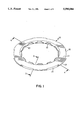
- FIG. 1 is an isometric view of a preferred embodiment of a resilient clamp element of the present invention.
- FIG. 2 is a section view of the clamp of FIG. 1 taken along line 2--2 of FIG. 1.
- FIG. 3 is an isometric section view, partly broken away, of a hub disk assembly mounted on a spindle motor base member which includes a shaft about which the hub-disk assembly rotates.
- FIG. 4 is a section view of the clamp taken along line 4--4 of FIG. 1.
- FIGS. 5 through 8 show the hub, disk and clamp of FIG. 3 and further illustrate a pusher tool and a housing tool, all partly in section and partly broken away, with the figures depicting successive stages of an automated assembly of the preferred clamp of the present invention.
- FIG. 9 shows a magnetic disk drive storage unit according to a preferred embodiment of the present invention.
- FIG. 10 illustrates a preferred embodiment of the present invention in which an O-ring fitted within a groove defined in a rim on the lower portion of the spindle is fully compressed during the insertion of a disk and installation of an upper axial resilient clamp.
- FIG. 10A illustrates an embodiment of the present invention utilizing multiple disks separate by spacers
- FIG. 11A illustrates the insertion of an O-ring into the spindle groove before insertion of the disk.
- FIG. 11B illustrates insertions of a disk and resilient clamp.
- FIG. 11C illustrates separation/bouncing of the disk from the hub due to applied shocks, with the O-ring illustrated taking the slack and reducing the impact force transmitted from the disk to the hub/bearings.
- FIGS. 12A and 12B illustrate an embodiment in which the compliant element is configured as a soft ring molded in an "L" configuration to perform the added task of self-centering the disk.
- FIG. 13 illustrates the use of a set of independent soft balls which can be inserted along the periphery of a spindle underneath the disk to provide the benefits of the present invention.
- FIG. 9 shows a magnetic disk drive storage unit 100 in accordance with a preferred embodiment.
- Disk unit 100 comprises rotatable disk 27, which is attached to hub assembly or spindle 22.
- Hub assembly 22 is rotatably mounted on disk drive base or housing 104.
- Spindle 22 and disk 27 are driven by a drive motor at a constant rotational velocity.
- the drive motor is contained within hub assembly 22.
- Actuator assembly 105 is situated to one side of disk 27. Actuator 105 rotates through an arc about shaft 106 parallel to the axis of the spindle, driven by electro-magnetic motor 107, to position the transducer heads.
- a cover (not shown) mates with base 104 to enclose and protect the disk and actuator assemblies.
- Circuit cards 112 Electronic modules for controlling the operation of the drive and communicating with another device, such as a host computer, are mounted on a circuit card 112 within the head/disk enclosure formed by base 104 and the cover.
- circuit card 112 is mounted within the enclosure and shaped to take up unused space around the disk in order to conserve space, as would be used for a small form factor disk drive.
- card 112 could also be mounted outside the head/disk enclosure, or the base itself could be made as a circuit card for mounting electronic modules directly to it.
- a plurality of head/suspension assemblies 108 are rigidly attached to the prongs of actuator 105.
- An aerodynamic read/write transducer head 109 is located at the end of each head/suspension assembly 108 adjacent the disk surface.
- disk drive 100 is shown with a single disk such as would be used for a small form factor (e.g., PCMCIA Type II form factor), it should be understood that the present invention could utilize a drive having multiple disks mounted on the spindle as shown in FIG. 10A.
- a small form factor e.g., PCMCIA Type II form factor
- FIG. 1 is an isometric view of the preferred embodiment of a resilient clamp 10 of the present invention.
- Clamp 10 includes an annulus 11 from which a series of ears or lobes 12 extend from an inner diameter, generally frusto-conical surface 13.
- an interrupted flange is formed with a series of six flange type projections 15 separated by a like series of interrupted angular portions 16.
- FIGS. 2 and 4 also show the lobes 12 which extend inward and upward from the surface 13 and the flange segments 15. The lobe 12 upward and inward projection and the reduced thickness permit axial assembly of the clamp 10 wherein the lobes 12 yield radially inward as the clamp is forced over the end of the hub 22.
- the ears or lobes 12 spring behind the hub flange 23, as seen in FIG. 3 showing the assembled condition. Additionally, an annular projection 18 extends axially downward from the annulus lower surface 19.
- the upper and lower axial end surfaces 45 and 19 of the clamp annulus 11 are slightly frusto-conical, diverging from a radial plane by an angle A of 12 degrees as shown.
- the angle A may vary widely depending upon the component material parameters, the clamping force used, and the geometry of both the clamp and the cooperating spindle hub.
- the amount of glass filler added to the resilient plastic material would be significantly increased to achieve a clamp coefficient of thermal expansion that is identical to that of the glass disk.
- Such a clamp would have a reduced resiliency and, accordingly, the magnitude of angle A would be reduced.
- Clamp 10 requires the use of a compliant material such as polymer based materials.
- Ultem 6000/2400 was selected due its superior thermal stability (Ultem is a trademark of GE Company).
- Polymer-based materials are readily available which have good thermal behavior, limited susceptibility to humidity and low outgassing tendencies.
- Such materials can further be filled with glass and carbon in order to match the coefficient of linear expansion of the aluminum disk.
- FIG. 3 shows the assembled clamp 10 compressively retaining disk 27 to hub 22.
- the annular projection 18 compresses and deforms against the upper surface of disk 27 to compressively bias the disk toward and preferably against the raised annular surface 29 of hub rim 30.
- a compressive force is also applied by displacement of the clamp from the frusto-conical configuration of the unassembled clamp to the substantially radial surface of the axial ends in the assembled condition.
- the combination of the present invention comprises a compliant element 52 supported by rim 30 of spindle or hub 22.
- Compliant element 52 is supported by rim 30 so that the upper portion of the compliant element is compressed toward the upper surface 29 of rim 30 by the bias of resilient clamping member 10 under normal operation and so that, during a shock capable of separating disk 27 from upper surface 29 of the rim, the compliant element fills at least a portion of the space between the lower side of disk 27 and the upper surface of the rim.
- the spindle or hub defines a recess 50 formed into upper surface 29 of rim 30.
- the compliant element is placed into recess or groove 50 so that, in its relaxed state, a portion of the compliant element protrudes above upper surface 29 of rim 30.
- Compliant element 52 requires the use of a compliant material such as polymer based materials.
- Ultem 6000/2400 was selected due its superior thermal stability (Ultem is a trademark of GE Company).
- Polymer-based materials are readily available which have good thermal behavior, limited susceptibility to humidity and low outgassing tendencies. Such materials can further be filled with glass and carbon in order to match the coefficient of linear expansion of the aluminum disk.
- the material selected for compliant element 52 should comprise a material which will compress toward and preferably completely to upper surface 29 of rim 30 when under normal assembly or operating conditions and, during a shock capable of separating disk 27 away from upper surface 29 of rim 30, will fill at least a portion of space 54 (see FIG. 11B) between the lower side of disk 27 and upper surface 29 of rim 30.
- the compliant element may comprise a variety of shapes.
- the cross-sectional illustrations of FIGS. 11A, 11B, and 11C show the compliant element as an O-ring or ball 52.
- recess or groove 50 is shown in rectangular cross section in these figures, a recess or groove 50 could be formed with varying cross sections, including cross sections with a rounded or oval configuration.
- the compliant element 52 is an O-ring, recess 50 would typically be an annular groove.
- the compliant element 52 comprises a series of elements, for example, a series of balls, recess 50 typically comprises a series of cups 64 (see FIG. 13) or the like to hold the individual compliant elements 52.
- FIG. 11A illustrates the insertion of an O-ring or ball 52 into recess 50 in rim 30 of spindle 22.
- FIG. 11b illustrates insertion of disk 27 and resilient clamp 10.
- resilient clamp 10 provides a bias which compresses compliant element 52 so that the upper portion of the element, for example, the upper portion of an O-ring or ball 52, is compressed toward the level of upper surface 29 of rim 30 under normal operation.
- the compliant element such as O-ring or ball 52 fills at least a portion of space 54 above the element between the lower side of disk 27 and the upper surface 29 of rim 30. As is shown in FIG.
- resilient clamping member 10 fully compress the compliant element during insertion of disk 27 onto spindle 22 so that the compliant element is compressed completely to the level of upper surface 29 of the rim under normal non-shock operational or non-operational conditions.
- the compliant element fills at least a portion of space 54 (see FIG. 11B) between the lower side of disk 27 and upper surface 29 of the rim.
- the compliant element may comprise a soft ring formed in substantially an "L" configuration comprising a vertical leg member 58 and a horizontal leg member 60.
- vertical leg member 58 preferably provides an outer surface for self-centering disk 27, and horizontal leg member 60 is arranged and configured so that an upper portion of horizontal leg member 60 is compressed toward the level of (and preferably to the level of) upper surface 29 of the rim by resilient clamping member 10 under normal operation and so that, during a high shock capable of separating disk 27 from upper surface 29 of the rim, the horizontal leg member fills at least a portion of the space between the lower side of disk 27 and upper surface 29 of the rim.
- the present disk assembly may comprise a plurality of compliant elements supported by the rim wherein each of the compliant elements are supported by the rim and are compressed toward the level of (and preferably to the level of) upper surface 29 of the rim by resilient clamping member 10 under normal operation and so that, during a shock capable of separating disk 27 from upper surface 29 of the rim, each of the compliant elements fill at least a portion of the space above the elements between the lower side of disk 27 and upper surface 29 of the rim.
- the plurality of compliant elements may each comprise a ball, which may be held in place on the rim of spindle or hub 22 by cups 64. Cups 64 may have a square, round, oval or other cross-sectional configuration.
- FIG. 3 also illustrates the organization of a typical hub and spindle motor.
- the spindle motor includes a base member 33 from which projects a dead shaft 35 about which the hub-disk assembly rotates, being supported on the shaft 35 by a pair of ball bearing assemblies 36.
- the spindle motor includes core and winding elements 37 supported on the base surface and an annular permanent magnet secured to hub 22.
- Hub 22 is formed of steel which provides electromagnetic isolation of the spindle motor from the other magnetic systems of the data storage drive mechanism and eliminates the need for an additional magnetically permeable element to provide a flux path for the motor.
- FIGS. 5 through 8 show a preferred sequence of securing resilient clamp 10 to hub 22 to compressively capture disk 27 between the clamp and upper surface 29 of hub rim 30.
- a pusher tool 40 and a housing tool 41 are shown with each of the assembly elements, with the tools partly in section and partly broken away, to schematically illustrate the assembly procedure.
- the clamp normally has a somewhat conical configuration, as shown in FIG. 5, until compressed and flattened into the assembled condition.
- the housing tool 41 has six downwardly extending projections 42 that present grooves 43 in which the clamp flange portions 15 are received to retain and align the unassembled clamp.
- pusher tool 40 is in a relaxed or upwardly retracted position, and compliant element 52 is shown in a relaxed state, with the upper surface of compliant element 52 shown protruding above upper surface 29 of rim 30.
- FIG. 7 shows clamp 10 assembled to hub 22 as the pusher tool 40 and housing tool 41 are both moved axially downward causing clamp lobes 12 to deflect radially inward, pass over the end of hub 22 and snap into the secured, assembled position behind hub flange 23.
- Clamp 10 is now on hub 22 with the pusher tool 40 still holding it in the flattened configuration.
- compliant element 52 is shown in FIG. 7 in a compressed state, with the upper portion of compliant element 52 being compressed to its preferred position maintained during normal assembly and operating conditions, the upper surface of compliant element 52 being shown compressed completely to the level of upper surface 29 of rim 30 by resilient clamping member 10.
- FIG. 8 shows compliant element 52 in a compressed state, with the upper portion of compliant element 52 being compressed to its preferred position maintained during normal assembly and operating conditions, the upper surface of compliant element 52 being shown compressed completely to the level of upper surface 29 of rim 30 by resilient clamping member 10.
- compliant element 52 is supported by rim 30 so that an upper portion of the compliant element is compressed toward, and preferably to, the level of upper surface 29 of rim 30 by the bias of resilient clamping member 10 under normal conditions and, during a shock capable of separating disk 27 away from upper surface 29 of rim 30, compliant element 52 fills at least a portion of space 54 (see FIG. 11B) between the lower side of disk 27 and upper surface 29 of rim 30.
- the total indicated runout (TIR) that measures the axial variation of the disk surface flatness during rotation, shows no significant difference between clamped and unclamped disks.
- TIR total indicated runout
- the TIR was substantially unchanged when disks were clamped and, with thicker aluminum disks of 25 mils (63.5 mm), the TIR of the clamped disks was actually lower than that of the unclamped disks.
- the compliant element In the event of a high shock capable of separating the disk from the hub, the compliant element, by expanding to fill the gap or gaps created, reduces the impact of the disk onto the hub. This reduced impact provides a reduction in shocks transmitted to the hub during disk bouncing.
- the assembly also helps avoid dinging of the disk during bouncing of the disk onto the hub, thus helping to avoid related disk curvature problems.
- the present invention also reduces the number of bounces of the disk onto the hub and reduces the amount of vibration transmitted to the disk from the bearings in the motor. The present invention provides these advantages both during operational and non-operational shock.
Landscapes
- Holding Or Fastening Of Disk On Rotational Shaft (AREA)
Abstract
Description
Claims (18)
Priority Applications (1)
| Application Number | Priority Date | Filing Date | Title |
|---|---|---|---|
| US08/366,960 US5590004A (en) | 1994-12-30 | 1994-12-30 | Resilient clamp and compliant element data disk support system |
Applications Claiming Priority (1)
| Application Number | Priority Date | Filing Date | Title |
|---|---|---|---|
| US08/366,960 US5590004A (en) | 1994-12-30 | 1994-12-30 | Resilient clamp and compliant element data disk support system |
Publications (1)
| Publication Number | Publication Date |
|---|---|
| US5590004A true US5590004A (en) | 1996-12-31 |
Family
ID=23445357
Family Applications (1)
| Application Number | Title | Priority Date | Filing Date |
|---|---|---|---|
| US08/366,960 Expired - Fee Related US5590004A (en) | 1994-12-30 | 1994-12-30 | Resilient clamp and compliant element data disk support system |
Country Status (1)
| Country | Link |
|---|---|
| US (1) | US5590004A (en) |
Cited By (29)
| Publication number | Priority date | Publication date | Assignee | Title |
|---|---|---|---|---|
| US5862011A (en) * | 1995-08-24 | 1999-01-19 | Hitachi, Ltd. | PC card type magnetic disk device |
| US5877571A (en) * | 1997-10-30 | 1999-03-02 | Western Digital Corporation | Head disk assembly having a washer between a disk clamp and disk and method of making |
| US5880906A (en) * | 1997-09-17 | 1999-03-09 | Seagate Technology, Inc. | Disc clamp with contoured peripheral wall Height |
| US5923498A (en) * | 1995-12-18 | 1999-07-13 | Seagate Technology, Inc. | Disc clamp assembly for a disc drive |
| US6040957A (en) * | 1997-06-03 | 2000-03-21 | Quantum Corporation | Disk drive disk damper |
| US6064547A (en) * | 1998-09-15 | 2000-05-16 | Quantum Corporation | Damped disk separator |
| US6177173B1 (en) | 1998-07-01 | 2001-01-23 | 3M Innovative Properties Company | Damped laminates having welded through holes and/or edges with decreased spring back and improved fastener force retention and, a method of making |
| US6252843B1 (en) * | 1999-04-09 | 2001-06-26 | Hewlett Packard Company | Automatic clamping of compact discs |
| US6285525B1 (en) | 1998-07-01 | 2001-09-04 | 3M Innovative Properties Company | Damped spacer articles and disk drive assemblies containing damped spacer articles |
| US20020069509A1 (en) * | 2000-12-13 | 2002-06-13 | Seagate Technology Llc | Method for forming a disc stack assembly |
| US6483661B1 (en) | 1999-04-21 | 2002-11-19 | Stephen Robert Martin | Disc drive disc clamp for exerting an equalized clamping force on a disc |
| US6542330B1 (en) | 1999-06-30 | 2003-04-01 | Seagate Technology Llc | Disc clamp for improved disc stack balance |
| US6567238B1 (en) | 1999-10-12 | 2003-05-20 | Seagate Technology Llc | Disc clamp for a disc drive |
| US6606221B2 (en) | 2000-11-15 | 2003-08-12 | Seagate Technology Llc | Viscoelastic disc clamp using adhesive with radial compliance |
| US20030218830A1 (en) * | 2002-05-23 | 2003-11-27 | International Business Machines Corporation | Deformable ring clamping device for warp-free disk stack assembly in a data storage disk drive |
| US6658714B2 (en) | 2000-10-10 | 2003-12-09 | Seagate Technology Llc | Compliant clamping mechanism for accurate alignment of a group of miniature parts |
| US6703584B2 (en) | 2002-05-13 | 2004-03-09 | Seagate Technology Llc | Disc clamp adjustment using heat |
| US6757132B1 (en) * | 2000-12-27 | 2004-06-29 | Western Digital Technologies, Inc. | Disk drive comprising a snap-on disk clamp |
| US6760188B2 (en) | 2000-12-13 | 2004-07-06 | Seagate Technology Llc | Disc stack assembly having a clamp plate and a retaining ring to clamp a disc to a spindle motor hub |
| US6850389B2 (en) | 2002-08-15 | 2005-02-01 | Seagate Technology Llc | Crowned disc clamp |
| US20050036235A1 (en) * | 2003-08-11 | 2005-02-17 | Ng Hwaliang | Pop-on disc clamp for a data storage device |
| US6888698B1 (en) | 2001-08-31 | 2005-05-03 | Western Digital Technologies, Inc. | Disk drive including spindle motor hub and damping members for damping disk movement |
| US20050162776A1 (en) * | 2004-01-28 | 2005-07-28 | Samsung Electronics Co. Ltd. | Disk clamping apparatus and method for hard disk drive and hard disk drive with the same |
| US20050195524A1 (en) * | 2004-03-02 | 2005-09-08 | Choo Victor C. | Clamp or clamp assembly having a low profile |
| US20050264928A1 (en) * | 2004-05-29 | 2005-12-01 | Samsung Electronics Co., Ltd. | Disk spacer and spindle motor assembly employing the same |
| US20060126220A1 (en) * | 2004-12-10 | 2006-06-15 | Matsushita Electric Industrial Co., Ltd. | Disk drive device |
| US20070035876A1 (en) * | 2005-08-10 | 2007-02-15 | Martin Engesser | Disc clamp for a disc drive |
| US20080310049A1 (en) * | 2007-06-12 | 2008-12-18 | Jr-Yi Shen | Fluid dyamic bearing with novel air-gap |
| US8322021B1 (en) | 2008-07-31 | 2012-12-04 | Western Digital Technologies, Inc. | Method of manufacturing a disk drive |
Citations (25)
| Publication number | Priority date | Publication date | Assignee | Title |
|---|---|---|---|---|
| US3587074A (en) * | 1969-09-29 | 1971-06-22 | Singer General Precision | Magnetic disc assembly with annular flange |
| US3608686A (en) * | 1969-12-18 | 1971-09-28 | Thomas B Martin Sr | Automatic release clutch |
| US4022478A (en) * | 1975-07-03 | 1977-05-10 | Zenith Radio Corporation | Push-button video disc hub |
| JPS60193156A (en) * | 1984-03-14 | 1985-10-01 | Fujitsu Ltd | Fitting structure of magnetic disk |
| GB2158633A (en) * | 1984-05-11 | 1985-11-13 | Hewlett Packard Co | Disc mounting apparatus for use in disc memory devices |
| US4577756A (en) * | 1984-04-26 | 1986-03-25 | Hennessy Michael P | Protective canister for computer discs |
| JPS6442052A (en) * | 1987-08-07 | 1989-02-14 | Nec Corp | Spindle motor |
| US4835637A (en) * | 1987-09-08 | 1989-05-30 | International Business Machines Corporation | Disk file with in-hub motor |
| US4864443A (en) * | 1987-11-02 | 1989-09-05 | Seagate Technology, Inc. | Disc clamping device |
| US4933927A (en) * | 1989-02-24 | 1990-06-12 | Conner Peripherals, Inc. | Disk centering method and apparatus for centering disks for disk drives |
| JPH02166682A (en) * | 1988-12-20 | 1990-06-27 | Tokico Ltd | magnetic disk device |
| US4945432A (en) * | 1988-03-31 | 1990-07-31 | Hoya Electronics Corporation | Magnetic disk drive with brittle disks |
| US5006942A (en) * | 1989-04-17 | 1991-04-09 | International Business Machines Corporation | Rigid magnetic data storage disk assembly with grooved spacer |
| JPH03134854A (en) * | 1989-10-20 | 1991-06-07 | Tokico Ltd | Method and structure for clamping magnetic disk in magnetic disk device |
| US5025340A (en) * | 1989-10-16 | 1991-06-18 | Roger Peters | Rotary chuck for centering and retaining data discs |
| US5075808A (en) * | 1989-10-30 | 1991-12-24 | Kabushiki Kaisha Toshiba | Retaining clamp for a disc storage apparatus |
| US5101306A (en) * | 1989-10-30 | 1992-03-31 | Kabushiki Kaisha Toshiba | Releasable controlled force clamp for disk storage apparatus |
| JPH04195958A (en) * | 1990-11-28 | 1992-07-15 | Toshiba Corp | Magnetic disk device |
| JPH04255957A (en) * | 1991-02-08 | 1992-09-10 | Seiko Epson Corp | disk device |
| US5243481A (en) * | 1991-09-25 | 1993-09-07 | Integral Peripherals, Inc. | Clamp for information storage disk |
| US5267106A (en) * | 1992-06-04 | 1993-11-30 | International Business Machines Corporation | System for clamping a plurality of disks to a hub |
| US5270999A (en) * | 1990-12-10 | 1993-12-14 | Conner Peripherals, Inc. | Apparatus and method for reducing disk distortion |
| US5272581A (en) * | 1990-09-14 | 1993-12-21 | Hitachi, Ltd. | Disk-type recording medium and storage apparatus |
| US5274517A (en) * | 1988-07-18 | 1993-12-28 | Seagate Technology, Inc. | Disk clamp with annular spring section |
| US5317225A (en) * | 1990-12-29 | 1994-05-31 | Nippon Densan Corporation | Spindle motor and disk clamp mechanism used therein |
-
1994
- 1994-12-30 US US08/366,960 patent/US5590004A/en not_active Expired - Fee Related
Patent Citations (25)
| Publication number | Priority date | Publication date | Assignee | Title |
|---|---|---|---|---|
| US3587074A (en) * | 1969-09-29 | 1971-06-22 | Singer General Precision | Magnetic disc assembly with annular flange |
| US3608686A (en) * | 1969-12-18 | 1971-09-28 | Thomas B Martin Sr | Automatic release clutch |
| US4022478A (en) * | 1975-07-03 | 1977-05-10 | Zenith Radio Corporation | Push-button video disc hub |
| JPS60193156A (en) * | 1984-03-14 | 1985-10-01 | Fujitsu Ltd | Fitting structure of magnetic disk |
| US4577756A (en) * | 1984-04-26 | 1986-03-25 | Hennessy Michael P | Protective canister for computer discs |
| GB2158633A (en) * | 1984-05-11 | 1985-11-13 | Hewlett Packard Co | Disc mounting apparatus for use in disc memory devices |
| JPS6442052A (en) * | 1987-08-07 | 1989-02-14 | Nec Corp | Spindle motor |
| US4835637A (en) * | 1987-09-08 | 1989-05-30 | International Business Machines Corporation | Disk file with in-hub motor |
| US4864443A (en) * | 1987-11-02 | 1989-09-05 | Seagate Technology, Inc. | Disc clamping device |
| US4945432A (en) * | 1988-03-31 | 1990-07-31 | Hoya Electronics Corporation | Magnetic disk drive with brittle disks |
| US5274517A (en) * | 1988-07-18 | 1993-12-28 | Seagate Technology, Inc. | Disk clamp with annular spring section |
| JPH02166682A (en) * | 1988-12-20 | 1990-06-27 | Tokico Ltd | magnetic disk device |
| US4933927A (en) * | 1989-02-24 | 1990-06-12 | Conner Peripherals, Inc. | Disk centering method and apparatus for centering disks for disk drives |
| US5006942A (en) * | 1989-04-17 | 1991-04-09 | International Business Machines Corporation | Rigid magnetic data storage disk assembly with grooved spacer |
| US5025340A (en) * | 1989-10-16 | 1991-06-18 | Roger Peters | Rotary chuck for centering and retaining data discs |
| JPH03134854A (en) * | 1989-10-20 | 1991-06-07 | Tokico Ltd | Method and structure for clamping magnetic disk in magnetic disk device |
| US5075808A (en) * | 1989-10-30 | 1991-12-24 | Kabushiki Kaisha Toshiba | Retaining clamp for a disc storage apparatus |
| US5101306A (en) * | 1989-10-30 | 1992-03-31 | Kabushiki Kaisha Toshiba | Releasable controlled force clamp for disk storage apparatus |
| US5272581A (en) * | 1990-09-14 | 1993-12-21 | Hitachi, Ltd. | Disk-type recording medium and storage apparatus |
| JPH04195958A (en) * | 1990-11-28 | 1992-07-15 | Toshiba Corp | Magnetic disk device |
| US5270999A (en) * | 1990-12-10 | 1993-12-14 | Conner Peripherals, Inc. | Apparatus and method for reducing disk distortion |
| US5317225A (en) * | 1990-12-29 | 1994-05-31 | Nippon Densan Corporation | Spindle motor and disk clamp mechanism used therein |
| JPH04255957A (en) * | 1991-02-08 | 1992-09-10 | Seiko Epson Corp | disk device |
| US5243481A (en) * | 1991-09-25 | 1993-09-07 | Integral Peripherals, Inc. | Clamp for information storage disk |
| US5267106A (en) * | 1992-06-04 | 1993-11-30 | International Business Machines Corporation | System for clamping a plurality of disks to a hub |
Cited By (39)
| Publication number | Priority date | Publication date | Assignee | Title |
|---|---|---|---|---|
| US5862011A (en) * | 1995-08-24 | 1999-01-19 | Hitachi, Ltd. | PC card type magnetic disk device |
| US5923498A (en) * | 1995-12-18 | 1999-07-13 | Seagate Technology, Inc. | Disc clamp assembly for a disc drive |
| US6040957A (en) * | 1997-06-03 | 2000-03-21 | Quantum Corporation | Disk drive disk damper |
| US5880906A (en) * | 1997-09-17 | 1999-03-09 | Seagate Technology, Inc. | Disc clamp with contoured peripheral wall Height |
| US5877571A (en) * | 1997-10-30 | 1999-03-02 | Western Digital Corporation | Head disk assembly having a washer between a disk clamp and disk and method of making |
| US6285525B1 (en) | 1998-07-01 | 2001-09-04 | 3M Innovative Properties Company | Damped spacer articles and disk drive assemblies containing damped spacer articles |
| US6177173B1 (en) | 1998-07-01 | 2001-01-23 | 3M Innovative Properties Company | Damped laminates having welded through holes and/or edges with decreased spring back and improved fastener force retention and, a method of making |
| US6456455B2 (en) | 1998-07-01 | 2002-09-24 | 3M Innovative Properties Company | Damped spacer articles and disk drive assemblies containing damped spacer articles |
| US6064547A (en) * | 1998-09-15 | 2000-05-16 | Quantum Corporation | Damped disk separator |
| US6252843B1 (en) * | 1999-04-09 | 2001-06-26 | Hewlett Packard Company | Automatic clamping of compact discs |
| US6483661B1 (en) | 1999-04-21 | 2002-11-19 | Stephen Robert Martin | Disc drive disc clamp for exerting an equalized clamping force on a disc |
| US6542330B1 (en) | 1999-06-30 | 2003-04-01 | Seagate Technology Llc | Disc clamp for improved disc stack balance |
| US6567238B1 (en) | 1999-10-12 | 2003-05-20 | Seagate Technology Llc | Disc clamp for a disc drive |
| US6658714B2 (en) | 2000-10-10 | 2003-12-09 | Seagate Technology Llc | Compliant clamping mechanism for accurate alignment of a group of miniature parts |
| US6606221B2 (en) | 2000-11-15 | 2003-08-12 | Seagate Technology Llc | Viscoelastic disc clamp using adhesive with radial compliance |
| US20020069509A1 (en) * | 2000-12-13 | 2002-06-13 | Seagate Technology Llc | Method for forming a disc stack assembly |
| US6807721B2 (en) | 2000-12-13 | 2004-10-26 | Seagate Technology Llc | Method for forming a disc stack assembly |
| US6760188B2 (en) | 2000-12-13 | 2004-07-06 | Seagate Technology Llc | Disc stack assembly having a clamp plate and a retaining ring to clamp a disc to a spindle motor hub |
| US6757132B1 (en) * | 2000-12-27 | 2004-06-29 | Western Digital Technologies, Inc. | Disk drive comprising a snap-on disk clamp |
| US6888698B1 (en) | 2001-08-31 | 2005-05-03 | Western Digital Technologies, Inc. | Disk drive including spindle motor hub and damping members for damping disk movement |
| US6703584B2 (en) | 2002-05-13 | 2004-03-09 | Seagate Technology Llc | Disc clamp adjustment using heat |
| US20030218830A1 (en) * | 2002-05-23 | 2003-11-27 | International Business Machines Corporation | Deformable ring clamping device for warp-free disk stack assembly in a data storage disk drive |
| US6850389B2 (en) | 2002-08-15 | 2005-02-01 | Seagate Technology Llc | Crowned disc clamp |
| US7215509B2 (en) | 2003-08-11 | 2007-05-08 | Seagate Technology Llc | Pop-on disc clamp for a data storage device |
| US20050036235A1 (en) * | 2003-08-11 | 2005-02-17 | Ng Hwaliang | Pop-on disc clamp for a data storage device |
| SG140449A1 (en) * | 2003-08-11 | 2008-03-28 | Seagate Technology Llc | Pop-on disc clamp for a data storage device |
| US20050162776A1 (en) * | 2004-01-28 | 2005-07-28 | Samsung Electronics Co. Ltd. | Disk clamping apparatus and method for hard disk drive and hard disk drive with the same |
| EP1560212A3 (en) * | 2004-01-28 | 2007-10-31 | Samsung Electronics Co., Ltd. | Disk clamping apparatus and hard disk drive with the same |
| US7589935B2 (en) * | 2004-01-28 | 2009-09-15 | Samsung Electronics Co., Ltd. | Disk clamping apparatus for hard disk drive and hard disk drive with the same |
| US20050195524A1 (en) * | 2004-03-02 | 2005-09-08 | Choo Victor C. | Clamp or clamp assembly having a low profile |
| US7823270B2 (en) | 2004-03-02 | 2010-11-02 | Seagate Technology Llc | Clamp or clamp assembly having a low profile |
| US20050264928A1 (en) * | 2004-05-29 | 2005-12-01 | Samsung Electronics Co., Ltd. | Disk spacer and spindle motor assembly employing the same |
| US7538975B2 (en) | 2004-05-29 | 2009-05-26 | Samsung Electronics Co., Ltd. | Disk spacer and spindle motor assembly employing the same |
| US20060126220A1 (en) * | 2004-12-10 | 2006-06-15 | Matsushita Electric Industrial Co., Ltd. | Disk drive device |
| US20070035876A1 (en) * | 2005-08-10 | 2007-02-15 | Martin Engesser | Disc clamp for a disc drive |
| US7379267B2 (en) * | 2005-08-10 | 2008-05-27 | Minebea Co., Ltd. | Disc clamp with snap fit for a disc drive |
| US20080310049A1 (en) * | 2007-06-12 | 2008-12-18 | Jr-Yi Shen | Fluid dyamic bearing with novel air-gap |
| US8322021B1 (en) | 2008-07-31 | 2012-12-04 | Western Digital Technologies, Inc. | Method of manufacturing a disk drive |
| US9196295B1 (en) | 2008-07-31 | 2015-11-24 | Western Digital Technologies, Inc. | Disk to motor hub swage attachment |
Similar Documents
| Publication | Publication Date | Title |
|---|---|---|
| US5590004A (en) | Resilient clamp and compliant element data disk support system | |
| US5486961A (en) | Resilient compliant clamp for data storage disk drives | |
| US5872681A (en) | Integral hub and disk clamp for a disk drive storage device | |
| US8755148B1 (en) | Disk drive with balance plug having longitudinal retainers | |
| US5377060A (en) | Ultra slim data storage module utilizing plural flexible disks | |
| US6411472B1 (en) | Dual metal laminate tolerance ring for acoustic and vibration damping | |
| US8446688B1 (en) | Drive with circumferential disk limiter | |
| US6473270B1 (en) | Actuator shock snubber | |
| US6603636B2 (en) | Apparatus for centering a disc clamp on a disc pack in a disc drive | |
| EP0522717A2 (en) | Pivot mechanism for a rotary actuator | |
| KR100421054B1 (en) | Hard disk drive having a means for reducing disk fluttering | |
| US6212029B1 (en) | Snubber for a disc drive | |
| US6282054B1 (en) | Teeth lock ring for a disc stack | |
| KR100433865B1 (en) | Spindle motor assembly and a method of securing an information storage disc within disc drive | |
| US7126787B2 (en) | System and method for hard disk drive with disk clamp annular rim inner wall engaging hub annular recess outer wall | |
| US6680823B2 (en) | Moveable outer stop | |
| US6543124B2 (en) | Voice coil motor attachment for a hard disc assembly | |
| US20120162824A1 (en) | Retaining a spoiler in a hard disk drive | |
| KR100433708B1 (en) | Disc stack assembly for disc drive | |
| US7283325B2 (en) | Apparatus and system for centering media disks on the hub of a spindle motor in a hard disk drive | |
| US7155807B2 (en) | Method of centering media disks on the hub of a spindle motor in a hard disk drive | |
| JPH06251531A (en) | Magnetic disk unit | |
| KR19980015950A (en) | A compact hard disk drive device that prevents disk slip | |
| HK1163921B (en) | Disk drive with balance plug having longitudinal retainers |
Legal Events
| Date | Code | Title | Description |
|---|---|---|---|
| AS | Assignment |
Owner name: INTERNATIONAL BUSINESS MACHINES CORPORATION Free format text: ASSIGNMENT OF ASSIGNORS INTEREST;ASSIGNOR:BOUTAGHOU, ZINE-EDDINE;REEL/FRAME:007404/0841 Effective date: 19950128 |
|
| FPAY | Fee payment |
Year of fee payment: 4 |
|
| AS | Assignment |
Owner name: MARIANA HDD B.V., NETHERLANDS Free format text: ASSIGNMENT OF ASSIGNORS INTEREST;ASSIGNOR:INTERNATIONAL BUSINESS MACHINES CORPORATION;REEL/FRAME:013663/0348 Effective date: 20021231 |
|
| AS | Assignment |
Owner name: HITACHI GLOBAL STORAGE TECHNOLOGIES NETHERLANDS B. Free format text: CHANGE OF NAME;ASSIGNOR:MARIANA HDD B.V.;REEL/FRAME:013746/0146 Effective date: 20021231 |
|
| FPAY | Fee payment |
Year of fee payment: 8 |
|
| REMI | Maintenance fee reminder mailed | ||
| LAPS | Lapse for failure to pay maintenance fees | ||
| STCH | Information on status: patent discontinuation |
Free format text: PATENT EXPIRED DUE TO NONPAYMENT OF MAINTENANCE FEES UNDER 37 CFR 1.362 |
|
| FP | Lapsed due to failure to pay maintenance fee |
Effective date: 20081231 |