EP0786134B1 - Disk storage device with integral hub and disk clamp - Google Patents
Disk storage device with integral hub and disk clamp Download PDFInfo
- Publication number
- EP0786134B1 EP0786134B1 EP95935905A EP95935905A EP0786134B1 EP 0786134 B1 EP0786134 B1 EP 0786134B1 EP 95935905 A EP95935905 A EP 95935905A EP 95935905 A EP95935905 A EP 95935905A EP 0786134 B1 EP0786134 B1 EP 0786134B1
- Authority
- EP
- European Patent Office
- Prior art keywords
- disk
- hub
- storage device
- data storage
- hub member
- Prior art date
- Legal status (The legal status is an assumption and is not a legal conclusion. Google has not performed a legal analysis and makes no representation as to the accuracy of the status listed.)
- Expired - Lifetime
Links
Images


Classifications
-
- G—PHYSICS
- G11—INFORMATION STORAGE
- G11B—INFORMATION STORAGE BASED ON RELATIVE MOVEMENT BETWEEN RECORD CARRIER AND TRANSDUCER
- G11B17/00—Guiding record carriers not specifically of filamentary or web form, or of supports therefor
- G11B17/02—Details
- G11B17/022—Positioning or locking of single discs
- G11B17/028—Positioning or locking of single discs of discs rotating during transducing operation
- G11B17/0282—Positioning or locking of single discs of discs rotating during transducing operation by means provided on the turntable
-
- G—PHYSICS
- G11—INFORMATION STORAGE
- G11B—INFORMATION STORAGE BASED ON RELATIVE MOVEMENT BETWEEN RECORD CARRIER AND TRANSDUCER
- G11B17/00—Guiding record carriers not specifically of filamentary or web form, or of supports therefor
- G11B17/02—Details
-
- G—PHYSICS
- G11—INFORMATION STORAGE
- G11B—INFORMATION STORAGE BASED ON RELATIVE MOVEMENT BETWEEN RECORD CARRIER AND TRANSDUCER
- G11B17/00—Guiding record carriers not specifically of filamentary or web form, or of supports therefor
- G11B17/02—Details
- G11B17/022—Positioning or locking of single discs
- G11B17/028—Positioning or locking of single discs of discs rotating during transducing operation
- G11B17/0287—Positioning or locking of single discs of discs rotating during transducing operation by permanent connections, e.g. screws, rivets
-
- G—PHYSICS
- G11—INFORMATION STORAGE
- G11B—INFORMATION STORAGE BASED ON RELATIVE MOVEMENT BETWEEN RECORD CARRIER AND TRANSDUCER
- G11B17/00—Guiding record carriers not specifically of filamentary or web form, or of supports therefor
- G11B17/02—Details
- G11B17/038—Centering or locking of a plurality of discs in a single cartridge
-
- G—PHYSICS
- G11—INFORMATION STORAGE
- G11B—INFORMATION STORAGE BASED ON RELATIVE MOVEMENT BETWEEN RECORD CARRIER AND TRANSDUCER
- G11B25/00—Apparatus characterised by the shape of record carrier employed but not specific to the method of recording or reproducing, e.g. dictating apparatus; Combinations of such apparatus
- G11B25/04—Apparatus characterised by the shape of record carrier employed but not specific to the method of recording or reproducing, e.g. dictating apparatus; Combinations of such apparatus using flat record carriers, e.g. disc, card
- G11B25/043—Apparatus characterised by the shape of record carrier employed but not specific to the method of recording or reproducing, e.g. dictating apparatus; Combinations of such apparatus using flat record carriers, e.g. disc, card using rotating discs
Definitions
- the present invention relates to disk drive data storage devices, and in particular to disk and hub assemblies used in disk drive storage devices.
- a common storage device is the rotating magnetic disk drive.
- a disk drive typically contains one or more smooth, flat disks which are rigidly attached to a common spindle.
- the disks are stacked on the spindle parallel to each other and spaced apart so that they do not touch.
- the disks and spindle are rotated in unison at a constant speed by a spindle motor.
- Each disk is formed of a solid disk-shaped base or substrate, having a hole in the middle for the spindle.
- the substrate is commonly aluminum, although glass, ceramic, plastic or other materials are possible.
- the substrate is coated with a thin layer of magnetizable material, and may additionally be coated with a protective layer.
- Data is recorded on the surfaces of the disks in the magnetizable layer.
- minute magnetized patterns representing the data are formed in the magnetizable layer.
- the data patterns are usually arranged in circular concentric tracks. Each track is further divided into a number of sectors. Each sector thus forms an arc, all the sectors of a track completing a circle.
- a moveable actuator positions a transducer head adjacent the data on the surface to read or write data.
- the actuator may be likened to the tone arm of a phonograph player, and the head to the playing needle.
- the transducer head is an aerodynamically shaped block of material (usually ceramic) on which is mounted a magnetic read/write transducer.
- the block, or slider flies above the surface of the disk at an extremely small distance as the disk rotates.
- the close proximity to the disk surface is critical in enabling the transducer to read from or write to the data patterns in the magnetizable layer.
- Several different transducer designs are used, and in some cases the read transducer is separate from the write transducer.
- the actuator usually pivots about an axis to position the head. It typically includes a solid block near the axis having comb-like arms extending toward the disk, a set of thin suspensions attached to the arms, and an electro-magnetic motor on the opposite side of the axis.
- the transducer heads are attached to the suspensions, one head for each suspension.
- the actuator motor rotates the actuator to position the head over a desired data track. Once the head is positioned over the track, the constant rotation of the disk will eventually bring the desired sector adjacent the head, and the data can then be read or written.
- a conventional disk/hub assembly comprises a cylindrical hub having a flange at the bottom for supporting a disk stack.
- a motor for rotating the disks is located within the hub.
- the stack of disks rests on the upper surface of the flange, the hub fitting within corresponding holes of the disks.
- the individual disks are separated by spacer rings surrounding and adjacent to the hub.
- a clamping apparatus is attached to the top of the hub and applies a downward force to the disk stack, forcing the bottom disk against the flange and holding the stack in place.
- the clamping apparatus clamps only the one disk instead of the disk stack.
- the clamping apparatus is typically a flat steel ring having a formed circular ridge near its outer edge.
- the flat portion of the ring is attached to the upper surface of the hub with screws, while the ridge portion applies pressure to the disk stack or single disk.
- the conventional disk drive disk/hub design is not well suited to very small form factor disks, such as the PCMCIA Type II form factor.
- the hub must be sufficiently large to accommodate the screws. Even where very small screws are used, this requirement adds to the size and weight of the hub.
- the extremely small parts make assembly difficult. There is difficultly tolerating high mechanical shock of portable applications.
- the relatively thin disks tend to warp when clamped with sufficient clamping force; even a small warpage can be serious when track widths are being reduced.
- the drive is much smaller, simple scaling down of the size of conventional parts will not result in any significant cost reduction; in fact, it may increase costs. It is desirable to develop an alternative hub/disk assembly which reduces costs and is more suitable to the design requirements of small form factor disk drives.
- Another object of this invention is to reduce the cost of a rotating disk data storage device.
- Another object of this invention is to provide a small form factor rotating disk data storage device having an enhanced hub/disk assembly.
- Another object of this invention is to provide a small form factor disk drive having a reduced cost hub/disk assembly.
- Another object of this invention is to provide a rotating disk data storage device comprising a hub/disk assembly having fewer parts.
- Another object of this invention is to provide a rotating disk data storage device comprising a hub/disk assembly which is easier to fabricate and assemble.
- Another object of this invention is to provide a rotating disk data storage device comprising a hub/disk assembly having greater resistance to mechanical shock.
- Another object of this invention is to provide a rotating disk data storage device comprising a hub/disk assembly having reduced distortion of the disk.
- a rotating disk data storage device according to the invention as defined in claim 1.
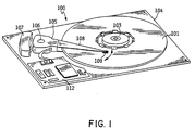
- Fig. 1 shows a magnetic disk drive storage unit 100 in accordance with the preferred embodiment.
- Disk unit 100 comprises rotatable disk 101, which is rigidly attached to hub 103, which is mounted on disk drive base or housing 104. Hub 103 and disk 101 are driven by a drive motor at a constant rotational velocity. The drive motor is contained within hub 103.
- Actuator assembly 105 is situated to one side of disk 101. Actuator 105 rotates through an arc about shaft 106 parallel to the axis of disk 101, driven by electro-magnetic motor 107, to position the transducer heads.
- a cover (not shown) mates with base 104 to enclose and protect the disk and actuator assemblies.
- Circuit cards 112 Electronic modules for controlling the operation of the drive and communicating with another device, such as a host computer, are mounted on a circuit card 112 within the head/disk enclosure formed by base 104 and the cover.
- circuit card 112 is mounted within the enclosure and shaped to take up unused space around the disk in order to conserve space, as would be used for a PCMCIA Type II form factor.
- the card 112 could also be mounted outside the head/disk enclosure, or the base itself could be made as a circuit card for mounting electronic modules directly to it.
- a plurality of head/suspension assemblies 108 are rigidly attached to the prongs of actuator 105.
- An aerodynamic read/write transducer head 109 is located at the end of each head/suspension assembly 108 adjacent the disk surface.
- Hub 103 is a one-piece, integrally-formed part which also contains clamping means for locking disk 101 in place, and which functions as a rotor housing for the drive motor.
- integrally-formed it should be understood that hub 103 is a uniform material formed as a single solid mass by molding, casting, extruding, or other means, and may be machined, etched, or otherwise shaped as necessary to the required dimensions; hub 103 is not built up from multiple discrete components attached together.
- hub 103 is an injection molded polymeric part.
- the polymer be a polyetherimide (PEI), in particular Ultem 7201, which is commercially available from General Electric Corporation. Ultem 7201 is preferred because its coefficient of thermal expansion is close to that of aluminum, the preferred material for disk 101.
- PEI polyetherimide
- Ultem 7201 is preferred because its coefficient of thermal expansion is close to that of aluminum, the preferred material for disk 101.
- other suitable polymers may be used.
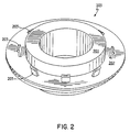
- Fig. 2 is an isometric view of integral hub, clamp and rotor housing 103 according to the preferred embodiment.
- Hub 103 preferably includes a hollow cylindrical base portion 201, a relatively flat cylindrical flange portion 202 extending from base portion 201, and a plurality of circumferentially spaced fingers 203 for engaging disk 101 and serving as a clamping means.
- Fig. 3 is a sectional view, in the plane of the disk axis, of integral hub, clamp and rotor housing 103 according to the preferred embodiment.
- hollow cylindrical base portion 201 defines a central cylindrical hole 301 for the disk shaft and bearings.
- Flange portion 202 extends from approximately the middle of base portion 201.
- a circumferential lip 302 extends downward from the lower surface of flange portion 202, near its outer edge. Lip 302 provides a mating surface and support for a rotor back iron and permanent magnets.
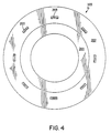
- Fig. 4 is a top view of integral hub, clamp and rotor housing 103 according to the preferred embodiment.
- hub 103 contains eight equally spaced fingers 203 positioned as shown, it being understood that the number and size of the fingers may vary, and that other integral clamping means may be used within the scope of the present invention as defined by the appended claims.
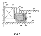
- Fig. 5 shows in greater detail hub 103 and related hardware, including components of the spindle motor, when assembled, in accordance with the preferred embodiment.
- Fig. 5 is a half sectional view, taken in the plane of the axis of rotation of the disks. While hub 103 and related components on only one side of the axis are depicted in Fig. 5, it should be understood that these are symmetrical about the axis.
- Disk shaft 502 is rigidly attached to base 104 of the disk drive.
- Shaft 502 is preferably steel.
- Disk axis 501 runs through the center of shaft 502.
- Hub cylindrical portion 201 is mounted on bearing assembly 504 for rotation about axis 501.
- Bearing assembly preferably comprises two sets of preloaded ball bearings in sealed bearing races, at opposite ends of shaft 502.
- bearing assembly could alternatively be a fluid (hydrodynamic) or other type of bearing.
- portions of bearing assembly 504 may be integrally formed with hub 103, as for example by forming a fluid bearing surface on the inner surface of hub cylindrical portion 201.
- Flange portion 202 of hub 103 extends outward from cylindrical base portion 201 at approximately the middle of its length. Disk 101 rests on the upper surface of flange portion 202, the flange supporting disk 101 from below. Multiple identical circumferentially spaced fingers 203 protrude from the upper surface of flange 202 to engage disk 101 and lock it in place, thus serving as a clamping means and obviating the need for a separately attached clamp.
- Back iron 505 and set of permanent rotor magnets 506 for a brushless DC spindle motor are attached to the underside of flange portion 202 at the outer edge.
- Back iron 505 is a ring of magnetically permeable material, preferably an Fe-Pb alloy.
- Back iron 505 may also be a wound series of laminations forming a ring.
- Magnets 506 are preferably a solid ring of suitable magnetizable material, in which successive arcuate segments are magnetized to alternating magnetic polarity. Magnets 506 thus form a set of permanent arcuate magnets, circumferentially arranged about the disk axis to completely encircle the axis, having alternating polarity.
- Circumferential lip 302 provides support for back iron 505 and magnets 506.
- Back iron 505 is preferably bonded to hub 103 at lip 302 and lower surface of flange 202 using a suitable adhesive. Alternatively, it may be attached to hub 103 during the injection molding process by inserting back iron 505 in the mold cavity and molding hub 103 over back iron 505.
- Permanent magnets 506 are preferably bonded directly to back iron 505 using a suitable adhesive.
- Spindle motor electromagnetic stator 508 is attached to base 104 and positioned underneath flange 202, within the annular space defined by cylindrical base portion 201 at the inner radius and back iron 505 and magnets 506 at the outer radius.
- Stator 508 comprises a set of circumferentially spaced electromagnets (poles) surrounding the disk axis, each pole comprising a wire coil wrapped around a magnetically permeable core.
- Stator 508 is connected to motor drive electronics (not shown) on circuit card 112. In operation, the motor drive electronics sequentially pulse different poles of stator 508 to generate a rotating electromagnetic field, as is known in the art.
- stator 508 is a 3-phase stator having three poles in each phase (total of nine poles), and rotor magnet set 506 comprises twelve magnetic pole segments. However, the number of stator and rotor poles may vary.
- Fig. 6 is a sectional view in the plane of the disk axis of a clamping finger 203, showing the finger in greater detail.
- Finger 203 is molded with a slight outward inclination to apply a small radial force to the inner hole of disk 101.
- the angle of inclination is approximately 3 degrees, i.e. the angle ⁇ in Fig. 6 is approximately 87 degrees, it being understood that the optimum angle will vary with the thickness of the finger and type of material selected.
- a pawl 601 Near the end of finger 203 is a pawl 601 for engaging disk 101.
- Pawl 601 contains chamfered top edge 603 to enable assembly of the disk.
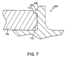
- Fig. 7 is a sectional view of clamping finger 203, showing how it clamps disk 101 in place. Disk 101 and finger 203 are shown in cross-section in the plane of the disk axis.
- Disk 101 preferably contains chamfered inner edges 711,712, which are chamfered at approximately a 45 degree angle. The chamfers make assembly of disk 101 to hub 103 easier, provide a surface for application of force from pawl 601, and help to center the disk.
- Disk 101 is preferably assembled to hub 103 by positioning disk 101 over the fingers and pushing directly downward.
- chamfered edge 712 on the bottom surface of disk 101 slides against chamfered edge 603 on the top surface of pawl 601.
- finger 203 is made from an elastic material, finger 203 retracts inward (toward the disk axis) as disk 101 is pushed down upon it, enabling the narrowest part of the disk center hole to clear the pawl. After the narrowest part of the disk center hole clears the pawl, the finger returns to near its original position due to the natural elasticity of the material.
- pawl 601 will be positioned as shown in Fig. 7, applying a force to chamfered edge 711.
- Pawl 601 applies both a downward axial force and a radial force to chamfered edge 711.
- the downward axial force pushes disk 101 against the upper surface of flange portion 202, securely clamping disk 101 in place.
- finger 203 makes contact with the non-chamfered portion of the inner edge of the hole in disk 101, applying a slight radial force.
- Finger 203 acts as a non-linear beam spring. At rest with the disk in place, the radial force is small to avoid warping the disk. However, the radial force imparted by the finger increases at more than a linear rate if the finger is bent back (in the direction toward the disk axis). As a result, a much stronger force will oppose any movement of the disk from its proper position. The hub therefore achieves a high resistance to mechanical shock with a very low cost, simple design.
- Warpage of disks is a well known problem in the disk drive art.
- a conventional clamp must exert considerable axial force on the clamped disk to ensure that the disk does not move. This force tends to warp the disk.
- the compliant clamping mechanism of the present invention achieves a secure clamping of the disk with virtually no warpage.
- the hub of the present invention is made from a compliant material which is preferably much softer than the disk itself. The surface of the compliant material deforms at the point of contact (i.e., the upper surface of flange portion 202 and fingers 203) with the disk, providing a relatively higher static coefficient of friction than is usually present with the metal-to-metal contact of a conventional disk clamp.
- the disk can be securely clamped using a smaller axial force. Additionally, because the disk material is substantially harder than the hub material, the hub surface rather than the disk surface deforms at the points of contact. The disk accordingly experiences very little local strain near the inner diameter, resulting in very low warpage as compared to a conventional disk.
- finger 203 must be selected for the chosen hub material to provide suitable compliance of the finger, and to simultaneously provide sufficient clamping force when the disk is in place.
- finger 203 is approximately 0.25 mm wide in the radial dimension, and 1 mm wide in the circumferential direction.
- the overall height of the finger is approximately 1 mm. It will be appreciated by those skilled in the art that optimal finger dimensions will vary depending on the qualities of the material. A stiffer hub material may require a thinner finger, and vice-versa. It will further be appreciated that the dimensions will vary depending upon the size and material of the disk itself.
- the dimensions given above for the preferred embodiment are intended for use with a 1.8" (43.22 mm) disk formed of an aluminum substrate, and having a thickness of approximately .635mm, such as would be used for a PCMCIA Type II form factor.
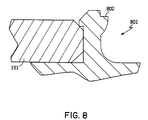
- Fig. 8 is a sectional view of an alternate design for a clamping finger 801 and disk.
- the alternate clamping finger 801 of Fig. 8 is identical to clamping finger 203 described above and shown in Figs. 1-7, except for the addition of a tab 802 projecting from the side of the finger facing the disk axis.
- Tab 802 provides a surface for engagement with a disk removal tool (not shown). To remove disk 101, the tool applies a downward force to tab 802, tending to bend finger 801 backward. At the same time, disk 101 is lifted from the flange portion 202 of hub 103. Removal of a disk is sometimes necessary during rework of a disk drive as part of the manufacturing and testing process.
- the clamping means is a plurality of fingers extending from the upper surface of the flange and engaging the disk.
- any clamping means which is integrally formed with the hub may be used within the scope of the present invention defined by the claims.
- the fingers might extend from some other portion of the hub, such as hollow cylindrical base portion 201. Fingers extending from some other portion, such as the cylindrical portion, might press down on the disk from above.
- the clamping means could be a deformable ring extending from the upper surface of the flange or from the hollow cylindrical portion, or a deformable ring broken at circumferentially spaced intervals for stress relief.
Abstract
Description
Claims (12)
- A rotating disk data storage device (100), comprising:a disk drive base (104);a rotatably mounted disk for recording data, said disk having an axis of rotation and a circular aperture at its center for mounting said disk on a rotatable hub (103);a single-piece integrally-formed hub member (103) for mounting said disk, said hub member being mounted for rotation about said axis, said hub member forming part of a spindle motor rotor (103,505,506), said hub member comprising a support structure (202) for supporting said disk;a set of rotor magnets (506) attached to said hub member;a spindle motor stator (508) attached to said base for driving said rotor magnets;at least one transducer head (109) for reading data stored on said disk; anda moveable actuator (105) mounted on said disk drive base for positioning said transducer head to read data recorded on said disk;characterized in that said hub member also comprises a clamp structure (203) for locking said disk in place.
- The rotating disk data storage device of claim 1, wherein said hub member comprises:a hollow cylindrical portion (201) having an axis coincident with said axis of rotation of said disk, said hollow cylindrical portion surrounding a disk shaft and fitting within said circular aperture of said disk; anda flange portion (202) extending outward from said hollow cylindrical portion, said flange portion being said support structure for supporting said disk.
- The rotating disk data storage device of claim 1 or 2, wherein said clamp structure of said hub member comprises a plurality of circumferentially spaced fingers (203) extending from said flange portion and engaging said disk.
- The rotating disk data storage device of claim 2, wherein said hollow cylindrical portion (201) of said hub member surrounds a set of bearings (504) for mounting said hub member to said disk shaft.
- The rotating disk data storage device of claim 2, wherein said set of rotor magnets (506) is attached to said flange portion near the outer edge thereof, and said stator (508) is positioned surrounding said disk shaft and between said disk shaft and said rotor magnets.
- The rotating disk data storage device of anyone of claims 1 to 5, wherein said hub member is an injection molded polymeric part.
- The rotating disk data storage device of anyone of claims 1 to 6, wherein said hub member is so shaped that said disk is self-centering upon said hub member.
- The rotating disk data storage device of anyone of claims 1 to 5, wherein said hub member is formed from a resilient material, said resilient material being substantially more resilient than said disk.
- The rotating disk data storage device, of claim 3 wherein:each said finger includes a pawl (601) at one end thereof, said fingers extending through said circular aperture of said disk, said pawls engaging said disk and imparting an axial force to said disk forcing said first surface of said disk against said support surface.
- The rotating disk data storage device of claim 9, wherein said aperture of said disk forms an inner surface thereof surrounding said axis of rotation, and wherein said fingers contact said inner surface, each finger thereby imparting a radial force to said disk.
- The rotating disk data storage device of claim 10, wherein a pawls engage said disk along a chamfered edge (711,712) surrounding said circular aperture.
- The rotating disk data storage device of claim 9, wherein each said finger contains a projecting tab (802) for engagement with a disk removal tool, said projecting tab projecting from a side of said finger facing said disk axis.
Applications Claiming Priority (3)
| Application Number | Priority Date | Filing Date | Title |
|---|---|---|---|
| US322716 | 1994-10-12 | ||
| US08/322,716 US5486962A (en) | 1994-10-12 | 1994-10-12 | Integral hub and disk clamp for a disk drive storage device |
| PCT/EP1995/003933 WO1996012278A1 (en) | 1994-10-12 | 1995-10-05 | Integral hub and disk clamp for a disk drive storage device |
Publications (2)
| Publication Number | Publication Date |
|---|---|
| EP0786134A1 EP0786134A1 (en) | 1997-07-30 |
| EP0786134B1 true EP0786134B1 (en) | 1998-06-03 |
Family
ID=23256097
Family Applications (1)
| Application Number | Title | Priority Date | Filing Date |
|---|---|---|---|
| EP95935905A Expired - Lifetime EP0786134B1 (en) | 1994-10-12 | 1995-10-05 | Disk storage device with integral hub and disk clamp |
Country Status (17)
| Country | Link |
|---|---|
| US (3) | US5486962A (en) |
| EP (1) | EP0786134B1 (en) |
| JP (1) | JP2870666B2 (en) |
| KR (1) | KR100238921B1 (en) |
| CN (1) | CN1075656C (en) |
| AT (1) | ATE166995T1 (en) |
| BR (1) | BR9504206A (en) |
| CA (1) | CA2197917A1 (en) |
| CZ (1) | CZ287196B6 (en) |
| DE (1) | DE69502835T2 (en) |
| HU (1) | HU215304B (en) |
| MY (1) | MY121941A (en) |
| PL (1) | PL178338B1 (en) |
| RU (1) | RU2139578C1 (en) |
| SG (1) | SG38839A1 (en) |
| TW (1) | TW351805B (en) |
| WO (1) | WO1996012278A1 (en) |
Families Citing this family (38)
| Publication number | Priority date | Publication date | Assignee | Title |
|---|---|---|---|---|
| US5486962A (en) | 1994-10-12 | 1996-01-23 | International Business Machines Corporation | Integral hub and disk clamp for a disk drive storage device |
| US5596462A (en) * | 1994-11-29 | 1997-01-21 | International Business Machines Corporation | Data storage disk clamp apparatus for minimizing disk clamping force and surface area |
| EP0747897A3 (en) * | 1995-06-06 | 1997-08-06 | Iomega Corp | Disk cartridge hub locking mechanism |
| US6084319A (en) * | 1996-10-16 | 2000-07-04 | Canon Kabushiki Kaisha | Linear motor, and stage device and exposure apparatus provided with the same |
| JP3011910B2 (en) * | 1997-09-19 | 2000-02-21 | 株式会社ケンウッド | Disk clamp mechanism of disk drive |
| US6741544B1 (en) * | 1997-09-25 | 2004-05-25 | Matsushita Electric Industrial Co., Ltd. | Disk drive apparatus |
| US6130801A (en) * | 1997-11-07 | 2000-10-10 | Seagate Technology, Inc. | Composite disc spacer for a disc drive |
| US6212031B1 (en) * | 1997-11-24 | 2001-04-03 | Seagate Technology Llc | Radially-loaded, snap-fit disc mounting system for a disc drive |
| TW420347U (en) * | 1999-01-11 | 2001-01-21 | Sunonwealth Electr Mach Ind Co | Transfer system structure of main axis motor for CD-ROM drive |
| GB2347551B (en) * | 1999-03-01 | 2003-05-07 | Sunonwealth Electr Mach Ind Co | Support structure for a spindle motor of a compact disc machine |
| US6519113B1 (en) * | 1999-04-28 | 2003-02-11 | Seagate Technology Llc | Spindle motor assembly with polymeric motor shaft and hub for rotating a data storage disk |
| US6304412B1 (en) | 1999-05-12 | 2001-10-16 | Maxtor Corporation | Disk drive with interlocking disk clamp |
| US6579958B2 (en) | 1999-12-07 | 2003-06-17 | The Dow Chemical Company | Superabsorbent polymers having a slow rate of absorption |
| KR20010000390A (en) * | 2000-09-26 | 2001-01-05 | 이영준 | Skin Improvement Composition Including Anti-Aging and Anti-Acne with Kimchi Extract |
| US6757132B1 (en) | 2000-12-27 | 2004-06-29 | Western Digital Technologies, Inc. | Disk drive comprising a snap-on disk clamp |
| JP2002312999A (en) * | 2001-04-16 | 2002-10-25 | Mitsumi Electric Co Ltd | Disk unit |
| US6798614B2 (en) | 2001-06-01 | 2004-09-28 | Seagate Technology Llc | Releasable disc clamping assembly |
| US6898050B2 (en) * | 2002-02-21 | 2005-05-24 | Seagate Technology Llc | Hydrodynamic bearing motor having a molded plastic hub |
| US6703584B2 (en) | 2002-05-13 | 2004-03-09 | Seagate Technology Llc | Disc clamp adjustment using heat |
| US6771461B2 (en) * | 2002-06-21 | 2004-08-03 | Seagate Technology Llc | Spindle hub having a back iron mountingly coupled to only a hub separating member |
| CN100369362C (en) * | 2002-11-23 | 2008-02-13 | 深圳易拓科技有限公司 | Method for mfg of stator of disc driver motor |
| US6876517B2 (en) * | 2003-03-10 | 2005-04-05 | Esgw Holdings Limited | Data storage device with spindle motor |
| KR100513315B1 (en) * | 2003-04-28 | 2005-09-09 | 삼성전기주식회사 | a holder for disc driver |
| JP2007516426A (en) * | 2003-05-16 | 2007-06-21 | ユニバーシティー オブ ロチェスター | Colorimetric and fluorescent methods for the detection of oligonucleotides |
| JP2005209312A (en) * | 2004-01-26 | 2005-08-04 | Matsushita Electric Ind Co Ltd | Disk holder and disk changer device |
| KR100555549B1 (en) * | 2004-01-28 | 2006-03-03 | 삼성전자주식회사 | Apparatus for clamping disk of hard disk drive |
| SG118231A1 (en) * | 2004-03-02 | 2006-01-27 | Seagate Technology Llc | A clamp or clamp assembly having a low profile |
| US7412713B2 (en) * | 2004-03-04 | 2008-08-12 | Matsushita Electric Industrial Co., Ltd. | Chucking apparatus |
| JP2005251303A (en) * | 2004-03-04 | 2005-09-15 | Matsushita Electric Ind Co Ltd | Chucking apparatus |
| WO2005086152A1 (en) * | 2004-03-04 | 2005-09-15 | Matsushita Electric Industrial Co., Ltd. | Chucking device |
| US20050201010A1 (en) * | 2004-03-12 | 2005-09-15 | Yiren Hong | Disc media retainer |
| KR100604861B1 (en) * | 2004-05-29 | 2006-07-31 | 삼성전자주식회사 | Disk spacer and spindle motor assembly having the same |
| US7334243B2 (en) * | 2005-08-30 | 2008-02-19 | Delphi Technologies, Inc. | Vane integration into motor hub to enhance CD cooling |
| JP2008217840A (en) * | 2007-02-28 | 2008-09-18 | Matsushita Electric Ind Co Ltd | Spindle motor, and recording and reproducing device using it |
| US8261432B2 (en) * | 2008-07-24 | 2012-09-11 | Hitachi Global Storage Technologies, Netherlands B.V. | Disk spacer drop-proofing tool for disk removal process |
| US8322021B1 (en) | 2008-07-31 | 2012-12-04 | Western Digital Technologies, Inc. | Method of manufacturing a disk drive |
| DE202010008999U1 (en) | 2010-11-10 | 2011-04-28 | Huang, Han-Ching | Device for tensioning two straps |
| US8493820B1 (en) * | 2012-05-25 | 2013-07-23 | Timothy Edward Langlais | Matched CTE drive |
Family Cites Families (27)
| Publication number | Priority date | Publication date | Assignee | Title |
|---|---|---|---|---|
| US4358843A (en) * | 1980-09-29 | 1982-11-09 | Rager Edgar A | Spindle for centering a data disk |
| JPS5958678A (en) * | 1982-09-29 | 1984-04-04 | Canon Electronics Inc | Magnetic disc device |
| US4585963A (en) * | 1982-11-01 | 1986-04-29 | Storage Technology Partners Ii | Brushless direct current motor with inverted magnet clip |
| JPS60237672A (en) * | 1984-05-11 | 1985-11-26 | Hitachi Ltd | Fixing mechanism for disk |
| NL8503523A (en) * | 1985-12-20 | 1987-07-16 | Philips Nv | DEVICE FOR CENTERING A ROTATING PLATE DURING OPERATION. |
| JPH0526915Y2 (en) * | 1986-10-29 | 1993-07-08 | ||
| NL8700819A (en) * | 1987-04-08 | 1988-11-01 | Philips Nv | DEVICE FOR RECORDING OR READING INFORMATION FROM AN INFORMATION PLATE. |
| JP2699472B2 (en) * | 1988-10-28 | 1998-01-19 | 日本電気株式会社 | Spindle hub for magnetic disk drive |
| US5157295A (en) * | 1989-01-25 | 1992-10-20 | Conner Peripherals, Inc. | Under-the-hub disk drive spin motor |
| JPH02252180A (en) * | 1989-03-27 | 1990-10-09 | Kubota Micro Dain Kk | Memory disk device |
| US5014143A (en) * | 1989-03-31 | 1991-05-07 | Hitachi Electronics Engineering Co., Ltd. | Data recording disk chuck mechanism |
| US4965476A (en) * | 1989-04-20 | 1990-10-23 | Conner Peripherals, Inc. | Stabilized disk drive spin motor |
| JP2946540B2 (en) * | 1989-08-16 | 1999-09-06 | ソニー株式会社 | motor |
| US5048005A (en) * | 1989-10-10 | 1991-09-10 | Ekhoff Donald L | Spindle clamp having a unitary lock member |
| US5193084A (en) * | 1989-11-15 | 1993-03-09 | U.S. Philips Corporation | Device for rotating a disc-shaped information carrier including a turntable and frame |
| JP2861144B2 (en) * | 1989-11-16 | 1999-02-24 | ソニー株式会社 | Disc chucking mechanism |
| JPH0380549U (en) * | 1989-12-04 | 1991-08-19 | ||
| FR2666842B1 (en) * | 1990-09-17 | 1992-11-20 | Somfy | WINDING DEVICE WITH TUBULAR MOTOR FOR BLINDS, ROLLER SHUTTERS OR THE LIKE. |
| JP3384002B2 (en) * | 1992-01-24 | 2003-03-10 | ソニー株式会社 | Disc table and recording and / or reproducing apparatus |
| US5243481A (en) * | 1991-09-25 | 1993-09-07 | Integral Peripherals, Inc. | Clamp for information storage disk |
| WO1993006600A1 (en) * | 1991-09-25 | 1993-04-01 | Integral Peripherals, Inc. | Architecture for low-profile rigid disk drive |
| JP3351545B2 (en) * | 1991-10-01 | 2002-11-25 | 日本電産株式会社 | Hard disk drive |
| JPH06131783A (en) * | 1992-10-19 | 1994-05-13 | Asahi Corp:Kk | Disk holder |
| JP3312942B2 (en) * | 1993-02-23 | 2002-08-12 | ミネベア株式会社 | Magnetic disk drive |
| US5774445A (en) * | 1993-08-09 | 1998-06-30 | Funai Electric Co., Ltd. | Disc clamp mechanism having radial disposed disc pressing elements |
| JPH07105607A (en) * | 1993-10-07 | 1995-04-21 | Akai Electric Co Ltd | Disk adapter |
| US5486962A (en) * | 1994-10-12 | 1996-01-23 | International Business Machines Corporation | Integral hub and disk clamp for a disk drive storage device |
-
1994
- 1994-10-12 US US08/322,716 patent/US5486962A/en not_active Expired - Lifetime
-
1995
- 1995-01-26 TW TW084100714A patent/TW351805B/en not_active IP Right Cessation
- 1995-04-26 MY MYPI95001096A patent/MY121941A/en unknown
- 1995-04-27 CN CN95105030A patent/CN1075656C/en not_active Expired - Fee Related
- 1995-04-28 SG SG1995000357A patent/SG38839A1/en unknown
- 1995-09-28 BR BR9504206A patent/BR9504206A/en not_active Application Discontinuation
- 1995-09-29 KR KR1019950034033A patent/KR100238921B1/en not_active IP Right Cessation
- 1995-10-05 HU HU9701245A patent/HU215304B/en not_active IP Right Cessation
- 1995-10-05 RU RU97107356A patent/RU2139578C1/en not_active IP Right Cessation
- 1995-10-05 AT AT95935905T patent/ATE166995T1/en not_active IP Right Cessation
- 1995-10-05 JP JP8512902A patent/JP2870666B2/en not_active Expired - Lifetime
- 1995-10-05 WO PCT/EP1995/003933 patent/WO1996012278A1/en active IP Right Grant
- 1995-10-05 CA CA002197917A patent/CA2197917A1/en not_active Abandoned
- 1995-10-05 DE DE69502835T patent/DE69502835T2/en not_active Expired - Fee Related
- 1995-10-05 CZ CZ199788A patent/CZ287196B6/en not_active IP Right Cessation
- 1995-10-05 EP EP95935905A patent/EP0786134B1/en not_active Expired - Lifetime
- 1995-10-05 PL PL95319484A patent/PL178338B1/en not_active IP Right Cessation
-
1996
- 1996-08-27 US US08/703,621 patent/US5872681A/en not_active Expired - Lifetime
-
1998
- 1998-06-09 US US09/094,067 patent/US6556376B1/en not_active Expired - Fee Related
Also Published As
| Publication number | Publication date |
|---|---|
| RU2139578C1 (en) | 1999-10-10 |
| WO1996012278A1 (en) | 1996-04-25 |
| US5486962A (en) | 1996-01-23 |
| CN1127401A (en) | 1996-07-24 |
| EP0786134A1 (en) | 1997-07-30 |
| PL178338B1 (en) | 2000-04-28 |
| DE69502835T2 (en) | 1999-02-18 |
| DE69502835D1 (en) | 1998-07-09 |
| JP2870666B2 (en) | 1999-03-17 |
| CN1075656C (en) | 2001-11-28 |
| ATE166995T1 (en) | 1998-06-15 |
| US6556376B1 (en) | 2003-04-29 |
| US5872681A (en) | 1999-02-16 |
| KR960015166A (en) | 1996-05-22 |
| PL319484A1 (en) | 1997-08-04 |
| BR9504206A (en) | 1997-04-01 |
| SG38839A1 (en) | 1997-04-17 |
| HUT76704A (en) | 1997-10-28 |
| JPH10504419A (en) | 1998-04-28 |
| CZ287196B6 (en) | 2000-10-11 |
| CZ8897A3 (en) | 1997-06-11 |
| TW351805B (en) | 1999-02-01 |
| MY121941A (en) | 2006-03-31 |
| HU215304B (en) | 1998-11-30 |
| CA2197917A1 (en) | 1996-04-25 |
| KR100238921B1 (en) | 2000-01-15 |
Similar Documents
| Publication | Publication Date | Title |
|---|---|---|
| EP0786134B1 (en) | Disk storage device with integral hub and disk clamp | |
| US6222291B1 (en) | Electric motor having axially centered ball bearings | |
| US5590004A (en) | Resilient clamp and compliant element data disk support system | |
| US7518823B2 (en) | Spindle motor winding for miniature hard disk drive | |
| US5251082A (en) | Miniaturized disk file pluggable into a card terminal | |
| US6724567B1 (en) | Radially loaded disc mounting system for a disc drive | |
| US6172844B1 (en) | Double grooved spacer for a disc drive | |
| US6603636B2 (en) | Apparatus for centering a disc clamp on a disc pack in a disc drive | |
| US5486961A (en) | Resilient compliant clamp for data storage disk drives | |
| US6567238B1 (en) | Disc clamp for a disc drive | |
| US6417988B1 (en) | Disc clamp for a disc drive | |
| US6282054B1 (en) | Teeth lock ring for a disc stack | |
| KR100433865B1 (en) | Spindle motor assembly and a method of securing an information storage disc within disc drive | |
| US6115222A (en) | Single, central limit stop for a disc drive actuator | |
| US5917677A (en) | Disk drive motor spindle hub assembly with separately formed hub ceramic flange attachment | |
| JPH0729295A (en) | Disk drive device | |
| GB2345796A (en) | Permanent magnet for an actuator and a method of making the same | |
| US4829657A (en) | In-spindle motor assembly for disk drive and method for fabricating the same | |
| US20030002206A1 (en) | Air razor and disk limiter for a hard disk drive | |
| KR20000028988A (en) | Voice coil motor latch housing for hard disk drive and manufacturing method thereof | |
| JPH10222926A (en) | Disc clamp mechanism for optical disc player |
Legal Events
| Date | Code | Title | Description |
|---|---|---|---|
| PUAI | Public reference made under article 153(3) epc to a published international application that has entered the european phase |
Free format text: ORIGINAL CODE: 0009012 |
|
| 17P | Request for examination filed |
Effective date: 19970410 |
|
| AK | Designated contracting states |
Kind code of ref document: A1 Designated state(s): AT BE CH DE ES FR GB IE IT LI NL SE |
|
| GRAG | Despatch of communication of intention to grant |
Free format text: ORIGINAL CODE: EPIDOS AGRA |
|
| 17Q | First examination report despatched |
Effective date: 19970821 |
|
| GRAG | Despatch of communication of intention to grant |
Free format text: ORIGINAL CODE: EPIDOS AGRA |
|
| GRAH | Despatch of communication of intention to grant a patent |
Free format text: ORIGINAL CODE: EPIDOS IGRA |
|
| GRAH | Despatch of communication of intention to grant a patent |
Free format text: ORIGINAL CODE: EPIDOS IGRA |
|
| GRAA | (expected) grant |
Free format text: ORIGINAL CODE: 0009210 |
|
| AK | Designated contracting states |
Kind code of ref document: B1 Designated state(s): AT BE CH DE ES FR GB IE IT LI NL SE |
|
| PG25 | Lapsed in a contracting state [announced via postgrant information from national office to epo] |
Ref country code: NL Free format text: LAPSE BECAUSE OF FAILURE TO SUBMIT A TRANSLATION OF THE DESCRIPTION OR TO PAY THE FEE WITHIN THE PRESCRIBED TIME-LIMIT Effective date: 19980603 Ref country code: LI Free format text: LAPSE BECAUSE OF FAILURE TO SUBMIT A TRANSLATION OF THE DESCRIPTION OR TO PAY THE FEE WITHIN THE PRESCRIBED TIME-LIMIT Effective date: 19980603 Ref country code: ES Free format text: THE PATENT HAS BEEN ANNULLED BY A DECISION OF A NATIONAL AUTHORITY Effective date: 19980603 Ref country code: CH Free format text: LAPSE BECAUSE OF FAILURE TO SUBMIT A TRANSLATION OF THE DESCRIPTION OR TO PAY THE FEE WITHIN THE PRESCRIBED TIME-LIMIT Effective date: 19980603 Ref country code: BE Free format text: LAPSE BECAUSE OF FAILURE TO SUBMIT A TRANSLATION OF THE DESCRIPTION OR TO PAY THE FEE WITHIN THE PRESCRIBED TIME-LIMIT Effective date: 19980603 Ref country code: AT Free format text: LAPSE BECAUSE OF FAILURE TO SUBMIT A TRANSLATION OF THE DESCRIPTION OR TO PAY THE FEE WITHIN THE PRESCRIBED TIME-LIMIT Effective date: 19980603 |
|
| REF | Corresponds to: |
Ref document number: 166995 Country of ref document: AT Date of ref document: 19980615 Kind code of ref document: T |
|
| REG | Reference to a national code |
Ref country code: CH Ref legal event code: NV Representative=s name: CARL O. BARTH C/O IBM CORPORATION ZURICH INTELLECT Ref country code: CH Ref legal event code: EP |
|
| REF | Corresponds to: |
Ref document number: 69502835 Country of ref document: DE Date of ref document: 19980709 |
|
| ITF | It: translation for a ep patent filed |
Owner name: BRAVI ALFREDO DR. |
|
| REG | Reference to a national code |
Ref country code: IE Ref legal event code: FG4D |
|
| PG25 | Lapsed in a contracting state [announced via postgrant information from national office to epo] |
Ref country code: SE Free format text: LAPSE BECAUSE OF FAILURE TO SUBMIT A TRANSLATION OF THE DESCRIPTION OR TO PAY THE FEE WITHIN THE PRESCRIBED TIME-LIMIT Effective date: 19980903 |
|
| ET | Fr: translation filed | ||
| NLV1 | Nl: lapsed or annulled due to failure to fulfill the requirements of art. 29p and 29m of the patents act | ||
| REG | Reference to a national code |
Ref country code: CH Ref legal event code: PL |
|
| PLBE | No opposition filed within time limit |
Free format text: ORIGINAL CODE: 0009261 |
|
| STAA | Information on the status of an ep patent application or granted ep patent |
Free format text: STATUS: NO OPPOSITION FILED WITHIN TIME LIMIT |
|
| 26N | No opposition filed | ||
| REG | Reference to a national code |
Ref country code: GB Ref legal event code: IF02 |
|
| REG | Reference to a national code |
Ref country code: GB Ref legal event code: 732E |
|
| REG | Reference to a national code |
Ref country code: FR Ref legal event code: TP |
|
| PGFP | Annual fee paid to national office [announced via postgrant information from national office to epo] |
Ref country code: IE Payment date: 20070917 Year of fee payment: 13 |
|
| PGFP | Annual fee paid to national office [announced via postgrant information from national office to epo] |
Ref country code: IT Payment date: 20071030 Year of fee payment: 13 |
|
| PGFP | Annual fee paid to national office [announced via postgrant information from national office to epo] |
Ref country code: GB Payment date: 20071031 Year of fee payment: 13 Ref country code: FR Payment date: 20071026 Year of fee payment: 13 |
|
| PGFP | Annual fee paid to national office [announced via postgrant information from national office to epo] |
Ref country code: DE Payment date: 20071206 Year of fee payment: 13 |
|
| GBPC | Gb: european patent ceased through non-payment of renewal fee |
Effective date: 20081005 |
|
| REG | Reference to a national code |
Ref country code: IE Ref legal event code: MM4A |
|
| REG | Reference to a national code |
Ref country code: FR Ref legal event code: ST Effective date: 20090630 |
|
| PG25 | Lapsed in a contracting state [announced via postgrant information from national office to epo] |
Ref country code: IT Free format text: LAPSE BECAUSE OF NON-PAYMENT OF DUE FEES Effective date: 20081005 Ref country code: DE Free format text: LAPSE BECAUSE OF NON-PAYMENT OF DUE FEES Effective date: 20090501 |
|
| PG25 | Lapsed in a contracting state [announced via postgrant information from national office to epo] |
Ref country code: IE Free format text: LAPSE BECAUSE OF NON-PAYMENT OF DUE FEES Effective date: 20081006 Ref country code: FR Free format text: LAPSE BECAUSE OF NON-PAYMENT OF DUE FEES Effective date: 20081031 |
|
| PG25 | Lapsed in a contracting state [announced via postgrant information from national office to epo] |
Ref country code: GB Free format text: LAPSE BECAUSE OF NON-PAYMENT OF DUE FEES Effective date: 20081005 |