EP0776850A2 - Cabines d'ascenseur transférées horizontalement entre des ascenseurs à double ponts - Google Patents
Cabines d'ascenseur transférées horizontalement entre des ascenseurs à double ponts Download PDFInfo
- Publication number
- EP0776850A2 EP0776850A2 EP96308647A EP96308647A EP0776850A2 EP 0776850 A2 EP0776850 A2 EP 0776850A2 EP 96308647 A EP96308647 A EP 96308647A EP 96308647 A EP96308647 A EP 96308647A EP 0776850 A2 EP0776850 A2 EP 0776850A2
- Authority
- EP
- European Patent Office
- Prior art keywords
- car
- deck
- cab
- transfer
- car frame
- Prior art date
- Legal status (The legal status is an assumption and is not a legal conclusion. Google has not performed a legal analysis and makes no representation as to the accuracy of the status listed.)
- Withdrawn
Links
Images


Classifications
-
- B—PERFORMING OPERATIONS; TRANSPORTING
- B66—HOISTING; LIFTING; HAULING
- B66B—ELEVATORS; ESCALATORS OR MOVING WALKWAYS
- B66B9/00—Kinds or types of lifts in, or associated with, buildings or other structures
-
- B—PERFORMING OPERATIONS; TRANSPORTING
- B66—HOISTING; LIFTING; HAULING
- B66B—ELEVATORS; ESCALATORS OR MOVING WALKWAYS
- B66B1/00—Control systems of elevators in general
- B66B1/02—Control systems without regulation, i.e. without retroactive action
- B66B1/06—Control systems without regulation, i.e. without retroactive action electric
- B66B1/14—Control systems without regulation, i.e. without retroactive action electric with devices, e.g. push-buttons, for indirect control of movements
- B66B1/18—Control systems without regulation, i.e. without retroactive action electric with devices, e.g. push-buttons, for indirect control of movements with means for storing pulses controlling the movements of several cars or cages
-
- B—PERFORMING OPERATIONS; TRANSPORTING
- B66—HOISTING; LIFTING; HAULING
- B66B—ELEVATORS; ESCALATORS OR MOVING WALKWAYS
- B66B1/00—Control systems of elevators in general
- B66B1/24—Control systems with regulation, i.e. with retroactive action, for influencing travelling speed, acceleration, or deceleration
- B66B1/2408—Control systems with regulation, i.e. with retroactive action, for influencing travelling speed, acceleration, or deceleration where the allocation of a call to an elevator car is of importance, i.e. by means of a supervisory or group controller
- B66B1/2458—For elevator systems with multiple shafts and a single car per shaft
-
- B—PERFORMING OPERATIONS; TRANSPORTING
- B66—HOISTING; LIFTING; HAULING
- B66B—ELEVATORS; ESCALATORS OR MOVING WALKWAYS
- B66B1/00—Control systems of elevators in general
- B66B1/24—Control systems with regulation, i.e. with retroactive action, for influencing travelling speed, acceleration, or deceleration
- B66B1/2408—Control systems with regulation, i.e. with retroactive action, for influencing travelling speed, acceleration, or deceleration where the allocation of a call to an elevator car is of importance, i.e. by means of a supervisory or group controller
- B66B1/2491—For elevator systems with lateral transfers of cars or cabins between hoistways
-
- B—PERFORMING OPERATIONS; TRANSPORTING
- B66—HOISTING; LIFTING; HAULING
- B66B—ELEVATORS; ESCALATORS OR MOVING WALKWAYS
- B66B9/00—Kinds or types of lifts in, or associated with, buildings or other structures
- B66B9/003—Kinds or types of lifts in, or associated with, buildings or other structures for lateral transfer of car or frame, e.g. between vertical hoistways or to/from a parking position
-
- B—PERFORMING OPERATIONS; TRANSPORTING
- B66—HOISTING; LIFTING; HAULING
- B66B—ELEVATORS; ESCALATORS OR MOVING WALKWAYS
- B66B2201/00—Aspects of control systems of elevators
- B66B2201/30—Details of the elevator system configuration
- B66B2201/303—Express or shuttle elevators
-
- B—PERFORMING OPERATIONS; TRANSPORTING
- B66—HOISTING; LIFTING; HAULING
- B66B—ELEVATORS; ESCALATORS OR MOVING WALKWAYS
- B66B2201/00—Aspects of control systems of elevators
- B66B2201/30—Details of the elevator system configuration
- B66B2201/304—Transit control
-
- B—PERFORMING OPERATIONS; TRANSPORTING
- B66—HOISTING; LIFTING; HAULING
- B66B—ELEVATORS; ESCALATORS OR MOVING WALKWAYS
- B66B2201/00—Aspects of control systems of elevators
- B66B2201/30—Details of the elevator system configuration
- B66B2201/306—Multi-deck elevator cars
Definitions
- This invention relates to elevator systems.
- an elevator cab may be moved in a first car frame in a first hoistway, from the ground floor up to a transfer floor, moved horizontally into a second elevator car frame in a second hoistway, and moved therein upwardly in the building, and so forth, as disclosed in a our International patent application No. PCT/US96/17040, a copy of which is in the file of the present application.
- PCT/US96/17040 a copy of which is in the file of the present application.
- only a single cab is moving at any time, while any other car frames are idly waiting in the hoistways. Therefore, the aforementioned system while being useful to reach great heights in the building, is wasteful of core.
- Objects of the invention include improving the utilization of elevator hoistways in which horizontally moveable elevator cabs are transferred from a car frame in one hoistway to a car frame in another hoistway.
- adjacent, overlapping elevator hoistways have double deck car frames therein, a cab being transferred from the lower deck of one car frame to a lower deck of the other car frame as a cab is transferred from the upper deck of the other car frame to the upper deck of the one car frame.
- the cabs may be transferred in the upper and lower decks simultaneously.
- the invention provides greater utilization of the elevator hoistways in the building while permitting elevator cabs to be moved two or more times the practical length of conventional elevators.
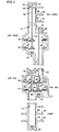
- Fig. 1 is a simplified, stylized, partial, sectioned, side elevation view of an elevator shuttle system in accordance with the invention.
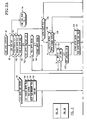
- Fig. 2 is a logic flow diagram illustrating a portion of a routine which may be used for controlling car one in the lowest shaft of Fig. 1, with a cab in its upper deck.
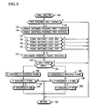
- Fig. 3 is a logic flow diagram illustrating a subroutine for controlling a run of car one.
- Fig. 4 is a logic flow diagram illustrating a portion of a routine which may be used for controlling car two in the middle shaft of Fig. 1, with a cab in its upper deck.
- Fig. 5 is a logic flow diagram illustrating a routine which may be used to synchronize two cars approaching a transfer landing.
- Fig. 6 is a simplified side elevation view of car frames and a cab, illustrating a second horizontal motive means which the invention may use.
- an elevator system comprises three separate hoistways 19-21 each of which contains a complete elevator, except for the passenger-containing cab portions, there being a pair of cabs 22, 23 which are transferred between the three hoistways 19-21.
- Each elevator includes a double deck frame 26-28, hoist ropes 30-32, a hoisting machine 34-36, including a motor, a sheave and a brake, disposed in a machine room 37-39 along with a car controller 40-42.
- the elevators in hoistways 19-21 are referred to as car one, car two and car three, respectively.
- Car one carries passengers between a pair of lobby floors 45, 46 and a first pair of transfer floors 47, 48, which represent a "transfer" floor for car one and a “low” floor for car two.
- Car two carries passengers from the first transfer floors 47, 48 to a second pair of transfer floors 49, 50.
- Car three transfers passengers between the second pair of transfer floors 49, 50 and a pair of upper lobby floors 51, 52, sometimes referred to as a "sky lobby", which may be a restaurant floor, an observation floor, or a lobby from which passengers may embark to still higher (or lower) floors by means of local elevators (with or without express runs).
- Access between the elevator cabs 22, 23 and the lobby floors 45, 46, 51, 52 is provided by hoistway doors 55-58, respectively.
- each hoistway 19-21 may contain a buffer 60-62, as is known.
- Each elevator may have other equipment, such as a counterweight, governor, safeties and the like, known in double deck elevators, none of which are special for the present invention and therefore need not be shown herein.
- each transfer floor there are provided horizontal motive means, such as jack screw assemblies 64-71 for transferring the cabs 22, 23 from one frame 26-28 of one of the cars to a frame of another of the cars, as illustrated more fully in our above-mentioned co-pending International application, or such as is described with respect to Fig. 6 hereinafter.
- the cabs 22-23 are disposed on wheels to permit rolling the cabs from a platform of one frame 26-28 to a platform of another frame 26-28.
- the cabs 22-23 have doors of the usual type (on the righthand side as shown in Fig. 1) operated by a door operating mechanism to allow passenger access to the lower and upper lobby floors 45, 46, 51, 52. However, the doors are not opened at the transfer floors 47-50.
- Each of the cars is provided with floor locks which may, in this embodiment, simply comprise bistable solenoid plungers which can be moved into a locked position, where the plunger engages a plate supported in the hoistway, as shown in said co-pending application.
- bistable solenoid allows energizing one coil to cause the plunger to engage as shown, after which the coil can be disenergized and the plunger will remain engaged; when the car is to move, the opposite coil can be operated to move the plunger out of engagement, and thereafter the plunger will remain out of engagement until the other coil is once again operated.
- the use of the floor locks is to reduce erratic motion of the car frames 26-28 due to variations in rope stretch, as the cabs are transferred from one frame to the other and vice versa.
- the plate may be combined with a sill (only one sill 60 being identified in Fig. 1) that allows the cabs 22, 23 to roll between car frames 26-28.
- Each of the car frames 26-28 also has a cab/car lock system which may comprise plungers which can move inwardly toward the cab so as to engage plates on the cab, as shown in said co-pending application, but not shown herein.
- Each frame also has some form of proximity detector which can sense the presence of an element on each cab 22, 23 to provide a signal generally indicative of the fact that the cab is on a particular deck of a particular car, as shown in said co-pending application.
- power for lighting and circuits for the signals referred to hereinbefore may be maintained by means of umbilical cables which have two sided plug-socket assemblies which mate with corresponding socket/plug assemblies attached to respective booms which are controlled by boom rotating mechanisms on the respective frames, as shown in said aforementioned application.
- the socket/plug assembly of each cab is engaged with either one or the other or both of the socket/plug assemblies of one or two booms on the car frames at all times.
- the socket/plug assemblies on each of the booms each have a monostable solenoid plunger disposed therein which, in response to a release signal, will push the corresponding socket/plug assembly away from the socket/plug assembly of the cab, so as to disengage therefrom, thereby permitting the boom to be retracted when not in use.
- the shaft 21 is disposed to the left of the shaft 20, immediately above the shaft 19.
- each of the shafts 20, 21 could be offset to the right of the shaft below it, as in said aforementioned copending application, if desired.
- Such a choice depends on building design criteria unrelated to the elevators. If such were the case, car two would only need a second boom to interact with the boom on car three.
- the best mode for locking the frame to the floor might be that disclosed in our European patent application claiming priority of U.S. patent application Serial No. 08/565,648 and filed contemporaneously herewith.
- the best mode for locking the cab in a frame during car travel might be that disclosed in our European patent application claiming priority of U.S. patent application Serial No.
- a control routine for car one may be implemented in a microprocessor which performs a variety of functions, not all of which are illustrated herein.
- the function may include door control for the cabs; upper and lower deck cab transfer and door controls, run controls, and motion control for any or all of the cars.
- the routine of Fig. 2 may be reached through an entry point 81 and a first test 82 determines if the car has motion direction commanded to it (that is, the command to go up or down). Assume that an elevator cab is in the upper deck of car one standing at the upper deck 46 of the lower lobby floor, with its doors fully open.
- test 82 will reach a test 83 to see if the position of the car is the transfer floor.
- the transfer floor means that the car is positioned with its upper and lower decks adjacent to the transfer floors 47, 48.
- a negative result of test 83 reaches a subroutine 84 (which may be the same as steps and tests 95-109 of the aforementioned International application, beginning with the doors fully open, controls the closing of the cab doors. It will take many subsequent passes through the subroutine of Fig. 2 to ultimately close the doors; while this occurs, other programming is reached, repetitively through a return point 85.
- a step 90 sets a transfer upper flag; this flag is set to keep track of the fact that when the car arrives at a transfer floor, it has the cab and must transfer it to the other car.
- a step 91 resets the lower lobby corridor lantern, a step 92 sets-the target floor to be the transfer level, and a step 93 sets the car direction command to up. Then other programming is reached through the return point 85.
- test 82 is affirmative so a run subroutine for car one is reached in Fig. 3 through a transfer point 94.
- a first test 95 is reached to determine if the car has a run command yet or not. Initially it will not have, so a negative result of test 95 reaches a pair of tests 96, 97 to see if either an upper cab/car lock or a lower car/cab lock is indeed locked. This may be a safety signal conducted by microswitches or contacts associated with the lock plungers referred to hereinbefore.
- the cab is locked to car one when it first enters the car (step 169, hereinafter), and remains locked until it is transferred to car two again (step 140, hereinafter). If the cab is locked, a pair of tests 98 determine if both the upper and lower car one booms are retracted.
- test 103 determines if the car is still locked to the floor. Initially, it is, so an affirmative result of test 103 reaches a step 104 to reset the car/floor lock, thereby retrieving the lock plungers.
- test 103 is negative and a pre-torque subroutine 105 is reached in which the elevator motor is supplied with proper current so as to support the elevator load in anticipation of lifting the brake. And then a step 106 orders the brake to be lifted and a step 107 sets the elevator into the run mode. Thereafter, the computer reverts to other programming through the return point 102.
- the car motion controller part of the car control 40 (Fig. 1), will cause the car to move in response to a speed profile (or otherwise), in the usual way.
- test 109 determines if the car direction is down. If it is, a test 110 determines if the car has reached the stop control point (SCP) for the target floor (the floor below the lobby) or not. If it has, a step 111 will operate the lantern (not shown herein) at the lower deck 45 of the lobby floor. If the car has not reached the stop control point, the routine bypasses the step 111 and reaches a test 112 to determine if the car has reached the inner door zone (IDZ); prior to reaching a stop control point, test 112 will naturally be negative, causing other programming to be reached through the return point 102.
- SCP stop control point
- IDZ inner door zone
- test 110 will be affirmative so that step 122 will operate the lobby lantern (including a gong) in the usual fashion.
- a test 113 determines if the car has reached an outer door zone (ODZ); initially it will not, so the program will advance through negative results of test 113 and 112 to the return point 102.
- OZ outer door zone
- the car will reach the outer door zone, and a later pass through the routine of Fig. 3 will cause an affirmative result of test 113 to reach a step 114 which directs the doors to become open, in the usual fashion.
- test 112 is reached and, initially, a negative result will cause other programming to be reached through the return point 102.
- an affirmative result of test 112 causes a test 115 to determine if the secondary position transducer (SPT) has indicated that the car is suitably level at a lobby floor. If not, a negative result of test 115 reaches a subroutine 116 to relevel the car, in the usual fashion. When the car is level, an affirmative result of test 115 reaches a test 117 to ensure that the car speed is zero, which might not occur for some number of milliseconds and therefore for a few passes through the routine of Fig. 3.
- SPT secondary position transducer
- the elevator is running in response to the speed profile routine portion of the car controller 40, which brings the car to a complete stop at the floor; and it may be operated in response to the releveling subroutine 116.
- a pass through the routine of Fig. 3 will have an affirmative result of test 117 which reaches a step 121 to reset the lift brake command, thereby allowing the brake to fall and arrest all motion of the elevator roping system.
- a step 122 resets the direction command
- a step 123 resets the run mode, and other programs are reached through the return point 102.
- test 83 determines if an upper eject flag has been set, or not; this is a flag that identifies the fact that the cab is in transit between the upper decks of frame 26 and frame 27.
- test 129 reaches a test 130 to see if a car/floor interlock has been established yet or not.
- the car/floor interlock is not shown; in this embodiment at a transfer floor, it is contemplated as consisting of safety circuitry connected through contacts or microswitches on both cars at the transfer floor that will provide an affirmative signal to the test 130 only when all floor lock plungers are extended on both frame 26 and frame 27, so both are locked to the building floor.
- the plungers may already have been in place locking frame 27 to the building, but the plungers will not as yet have been extended to lock frame 26 in place.
- a negative result of test 130 reaches a test 131, to ensure that the car speed is still zero, and a test 132 to ensure that the brake has not been lifted, meaning it is safe to engage the plungers and lock the car to the building floor.
- a test 131 and a negative result of test 132 will reach a step 133 to set the floor lock, which causes the plungers to extend and engage the plates (e.g., 60) thus locking the frame 26 (of car one) to the building floor.
- a step 134 then causes an upper communications boom (not shown) to extend, which rotates the distal end thereof outwardly over the sill 60 so as to cause the cab socket/plug assembly to be in the position where it may be engaged by the socket/plug assembly on a boom of car two.
- a step 135 requests that the upper boom of car two be extended. This request is passed from the control of car one to the control of car two and utilized in the same manner as described with respect to test 163 and step 164 for car one, hereinafter. After requesting that the upper car two boom be extended, the computer reverts to other programming through the return point 85.
- a negative result of test 82, affirmative results of tests 83 and 128, a negative result of tests 129, and an affirmative result of test 130 will reach a test 139 to see if an upper communication interlock has been established or not.
- this is contemplated as being a signal which must pass outwardly from the car one electric system, to the cab 22 through its umbilical cable, through connectors on socket/plugs of car one, back out through the umbilical cable, over circuits in the car two electric system, and back through the car one electric system. Since it takes more than a few milliseconds for the booms to extend toward each other, there may be quite a few passes through the routine of Fig.
- test 139 may determine if the car/cab locks are clear or not. This may be done with microswitches or contacts on the plungers to provide a signal only when all plungers are free of the cab 22.
- test 141 Since it will take more than a few milliseconds to move the car/cab lock plungers into the unlocked condition, an affirmative result of test 141 will cause other programming to be reached through the return point 85. In a subsequent pass through the routine of Fig. 2, eventually, the car/cab locks will be clear, so that a negative result of test 141 will reach a step 142 to set a flag indicating that the upper transfer is ready and then reaches a test 143 to determine if a similar flag has been set by the car two lower subroutine (not shown).
- a negative result of test 141 will pass through step 142 and an affirmative result of test 143 will reach a step 148 to cause the motive means 66 to eject the upper cab (as depicted in Fig. 1), which causes the jack screw assembly 66 to energize and push the cab 23 off the upper deck of frame 26, over the sill, and onto the frame 27.
- a step 149 sets an upper eject flag to indicate that the cab is traveling between cars, in limbo.
- the proximal end of the cab's umbilical cord will maintain communication until the cab 23 is in its new operational position on the frame 27.
- the car two control will request release of car one's upper boom so that a plunger will push the car one socket/plug assembly out of contact with the cab socket/plug assembly.
- the communication interlock is broken because it no longer extends from the car one control through the car one boom to the cab, through the car two boom, through the car two control to the car one control.
- test 150 will be affirmative until car two requests release of the car one boom in the manner described hereinafter; but once the car one boom is released, the communication interlock will be broken, so a negative result of test 150 will reach a step 151 which causes the upper communications boom of car one to retract so as to ensure that it will not-interfere with the motion of either car one or car two.
- a test 152 determines if the cab has been transferred sufficiently onto the upper deck of the frame 27 so as to indicate that the cab is in car two. As the cab is moved from one frame to the other, it will initially not be fully on the second frame as shown in Fig. 1, and therefore a negative result of test 152 will cause other programming to be reached through the return point 85.
- a step 154 resets the upper eject flag (indicating that the transfer is complete), and a step 155 resets the transfer upper flag (thereby indicating that a cab is not to be moved off the upper deck at the next landing). In this fashion, the transfer of a cab from the upper deck of car one to the upper deck of car two is completed, and other programming is reverted to through the return point 85.
- test 161 which senses if a cab is in the upper deck of car one. In this case, it is not, so a negative result of test 161 reaches a step 162 which simply reaffirms that the plungers of the upper cab/car lock are out of the way. Then a test 163 determines if car two is trying to transfer the cab over to car one, in which case it would request that the upper boom be extended.
- the lower deck control (which is the same as the upper deck control, as described hereinafter) will establish that the cab in the lower deck has closed its doors and because it is at the transfer floor, it will set the car direction to down.
- the car one run routine of Fig. 2 is reached. It is irrelevant that a car is in the lower deck, because regardless of which routine reaches Fig. 3 (upper or lower deck), the doors will be opened if the car is running down and not if it is not, and one of the cabs will be locked to the car so that one of the tests 96, 97 will be satisfied.
- a simple interlock may be provided so that the subroutine of Fig.
- test 82 will once again establish direction for car one, so once again an affirmative result of test 82 will reach Fig. 3 (unless it is interlocked, as described).
- test 83 will be affirmative reaching test 128, which however is negative (there being no cab in the upper deck).
- test 161 again, the negative result of which causes the upper car cab lock to be redundantly reset in step 162 and then reaches the test 163 to see if a new cab is about to be transferred into the upper deck.
- the cab 23 will be brought back down to the first floor in the upper deck of car two, and as is described more fully with respect to Fig.
- car two will request that the upper boom of car one be extended, to make communication between the cab and car one so the cab can be transferred to the upper deck of car one.
- an affirmative result of test 163 will reach a step 164 to extend the upper boom.
- a negative result of test 161 will again cause all of the steps and tests 162-164 to be repeated. This is the period of time when the cab is transferring from the car two upper deck to the car one upper deck.
- a test 171 determines if the communication connection has been separated from car two. Initially it may not be separated, so the communication interlock signal is still being provided, and an affirmative result of test 171 will cause the computer to revert to other programming through the return point 103. As soon as the communication interlock is broken, in a next pass through the routine of Fig. 2, a step 172 causes the upper boom of car one to retract, a step 173 sets the target floor to the floor below the lobby, so that the upper deck will be at the lobby floor 45, and a step 174 sets the car one direction command to down.
- a control routine for the upper deck of car two is illustrated in Fig. 4.
- the control for car two differs from that of car one mainly in two respects: since it travels between two transfer floors, there is no door control function required; and since the cabs are transferred between car one and car two at one end of a run and between car two and car three at the other end of a run, the transfer command must be given during each run, and car two interacts with both car one and car three.
- the car two upper deck control routine is reached in Fig. 4 through an entry point 176.
- the upper deck control routine for car two is identical to the car one upper deck control routine of Fig. 2, except for particulars relating to transferring at either end of its run to either of two different cars.
- every step and test which has the fully equivalent function of a similar step or test in Fig. 2 is given exactly the same reference numeral as that in Fig. 2.
- the step or test is identical except relating to car two, rather than car one.
- test 82 in Fig. 4 is the identical function for car two as test 82 is for car one in Fig. 2.
- test 83a determines if an upper communications boom should be requested from car one in step 135a or should be requested from car three in step 135b.
- Test 83b determines if car two should wait for the car one lower ready flag in test 143a and eject the upper cab at the low end of its hoistway in step 148a, or wait for the car three ready lower flag in test 143b and then eject the upper cab at the high end of the car two hoistway in step 148b.
- test 83c determines if the target floor should be set to the upper transfer floor in step 92a and the direction of car two set to up in step 93a, or the target floor should be set to the lower transfer floor in step 173a and the direction set to down in step 174a.
- the tests 152a and 152b determine if a cab transferred from car two has lodged completely in either car one or car three. The remainder of Fig. 4 is functionally identical to Fig. 2 and is not described further.
- a car three upper control routine is identical to the car one upper deck control routine illustrated in Fig. 2 except that all of the functions relate to car three and step 93 would set the direction to down and step 174 would set the direction to up.
- the target floor for the car in step 173 would be one less than the upper lobby floor (rather than the basement as is the case for car one), to allow upper deck passengers access to the lower level 51 of the sky lobby.
- the upper doors 56-58 of the lobby and sky lobby are provided in this embodiment just for emergency, safety purposes.
- the cars could be stopped at the same level in each case and the upper lobbies could be used for access to the upper deck cabs, if desired.
- a routine may be utilized to synchronize the approach of two cars to a transfer floor, so that horizontal cab movement begins in both cars as soon as the cars are stopped, thereby to avoid passenger anxiety.
- a synchronizing routine for cars one and two may be reached through an entry point 180, and a first test determines if both cars have the same target floor; if not, this means that car one is headed for the lobby and car two is headed for the upper transfer floor, and there is no point in synchronizing them. Therefore, a negative result of test 181 causes other programming to be reverted to through a return point 182.
- test 181 When both cars are headed for the lower transfer floor, an affirmative result of test 181 reaches a step 183 to calculate the remaining distance for car one as the difference between its present position and the position of the target floor for car one.
- a step 184 similarly determines the remaining distance for car two.
- a test 187 determines if the absolute value of the remaining distance for car one is less than some initial distance which the cars normally utilize to accelerate. If it is, synchronizing is not yet to be attempted, so a negative result will reach the return point 182. But if test 187 indicates car one has reached the maximum velocity portion of a normal velocity profile, a test 188 determines if it has yet reached that portion of the profile where deceleration may begin.
- test 188 similarly will bypass the remainder of the program.
- Tests 189 and 190 in the same fashion determine whether car two is within the nominal maximum velocity portion of its velocity profile. If not, the routine is bypassed. If both cars are in that portion of their velocity profile that normally causes the car to run at a target maximum velocity, the tests 187-190 will reach a step 192 in which the variation in remaining distance between the two cars is calculated. The absolute value of this variation may be checked in a test 193 for a threshold to avoid unnecessary hunting in velocity which could cause passenger anxiety. If the variation is sufficient, an affirmative result of test 193 reaches a test 194 to see which of the two cars has the longest distance to go.
- step 192 If the result of step 192 is positive, car one has a greater distance to go so car two should be slowed down so that the two cars will arrive at a transfer floor at nearly the same time.
- An affirmative result of test 194 therefore reaches a step 195 to adjust a maximum velocity utilized in control of car two by an amount proportional to the variation in the remaining distance. Instead, predetermined adjustments, equal to a given small percent of Vmax, so as not to disturb the passengers, may be made in subsequent passes through Fig. 5. Then a test 196 determines if the adjusted maximum velocity for car two is less than some minimum value of maximum velocity which may be established for ride comfort purposes. If the adjusted maximum velocity for car two is less than some minimum value, a step 197 may set it at that minimum value. Similar steps and tests 198-200 will adjust the maximum velocity of car one if car two has a longer distance remaining.
- the invention may be practised with other synchronizing routines. Or, if desired, most of the features of the invention can be accomplished without use of the synchronizing routine.
- the invention is disclosed as using simple jack screw systems 64-71 which permit each car to push the cab off itself onto another car; however, the best mode for transferring a cab between cars might be that disclosed in our copending patent application mentioned above and described briefly with respect to Fig. 6.
- the bottom of the cab 22 has a fixed, main rack 250 extending from front to back (right to left in Fig. 6), and a sliding rack 253 that can slide outwardly to the right, as shown, or to the left.
- an auxiliary motorized pinion 255 turns clockwise to drive the sliding auxiliary rack 253 out from under the cab into the position shown, where it can engage an auxiliary motorized pinion 256 on the platform 27a, which is the limit that the rack 253 can slide.
- auxiliary motorized pinion 256 will turn clockwise pulling the auxiliary rack 253 (which now is extended to its limit) and therefore the entire cab 14 to the right as seen in Fig. 6 until such time as an end 257 of the main rack 250 engages a main motorized pinion (not shown) which is located just behind the auxiliary motorized pinion 256 in Fig. 6. Then, that main motorized pinion will pull the entire cab 22 fully onto the platform 27a by means of the main rack 250, and as it does so a spring causes the slidable auxiliary rack 253 to retract under the cab 22.
- An auxiliary motorized pinion 259 can assist in moving the cab 22 to the right to another car frame or landing (if any).
- an auxiliary pinion 260 can assist in moving a cab from a car frame or landing to the left of that shown in Fig. 6 (if any).
- the auxiliary pinion 256 will operate counterclockwise, causing the sliding, auxiliary rack 253 to move outwardly to the left until its left end 261 engages the auxiliary pinion 255. Then the auxiliary pinion 255 pulls the auxiliary rack 253 and the entire cab 22 to the left until the left end 262 of the main rack engages a main motorized pinion (not shown) located behind the auxiliary motorized pinion 255, which then pulls the entire cab to the left until it is fully on the frame 26a.
Applications Claiming Priority (2)
| Application Number | Priority Date | Filing Date | Title |
|---|---|---|---|
| US08/564,703 US5660249A (en) | 1995-11-29 | 1995-11-29 | Elevator cabs transferred horizontally between double deck elevators |
| US564703 | 1995-11-29 |
Publications (2)
| Publication Number | Publication Date |
|---|---|
| EP0776850A2 true EP0776850A2 (fr) | 1997-06-04 |
| EP0776850A3 EP0776850A3 (fr) | 1998-01-14 |
Family
ID=24255547
Family Applications (1)
| Application Number | Title | Priority Date | Filing Date |
|---|---|---|---|
| EP96308647A Withdrawn EP0776850A3 (fr) | 1995-11-29 | 1996-11-29 | Cabines d'ascenseur transférées horizontalement entre des ascenseurs à double ponts |
Country Status (6)
| Country | Link |
|---|---|
| US (1) | US5660249A (fr) |
| EP (1) | EP0776850A3 (fr) |
| JP (1) | JPH09165149A (fr) |
| CN (1) | CN1157254A (fr) |
| CA (1) | CA2189939A1 (fr) |
| ZA (1) | ZA969390B (fr) |
Cited By (3)
| Publication number | Priority date | Publication date | Assignee | Title |
|---|---|---|---|---|
| EP0814047A1 (fr) * | 1996-06-19 | 1997-12-29 | Otis Elevator Company | Synchronisation de l'arrivée d'un ascenseur à un étage de bâtiment |
| GB2320013A (en) * | 1996-12-03 | 1998-06-10 | Otis Elevator Co | Elevator shuttle system |
| EP1914188A1 (fr) * | 2005-08-11 | 2008-04-23 | Mitsubishi Denki Kabushiki Kaisha | Ascenseur |
Families Citing this family (14)
| Publication number | Priority date | Publication date | Assignee | Title |
|---|---|---|---|---|
| US5816368A (en) * | 1997-03-20 | 1998-10-06 | Otis Elevator Company | Elevator cars switch hoistways while traveling vertically |
| CN1774551A (zh) * | 2002-10-08 | 2006-05-17 | 逃逸救生系统有限公司 | 疏散系统和方法 |
| US7198136B2 (en) * | 2003-09-11 | 2007-04-03 | Otis Elevator Company | Elevator device for a multi-sky-lobby system |
| JP2006027902A (ja) * | 2004-07-15 | 2006-02-02 | Inventio Ag | 互いに隣接して配置される少なくとも3つの垂直エレベータ昇降路を有するエレベータ設備およびそのようなエレベータ昇降路の動作方法 |
| TWI343357B (en) * | 2004-07-22 | 2011-06-11 | Inventio Ag | Elevator installation with individually movable elevator cars and method for operating such an elevator installation |
| CN101198538A (zh) * | 2005-04-21 | 2008-06-11 | 逃逸救生系统有限公司 | 疏散系统及方法 |
| WO2009054065A1 (fr) * | 2007-10-26 | 2009-04-30 | Mitsubishi Electric Corporation | Système de support de refuge pour ascenseur à cabines superposées |
| KR101029982B1 (ko) * | 2008-10-22 | 2011-04-20 | 주식회사 리프텍 | 건설용 승강장치 |
| CN102556805B (zh) * | 2011-11-09 | 2014-09-17 | 日立电梯(中国)有限公司 | 提高井道使用效率的电梯装置 |
| US9758347B2 (en) | 2014-12-02 | 2017-09-12 | ThyssenKrupp Elevator AG; ThyssenKrupp AG | Arrangement and method to move at least two elevator cars independently in at least one hoistway |
| CN106395552B (zh) | 2015-08-03 | 2020-03-17 | 奥的斯电梯公司 | 无绳电梯系统导轨组件 |
| CN106477435B (zh) * | 2015-08-25 | 2019-12-10 | 奥的斯电梯公司 | 电梯轿厢电力供应 |
| US9598265B1 (en) | 2015-09-28 | 2017-03-21 | Smart Lifts, Llc | Vertically and horizontally mobile elevator cabins |
| US10144616B2 (en) | 2016-06-10 | 2018-12-04 | Otis Elevator Company | Cab for vertical travel with controllable orientation for non-vertical travel |
Citations (1)
| Publication number | Priority date | Publication date | Assignee | Title |
|---|---|---|---|---|
| US9617040B1 (en) | 2014-12-05 | 2017-04-11 | Pen Inc. | Disinfectant material comprising copper iodide |
Family Cites Families (7)
| Publication number | Priority date | Publication date | Assignee | Title |
|---|---|---|---|---|
| US1939729A (en) * | 1930-01-29 | 1933-12-19 | Thomas W Cohill | Elevator system |
| US2052690A (en) * | 1934-08-03 | 1936-09-01 | John T Austin | Elevator |
| DE1912520A1 (de) * | 1969-03-12 | 1970-09-17 | Foerster Dr Med Hans Rudolf | Fahrstuhlsystem fuer schnellen Massenverkehr,insbesondere in Hochhaeusern |
| US3750849A (en) * | 1970-04-21 | 1973-08-07 | Westinghouse Electric Corp | Duplex counterweightless shuttle elevator system |
| DE2154923A1 (de) * | 1971-11-04 | 1973-05-10 | Adolf H Borst | Personenaufzug |
| DE69021417T2 (de) * | 1989-03-20 | 1996-04-04 | Hitachi Ltd | Personenbeförderungseinrichtung. |
| HU213428B (en) * | 1992-10-27 | 1997-06-30 | Inventio Ag | Self propelled device mainly for passanger carriing |
-
1995
- 1995-11-29 US US08/564,703 patent/US5660249A/en not_active Expired - Fee Related
-
1996
- 1996-11-07 ZA ZA969390A patent/ZA969390B/xx unknown
- 1996-11-08 CA CA002189939A patent/CA2189939A1/fr not_active Abandoned
- 1996-11-28 CN CN96117396A patent/CN1157254A/zh active Pending
- 1996-11-29 EP EP96308647A patent/EP0776850A3/fr not_active Withdrawn
- 1996-11-29 JP JP8319343A patent/JPH09165149A/ja not_active Withdrawn
Patent Citations (1)
| Publication number | Priority date | Publication date | Assignee | Title |
|---|---|---|---|---|
| US9617040B1 (en) | 2014-12-05 | 2017-04-11 | Pen Inc. | Disinfectant material comprising copper iodide |
Cited By (5)
| Publication number | Priority date | Publication date | Assignee | Title |
|---|---|---|---|---|
| EP0814047A1 (fr) * | 1996-06-19 | 1997-12-29 | Otis Elevator Company | Synchronisation de l'arrivée d'un ascenseur à un étage de bâtiment |
| SG90703A1 (en) * | 1996-06-19 | 2002-08-20 | Otis Elevator Co | Synchronizing elevator arrival at a level of a building |
| GB2320013A (en) * | 1996-12-03 | 1998-06-10 | Otis Elevator Co | Elevator shuttle system |
| EP1914188A1 (fr) * | 2005-08-11 | 2008-04-23 | Mitsubishi Denki Kabushiki Kaisha | Ascenseur |
| EP1914188A4 (fr) * | 2005-08-11 | 2012-10-24 | Mitsubishi Electric Corp | Ascenseur |
Also Published As
| Publication number | Publication date |
|---|---|
| CN1157254A (zh) | 1997-08-20 |
| JPH09165149A (ja) | 1997-06-24 |
| CA2189939A1 (fr) | 1997-05-30 |
| EP0776850A3 (fr) | 1998-01-14 |
| ZA969390B (en) | 1997-06-02 |
| US5660249A (en) | 1997-08-26 |
Similar Documents
| Publication | Publication Date | Title |
|---|---|---|
| US5660249A (en) | Elevator cabs transferred horizontally between double deck elevators | |
| US5758748A (en) | Synchronized off-shaft loading of elevator cabs | |
| JP5156607B2 (ja) | エレベーター装置 | |
| JPH09165148A (ja) | エレベータシステム、エレベータシャトル、エレベータの運転方法、およびエレベータシャトルの運転方法 | |
| JP2002255460A (ja) | エレベータシステムの運行制御方法および運行制御装置 | |
| EP0776852B1 (fr) | Navette d'ascenseur utilisant une cabine transférable horizontalement | |
| EP0776856A2 (fr) | Navette avec cabine d'ascenseur de secours réquisitionnable | |
| US5657835A (en) | Elevator shuttle employing horizontally transferred cab | |
| US5829553A (en) | Fail-safe movement of elevator cabs between car frames and landings | |
| JPH07112875A (ja) | エレベータシステム | |
| JPH0680324A (ja) | 縦横自走式エレベーターの運行制御装置 | |
| JP2902874B2 (ja) | 自走式エレベータ | |
| CA1195445A (fr) | Systeme d'ascenseur | |
| EP3587324A1 (fr) | Système d'ascenseur | |
| CN112960510B (zh) | 一种升降梯 | |
| JPH06191773A (ja) | 多層エレベータ装置 | |
| KR102312838B1 (ko) | 비대면 엘리베이터 시스템 | |
| JPH06340387A (ja) | エレベーター装置 | |
| CN117800194A (zh) | 多轿厢并行电梯系统提前检测层门开关的方法 | |
| JPH08208158A (ja) | ダブルデッキエレベーター | |
| JPH04354772A (ja) | 自走式エレベータの制御装置 | |
| JPH04365759A (ja) | 自走式エレベータの電源供給方法 | |
| JPH03195681A (ja) | エレベータの運転方式 | |
| JPH0680328A (ja) | 自走式エレベ―タ | |
| JPH04365760A (ja) | 自走式エレベータの制御装置 |
Legal Events
| Date | Code | Title | Description |
|---|---|---|---|
| PUAI | Public reference made under article 153(3) epc to a published international application that has entered the european phase |
Free format text: ORIGINAL CODE: 0009012 |
|
| AK | Designated contracting states |
Kind code of ref document: A2 Designated state(s): DE FR GB |
|
| PUAL | Search report despatched |
Free format text: ORIGINAL CODE: 0009013 |
|
| AK | Designated contracting states |
Kind code of ref document: A3 Designated state(s): DE FR GB |
|
| 17P | Request for examination filed |
Effective date: 19980309 |
|
| STAA | Information on the status of an ep patent application or granted ep patent |
Free format text: STATUS: THE APPLICATION HAS BEEN WITHDRAWN |
|
| 18W | Application withdrawn |
Withdrawal date: 19980708 |